
Abstract
Microfluidic systems are developing in application and importance in many aspects of chemistry. This short review aims to provide a simple introduction to some of the concepts and instrumentation involved in this field. In particular, a number of systems for reactions, detections and analysis that have arisen from the research of our group are illustrated.
This presentation was first given at The Second Cherry Blossom Symposium - Japan Laboratory Automation, April 2000. It is reproduced with the permission of the organizers. For further information contact:
INTRODUCTION
To date, most of the advances in analytical laboratory automation have been driven towards more complicated instruments and systems performing more and more analytical tasks. As outlined in this mini-review, reduction of the size of the components performing the chemical steps in instrumentation can lead to a number of advantages over traditional analytical techniques. In this review we will be focusing on microfluidic devices and, in particular, on those that have arisen from our research activity.
MICROFLUIDIC SYSTEMS AND FABRICATION TECHNOLOGY
Within microfluidic systems, material is transported within microstructures where reactions, separations and analysis can occur. Channels within the microfluidic structures are typically of dimensions between 5 and 200μm in width and depth.
Microfluidic systems were originally fabricated employing similar technologies to that used by the semiconductor industry [1]. These original systems tended to be fabricated in glass or silicon. As the field has expanded, a number of alternative fabrication technologies and materials have emerged. These include hot embossing [2], molding of elastomers [3] and injection molding [4]. From a commercialization point of view such techniques have the advantage of typically more rapid and cheaper production.
ADVANTAGES
The advantages conferred by miniaturization of chemical systems are numerous and wide ranging [5]:
Miniaturization gives rise to more rapid heat and mass transfer. A reduction of dimensions by ten times gives rise to a hundred times faster heat and mass transport.
The increased heat transfer allows higher voltages to be employed in electrophoretic separations without detrimental Joule heating. This allows for faster separations compared to normal electrophoretic systems.
In microsystems it is possible to move material solely by electro-osmotic flow. In doing so, the need for external pumping and valving is removed, with material movement controlled by applying potentials between the fluid reservoirs.
The smaller dimensions involved lead to greatly reduced reagent consumption and increased portability of the systems.
Two important aspects of microfluidic systems are that it is possible to integrate a number of systems on a single chip and that chips can be readily paralleled. It is possible to envisage “factories” of arrays of chips, each with a large number of chips performing a series of reactions, analyses and separations.
As an illustration, a ten times miniaturization in a continuous analysis system would provide a hundred times faster diffusion controlled reaction or mixing, a hundred times faster separations, in a thousand time smaller volume with a ten times reduction in reagent consumption. From this example it can be readily seen that miniaturization of fluidic systems provides one possible method of readily increasing throughput and efficiency of analytical devices.
MICRO-TOTAL ANALYTICAL SYSTEMS (μ-TAS) AND MICRO-SYNTHESIS-TOTAL ANALYTICAL SYSTEMS (μ-SYNTAS)
One of the important targets of miniaturized chemical systems is that of the micro-total analysis system. Within such a system direct sampling to the device will occur. Following this, all the steps required for the chemical analysis will be undertaken on the same device, for example sample cleanup, labeling, separation and analysis. This target differs considerably from traditional Total Analysis Systems where samples will typically progress through a series of instruments (i.e., one for pre-treatment, one for separation, one for labeling and one for assay), to provide the final analysis.
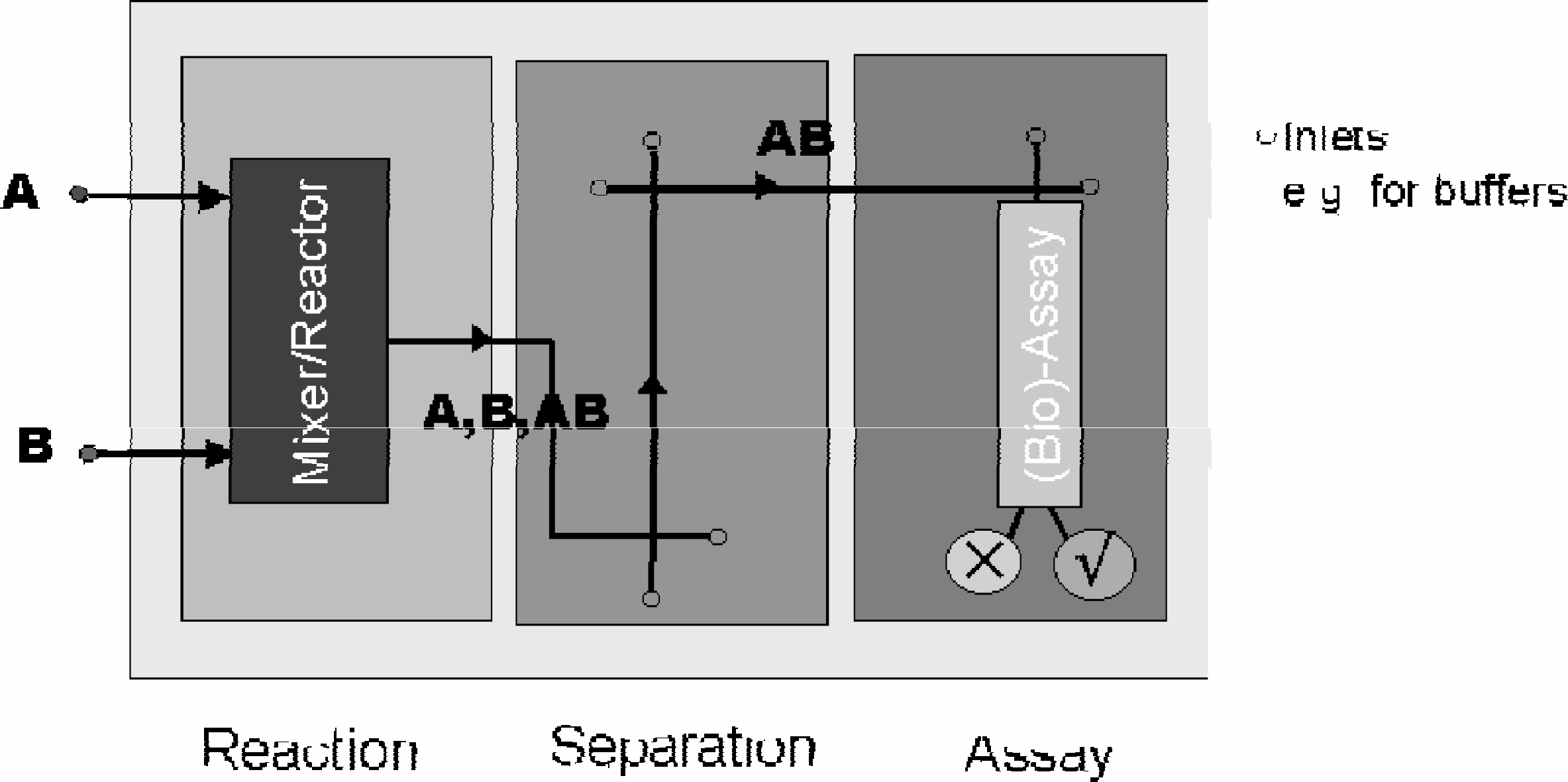
An extension of the μ-TAS concept is that of the micro-synthesis-total analytical systems (μ-SYNTAS). The concept is that of a system where synthesis of chemical compounds and assay (as well as the intermediary steps) will occur on a microfluidic system. In such a way, a ‘chemical microprocessor’ device can be produced — synthesis, isolation and assay of chemicals would be undertaken on a single chip. In a combinatorial system, this would allow for rapid and cheaper identification of active molecules for drug companies. This concept is outlined in Figure 1.

Schematic of a simple μ-SYNTAS chemical reaction microprocessor. Reaction, isolation of products and assay to determine, for example, whether the product is biologically active could all occur on the same device. More complicated devices with a number of reaction, separation and assay steps could readily be envisaged.
APPLICATIONS
This section provides a brief review of a few of the applications of microfluidic devices for chemical reactions and separations and also detection techniques for microfluidic systems. More thorough descriptions of these devices can be found in the referenced literature. There are also a number of recent reviews that give a broader range of applications of microfluidic and other micro-chemical systems than is afforded in this mini-review [5–10].
THE POLYMERASE CHAIN REACTION, PCR
PCR allows for rapid amplification of a number of copies of a specific region of a DNA chain. Since its inception in 1986 [11], it has revolutionized genomics, allowing researchers to produce practical amounts of DNA from minute initial quantities. The reaction has been described in detail elsewhere [12], we shall therefore only provide a brief overview.
The PCR reaction mixture will contain, amongst other chemicals, free dinucleotide triphosphates (i.e., G, A, T and C), the primers (specific DNA chains that determine the zone of the DNA to be amplified), and a thermostable polymerase (typically TAQ-polymerase) — an enzyme that will enable the attachment of the free dinucleotide triphosphates to the DNA chains. The original DNA is first denatured it is melted at 95°C, such that the complementary strands separate. The temperature is then reduced to 55°C, at which point the primers attach to the singlet chains. The temperature is then raised to 72°C, the temperature at which the polymerase is most active. This enables extension of the complementary DNA chains, thus resulting in a duplex, which can then be denatured as the temperature is raised to 95°C again. By cycling the temperature — 95°-55°-72°C-a 2n amplification of the DNA zone defined by the primers can be obtained, where n is the number of cycles undertaken.
Miniaturization gives rise to faster heat transfer and so allows for faster cycling steps in PCR. A number of reported devices have utilized this [13–15] and, for example, Applied Biosystems provide micro-well systems for PCR. Micro-heaters have been incorporated into reservoirs of micro-fluidic chips thereby allowing PCR followed by on chip electrophoresis [16]. In other examples, complete micro-fluidic chips have undergone a number of heating a cooling steps to enable a PCR reaction to occur in a reservoir [17–20].
A true microfluidic PCR system developed by Kopp et al. [21,22] is illustrated in Figure 2. It is a continuous flow PCR chip. Material is passed over three distinct temperature zones, corresponding to the melting, annealing and extending of the DNA. The chip is designed such that the sample passes over these temperature regions 20 times, thus giving a theoretical amplification of 2 20 . Practically, this chip can provide a yield similar to that of a commercial thermo-cycler but with an increased cycling speed of between 12 and 60 seconds per cycle. The design of the chip allows for the PCR to occur continuously, with a continual supply of products being produced (rather than the batches obtained from commercial cyclers). It also allows for up to four plugs of different reactions to be passing through the chip at any one time without any cross-talk occurring between the plugs. This chip can be seen as a chemical amplifier — DNA material entering the chip is amplified in passing through it.
Schematic of the continuous-flow PCR on chip system described in the text. The device is roughly 3cm × 4cm in total size. The sample is pumped through a single channel etched into a glass chip. Three well-defined zones are maintained at 95°, 77° and 60°C by means of themostatted copper blocks. The melting, annealing and extension steps are defined by the channel passing through the three temperature zones. The actual device takes the material through twenty cycles in temperature.
MICROFLUIDIC MIXING DEVICES
Flow in microfluidic systems tends to be laminar. This means that mixing of material occurs solely through diffusional mass transport, rather than through turbulent mixing, as occurs in macro-scale mixing vessels. Diffusional transport is proportional to the square of the diffusion distance, thus reducing the mixing distance required considerably. For example, for a water and an aqueous glycine solution to reach 90% completion of mixing it would take 28 hours if the diffusion distance was 1 cm, 17 minutes over a distance of 1 mm, 0.1 s over 10 microns and 10−5s over a distance of 100nm. It can therefore be concluded that, in the laminar flow regime the simplest way to produce rapid mixing is through splitting the flow to produce a smaller diffusion distance and then to recombine, as illustrated schematically in Figure 3. A number of micro-mixing devices have been reported in the literature [23–25]. It has been stated that such devices can be employed to enable faster and more efficient reactions than traditional mixing vessels [25]. The increased efficiency comes not only from the ability to use some mixers continually (rather than batches with many mixing vessels), but also from an increased yield arising from the fact that the laminar flow does not lead to the ‘hot’ and ‘cold’ spots seen in turbulent mixers, that can adversely effect the reaction. Bessoth et al., have developed a continuous flow micro-mixer (or chemical reactor), capable of on—chip labeling of biomolecules and applications in combinatorial synthesis [26–28].
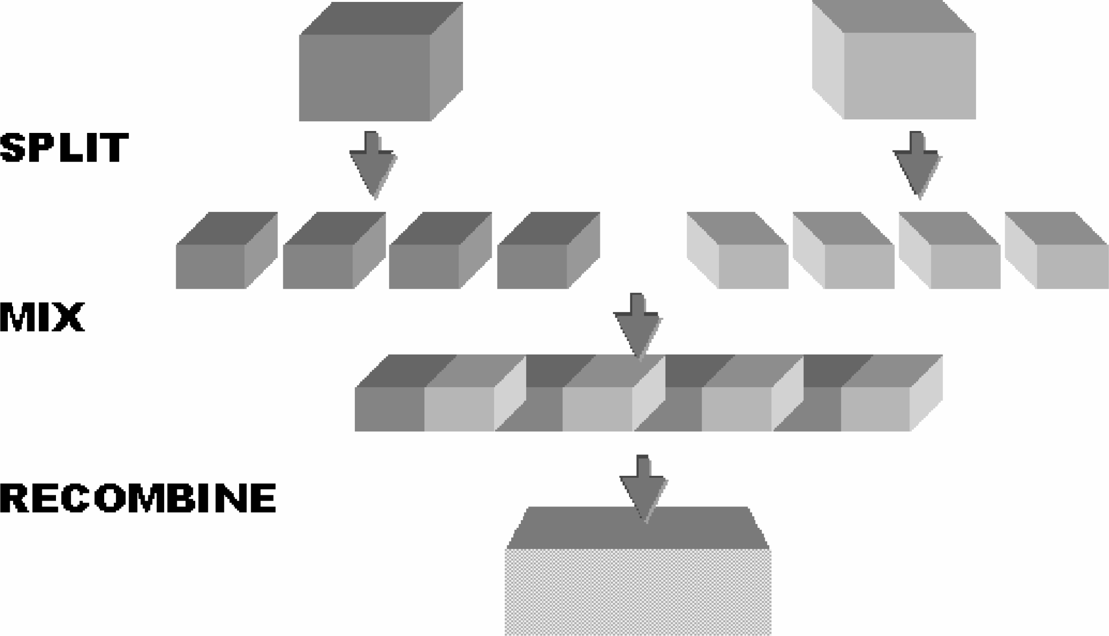
Schematic illustrating how to improve mixing times in a laminar flow regime. By splitting the flow into smaller channels, as illustrated, a decrease in the theoretical mixing time from d2/2D to d2/n22D is obtained (d is the initial channel width, n is the number of channels the flow is split to and D, the diffusion coefficient of the material mixing).
It is possible to see micro-mixers as a step towards μ-SYNTAS devices, with a series of mixers and separators providing a reaction sequence and labeling before a final bioassay.
SEPARATIONS
A number of separation techniques have been incorporated onto microfluidic chips. Indeed the first reported micro-analytical device was a gas chromatograph reported by Terry in 1979 [29]. Since then, electrophoresis [30], electro-chromatography [31], isotachophoresis [32] and isoelectric focusing [33,34], amongst others, have been developed on chip. In all of these devices, an increase in the speed of separation is seen with little or no loss in the resolution of the separation.
The most common application has been in electophoretic devices. In such systems, the reduced joule heating allows for higher fields to be employed in the separation, and electro-kinetic injections can also be employed. Perhaps the most extreme example of the speed of this technique has been the work of Ramsey et al., who have separated rhodamine B and dichlorofluorescein in less than 1ms over 200μm with field strengths of 57kV/cm [35].
Electrophoretic microfluidic devices are now finding a multitude of applications. For example, a large number of microfluidic separation devices have been reported in the field of biotechnology. A 96 channel microfabricated system for DNA sequencing has been developed [36], and devices capable of sequencing short tandem repeats (STRs) in 30s (compared to 2–3 hours in a gel), have been reported [37]. A number of immunoassay systems based upon microfluidics and giving rapid analysis times have been described [38–41]. Both isoelectric focusing (IEF), [34], and sodium dodecyl sulphate electrophoresis (SDS) of proteins [42] have been performed on chips with a massive decrease in the time required when compared to traditional macro-systems (of the order of seconds to minutes compared to hours in gel).
A number of commercial concerns are now developing microfluidic analysis systems based on electrophoretic separations. The last year has seen the release of the Aligent Bioanalyser, the first commercially available microfluidic analysis instrument. This system employs the LabChip technology developed by Caliper Technologies to perform electrophoretic separations for sizing of DNA, RNA and proteins in glass microfluidic devices. Shimadzu have recently presented a microfluidic instrument with quartz chips and U.V. detection (at HPLC 2000 and at PITCON 2000).
DETECTIONS
One of the biggest challenges for research and development in the field of microfluidic devices is that of detection. There are two aspects to this problem; One of increasing the signal to noise (S/N), as a result of the smaller detection volumes associated with microfluidic systems, and the other of actually producing analytical detection devices of a similar scale to the microfluidic devices themselves. In this section we will provide an example of a solution to each of these problems.
SHAH CONVOLUTION FOURIER TRANSFORM (SCOFT) DETECTION [43,44]
The SCOFT detection technique is a method of increasing the S/N in fluorescence-based electrophoretic analyses. The fundamentals of the SCOFT technique are outlined in Figure 4. Typically, detection of analytes in electrophoresis has been performed by single point detections, for example by absorption, fluorescence, conductance or electrochemical techniques. SCOFT extends the detection region from a single point to a zone in a microfluidic channel. Slits cover this detection region, which is illuminated by collimated laser illumination. This provides a detection function — a plug of fluorescent material passing through the region will provide a number of detection peaks. Fourier transform (FT) of the signal will convert the signal recorded as a function of time to a frequency. Different analytes have different electophoretic mobilities and will thus provide different frequencies in the corresponding FT plot.
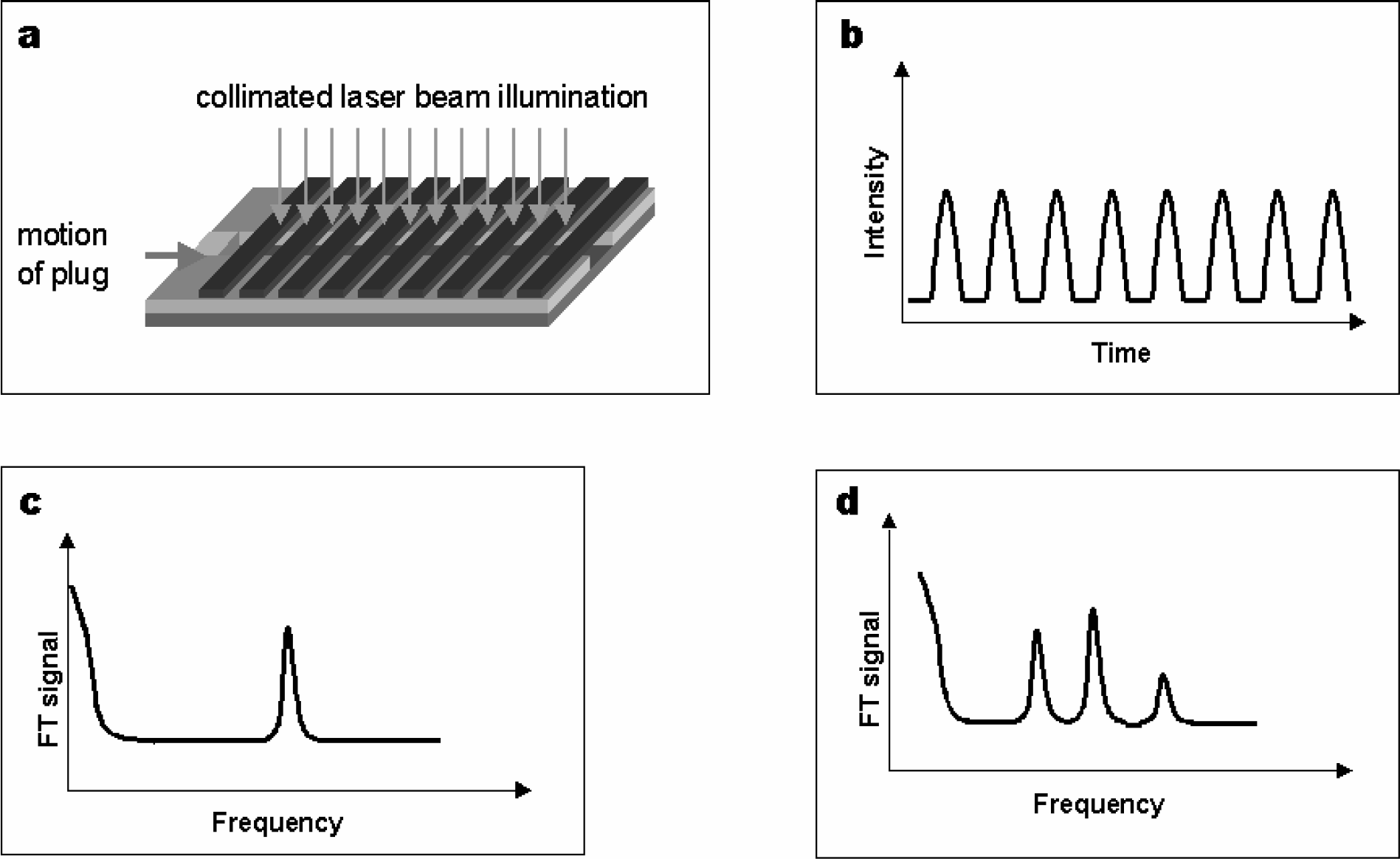
The fundamentals of Shah Convolution Fourier Transform Detection (SCOFT) in microfluidic systems. (
The nature of the FT also removes drift from the final plot, thus eliminating a number of the problems of photo-bleaching and sample leakage that can arise in microfluidic detection systems. The SCOFT technique has been successfully applied, in a chip containing 20 slits, to separate a number of fluorescent analytes. A signal-to-noise improvement of forty times, compared to single point detection, was seen. With the requirements of biology and chemistry tending towards lower sample concentration, and those of microfluidics towards smaller sample volumes, technologies such as SCOFT may well prove to be invaluable.
A DC-PLASMA ON A CHIP [45–47]
Plasma is the forth state of matter, all material in the plasma being ionized. In the past plasma based emission spectrometry has been applied to gas chromatography (GC) analysis. Typically D.C. plasmas are produced in sub atmospheric pressures, however the scaling laws of plasma (see reference for more details) are such that higher pressure plasma are obtainable in smaller volumes (or distances between the electrodes). Figure 5 displays a chip that can provide a plasma for helium gas at atmospheric pressure. The gas enters the chip and a plasma is formed between the two electrodes. The plasma chamber is of dimensions 2000 × 450 × 200μm which corresponds to a volume of 180nL.

Schematic of a DC-Plasma chip. The design is roughly 3×4cm in total size, fabricated in glass with platinum electrodes. 1. Gas inlet; 2. Gas outlet; 3. Pressure sensor connection; 4. Electrodes; 5. Plasma chamber; 6. Electrode connection pads.
This chip has been interfaced to a commercial GC with the spectra of the corresponding plasma taken by a commercially available mini-spectrometer interfaced to the chip via a fiber optic. A mixture of organic material was passed through the GC and the outlet gas was mixed with helium and flowed into the chip. In the plasma, organic material is ionized and dissociated. By measuring the peak of the CH3 vibration it was possible to monitor the comparative concentrations of the organics and their elution time. The plasma chip gave comparable results to the flame ionization detector that was originally connected to the commercial GC.
The plasma chip described can provide detection limits down to the 400ppb range and work at atmospheric pressure with a small detector variance. The system could be envisaged as a portable detector as the gas throughput is 150 mL a week and the power consumed only 9mW.
CONCLUSIONS
Commercialization of microfluidic devices is already progressing at a rapid rate. It is likely that the next few years will see such devices playing an increasingly important part in chemical instrumentation. It is also probable that more integrated devices, providing a number of chemical steps on a single chip, will appear in greater numbers.
The last years have seen the emergence of microfluidic chips in greater numbers and in a wide variety of applications. The future will probably see this trend continuing and microfluidic systems will become an integral part of chemical instrumentation, providing a cheap, rapid and efficient method of lab automation.
If you are interested in seeing more articles like this in JALA, please email