
Abstract
“Mapping the ‘forbidden zone’ near and away from the fixation point”
by Ashley Chung-Fat-Yim, Hiroshi Ono
In the results and discussion section of experiment 1, table 1 reported the standard deviation associated with the arithmetic mean and not the standard deviation associated with the geometric mean. Table 1 below includes the correct geometric standard deviation of each condition.
The critical disparity gradient calculated from the geometric mean of the disparity
gradient (GMDG) values and variability (SD) of the geometric mean. The critical
disparity gradient calculated from the geometric mean of the two slopes (GMTS) of
the lines of best fit and the goodness of fit (R2). Note. Combined disparity gradient values from stimulus situations where the
inducer pin was located 10° to the left and 10° to the right of the median
plane. No variability among ratios is indicated by the standard deviation of unity.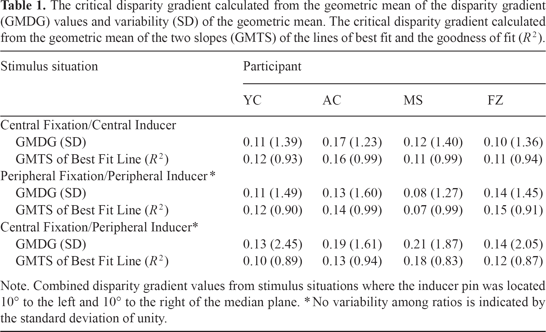
Stimulus situation
Participant
YC
AC
MS
FZ
Central Fixation/Central Inducer
GMDG (SD)
0.11 (1.39)
0.17 (1.23)
0.12 (1.40)
0.10 (1.36)
GMTS of Best Fit Line (R2)
0.12 (0.93)
0.16 (0.99)
0.11 (0.99)
0.11 (0.94)
Peripheral Fixation/Peripheral Inducer*
GMDG (SD)
0.11 (1.49)
0.13 (1.60)
0.08 (1.27)
0.14 (1.45)
GMTS of Best Fit Line (R2)
0.12 (0.90)
0.14 (0.99)
0.07 (0.99)
0.15 (0.91)
Central Fixation/Peripheral Inducer*
GMDG (SD)
0.13 (2.45)
0.19 (1.61)
0.21 (1.87)
0.14 (2.05)
GMTS of Best Fit Line (R2)
0.10 (0.89)
0.13 (0.94)
0.18 (0.83)
0.12 (0.87)
Get full access to this article
View all access options for this article.