
Abstract
Abstract
Bone regeneration is naturally based on bone forming cells, osteoinduction by diverse growth factors, and osteoconduction. The latter one used as term in this study is the ingrowth of bone in 3D structures, which leads to an optimal case in creeping substitution of the scaffold by newly formed bone. Autologous bone is still the gold standard for bone substitutes. In most cases, newly developed bone substitutes consist of calcium phosphate, since hydroxyapatite is the main component of bone and mimics cancellous bone in microstructure. In this study, we wanted to elucidate the optimal microarchitecture for osteoconduction and determine compression strength and Young's Modulus of the selected architectures. Selective laser melting of titanium was used as tool to generate diverse architectures in a repetitive and precise way. To link 3D scaffold architecture to biological readouts, bone ingrowth, bone to implant contact, and defect bridging of noncritical-sized defects in the calvarial bone of rabbits were determined. In this series, 5 different microarchitectures were tested with pore sizes ranging from 700 to 1300 μm and constrictions between 290 and 700 μm. To our surprise, all microstructures showed the same biological response of excellent osteoconduction. However, the mechanical yield strength of these structures differed by the factor of three and reached up to three times the strength of cancellous bone at a porosity of 72.3–88.4%. These results suggest that the microarchitecture of bone substitutes can be optimized toward mechanical strength in a wide range of constrictions and pore sizes without having a negative influence on osteoconduction.
Introduction
From the biological point of view, bone regeneration and healing of bony defects are facilitated by osteoconduction, osteoinduction, and the transplantation of bone cells. The latter one is normally realized by transplantation of autografts, where bone from a healthy site is transplanted to the diseased site 1 or in rare occasions by the use of bone marrow stem cells harvested from the iliac crest.2,3 Osteoinduction as the potential to induce bone formation even at ectopic sites by cell recruitment and differentiation into preosteoblasts was discovered in the 1960s 4 and applied as bone morphogenetic protein-2 clinically from 2002 mainly for spinal fusion procedures. 5 Osteoconduction describes bone regeneration by the potential of bone to grow onto an implant or into porous 3D structures and ideally leads to creeping substitution of the 3D structure by bone as already described in the late 1800s by Arthur Barth. 6 More recently the term “osteoconduction” was also used to describe bone growth on surfaces. 7 Here we mainly refer to osteoconduction as bone growth into 3D structures.
The realization of a patient-specific bone substitute comprises its macroarchitecture as defined as the overall outer shape of the device, its inner microarchitecture reflecting the tissue morphology (e.g., pore size, shape, porosity, spatial distribution, channels, and pore interconnection), and its nanoarchitecture on the surface. The nanoarchitecture is either determined by the production methodology, for example, the grain size of the raw materials or the surface roughness of the fabricated scaffold, or by surface modifications applied after the initial production procedure (e.g., etching, sand blasting, spark anodization, sintering, or even biomolecule attachment for cell adhesion, proliferation, and differentiation).8,9
Additive manufacturing enables the realization of the macroarchitecture of the scaffold and allows the bone substitutes to perfectly fill a patient's bony defect. Maybe even more importantly, additive manufacturing facilitates the realization of a predefined microarchitecture throughout the scaffold needed for an optimal in vivo response in terms of enhanced bone regeneration by osteoconduction. Using powder metallurgy or chemical vapor deposition coating of vitreous carbon scaffolds,10,11 porous titanium scaffolds could only be produced with a homogeneous pore size distribution. Open porous titanium foams produced by metal injection molding with NaCl as placeholders result in a random distribution of the pores. 12 Since all these methods fall short to predefine the exact microarchitecture in terms of location and size of micrometer-sized channels, pores, gradients, or patterns, we have chosen additive manufacturing by laser melting to study the relationship between microarchitecture and biological outcome, here defined as osteoconduction. Despite the limitations of former scaffolds with microarchitectures based on randomly distributed and therefore unsystematic and unplanned pores, those results indicate that pores with diameters between 150 and 500 μm are best suited for bone substitute materials. 13 More recently, pores of up to 1220 μm showed also good results. 14 Data on defined constrictions in scaffold microarchitecture and comparisons of a wide range of pore sizes for scaffolds made from one type of material are still elusive.
Recently, we determined osteoconduction as bone growth into 3D structures of titanium-based implants manufactured by additive manufacturing with defined macro- and microarchitecture but diverse in nanoarchitecture to fit a 6 mm noncritical-sized defect in the calvarial bone of rabbits. From all the implants produced by selective laser melting (SLM), we found the sand-blasted acid etched implants to be superior to native SLM and sand-blasted SLM ones. 15 In this study here, we used the same model and tested native SLM implants of defined macro- and nanoarchitecture but different in microarchitecture types A–E for impact on osteoconduction and mechanical performance. The results showed that an optimization in mechanical functioning in the evaluated range of diverse microarchitectures could be achieved without compromising osteoconduction of the implants.
Materials and Methods
Implant design
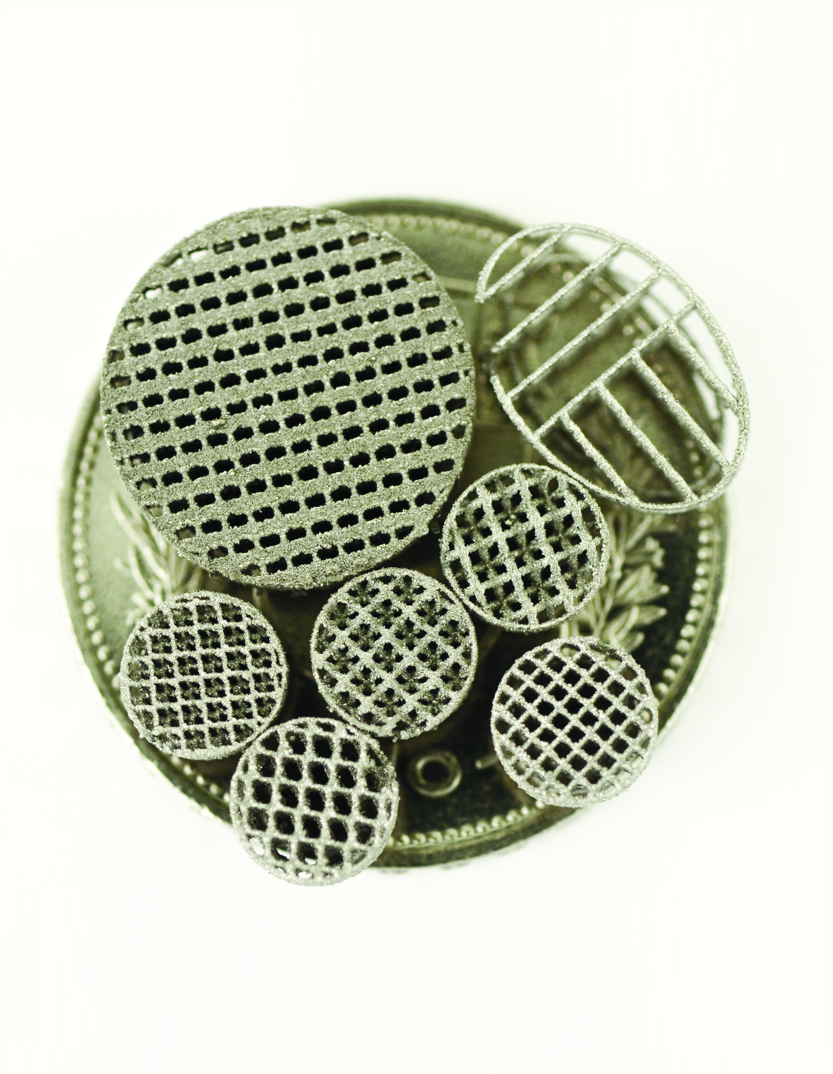
The titanium-based scaffolds used in this study were designed with the Software Solidworks V.2013 (www.solidworks.com, Dassault Systèmes, France) and Magics V.15 (www.materialise.com, Materialize NV, Leeuven, Belgium), based on unit cells as illustrated for the diverse building blocks (Fig. 1a and Table 1). All macroarchitectures consist of a stepped cylindrical shape with a total macroscopic height of 3.8 mm (Fig. 1b, c). The diameter of the larger macroscopic cylinder was 7.5 mm, while the smaller outer diameter was 6 mm. The microarchitectures are based on categorized open porous lattice types A–E.

Micro- and macroarchitecture of the scaffolds:
The microarchitectures of the implants were constructed by replicating the corresponding unit cell types A–E as a space filling pattern in all spatial dimensions inside the staged cylinder (Fig. 1), leading to an overall porosity of 72.3–88.4%. The lattice architecture type A consists of orthogonal struts with thickness 200 μm and periodicity of 900 μm. The open channels (marked by arrow in Fig. 1a) have a dimension of 700 μm. Type B lattice is constructed by 600-μm-thick pores along all three room diagonals of the cubic unit cell with a unit cell length of 1.1 mm. The lattice architecture type C is derived by repeatedly subtracting spheres of diameter ø1.36 mm with a repetition distance of 1.2 mm in all three orthogonal directions, resulting in spherical cavities connected with each other by “bottle necks” of 660 μm diameter. Lattice types D and E are both based on rhombohedral dodecahedron (RDH) symmetry, D with an elementary cell length of 1.41 mm and E with 1.79 mm. The strut size selected was 400 μm for type D and 510 μm for type E leading to final persistent channels with a diameter of 290 μm and resp. 380 μm for scaffold types D and E.
In addition, boundary rings are added around the lattice structure to define the border and to avoid sharp edges. A pin is added, which is necessary during the SLM building procedure, the post-treatment, and the surgical placement of the scaffold during implantation (Fig. 1b). It can easily be disconnected at the predetermined breaking point without destroying the scaffold.
3D characterization
Whereas simple geometrical parameters such as strut thickness and pore size from type A (Table 1) were derived directly from the geometrical definition, more complex 3D considerations were numerically calculated with the “3D analysis-function” of the CTAn software (version 1.8.0.5; SkyScan NV) 16 from the stl-files of scaffold types A–E, excluding the symmetry breaking closing rings and the transfer pin. For all five implant types A–E, a cylindrical volume of interest (VOI) with a diameter of 5.08 mm and a height of 3.56 mm was selected to characterize the microarchitecture inside the scaffold resulting in a total VOI volume of 72.1 mm3.
Implant production
All implants were produced in the SLM Realizer 250HT Selective Laser Melting machine (SLM Solutions GmbH, Lübeck, Germany) operated with a continuous wave Ytterbium fiber laser with a wavelength between 1068 and 1095 nm. Ti-powder (Ti grade II according to Ref. 17 with a d50-value of 60 μm) was used as raw material (SLM Solutions GmbH). The powder layer thickness was set to 30 μm. The fusion of the titanium particles by the laser occurred at an energy density of Ev of 63 J/mm3. In analogy to Ref. 15 , the transfer pins were positioned vertically onto the building platform with the tilted scaffolds at the front end (Fig. 2a). After fabrication and excavation from the surrounding titanium powder, adhering powder particles were first removed by compressed air and then by ultrasonic cleaning in a 4% Deconex® 15PF (Beiersdorf Münchenstein, Switzerland) solution at 90°C for 15 min. Next, the implants were cleaned three times in ultrapure water (resistivity 18.2 MΩcm) for 5 min in an ultrasonic bath with intermittent rinsing under flowing ultrapure water and thereafter were passivated two times in concentrated nitric acid (32.5% HNO3, Fluka 84380) at room temperature under ultrasonic application for 10 min. Finally, an ultrasonic cleaning and rinsing sequence in ultrapure water for 5 min was repeated three times. A final cleaning and sterilization procedure was done using RF plasma treatment with high-purity oxygen (PDC-32G, Harrick, Ithaca, NY; oxygen purity 99.9995%, Carbagas) at 29.7 W for 5 min. No additional surface treatment was applied. After packaging and labeling, the implants were gamma sterilized with 25 kGy.
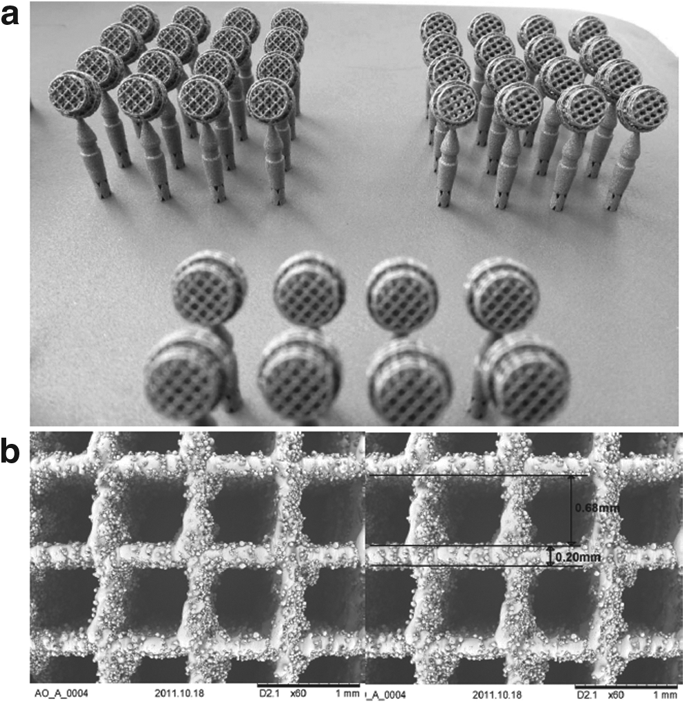
Scaffolds on the selective laser melting (SLM) building platform after excavation and scanning electron microscopy:
Surgical procedure
Eleven adult (12 months old) New Zealand White rabbits, weighing between 3.5 and 4.5 kg, were used in the present study. The animals were housed in groups in a purpose-designed room for experimental animals and fed a standard laboratory diet. The methodology of animal trial was evaluated and accepted by the local authorities (108/2012). Animals were anesthetized by an injection of 65 mg/kg ketamine and 4 mg/kg xylazine and further anesthetized with isoflurane/O2. The surgical area was disinfected and an incision was made from the nasal bone to the mid-sagittal crest. Next, the soft tissues were reflected and the periosteum was elevated from the site. In the area of the right and left parietal and frontal bones, four evenly distributed 6-mm-diameter craniotomy defects were prepared with a trephine bur under copious irrigation with sterile saline. For the completion of the defect, a rose burr (1 mm) was used to preserve the dura. Before implant placement, bone debris were removed by flushing with saline. Each of the animals received four different treatment modalities. In the first round, empty and design A implants were applied with two other implants, which are not included in this report. In the second round, all animals received implants of the designs B, C, D, and E. The treatment modalities were assigned at random for the first animal, and thereafter, cyclic permuted clockwise for the next three animals. For the fifth animal, treatment modalities were again assigned at random. After carefully placing the implants into the defects and detachment of the transfer pin, the soft tissues were closed with interrupted sutures. After a healing period of 8 weeks, the rabbits were placed under general anesthesia and sacrificed by an overdose of pentobarbital. The skull containing all four craniotomy sites was removed and placed in 40% ethanol.
Embedding
The specimens were prepared with a sequential water substitution process. It involved 48 h in 40% ethanol, 72 h in 70% ethanol (changed every 24 h), 72 h in 96% ethanol, and finally, 72 h in 100% ethanol. Thereafter, samples were placed in xylene for 72 h (changed every 24 h) followed by methyl methacrylate (MMA) for 72 h (Fluka 64200) and 100 mL MMA +2 g dibenzoylperoxid (Fluka 38581) at 4°C for 4 days. For polymerization, samples were submerged in 100 mL MMA +3 g dibenzoylperoxid +10 mL plastoid N or dibutylphthalate (Merck 800 19.25) at 37°C in an incubator. After embedding, the skull was cut in four pieces each containing one craniotomy site by using an EXAKT 300P saw (Exakt, Norderstedt, Germany).
Histomorphometry
Histomorphometric analyses were performed from the middle sections using image analysis software (Image-Pro Plus™; Media Cybernetic, Silver Springs, MD). The area of interest (AOI) was defined by the implant dimension. New bone formation in the AOI (new bone area, mm2), bone to implant contact (BIC, %), and percent of bone in the AOI of the areas devoid of titanium (bone filling, %) were determined. For the latter, empty control value of the average area occupied by titanium of all five designs was taken into account and subtracted from the AOI.
Bone bridging
Bone bridging was determined in the middle section. First, the areas with bone tissue were projected onto the x-axis. Next, the stretches of the x-axis where bone formation had occurred at any level were summed up as described earlier.18,19 Bone bridging is given in percentage of the defect width (6 mm) where bone formation has occurred.
Evaluation of the mechanical properties of the implant material
A universal material testing machine (Z100 THW all-round-line, 100 kN X-force load cell; Zwick GmbH & Co. KG, Ulm, Germany) under uniaxial compressive load was used to analyze the mechanical properties of the porous scaffolds types A–E as well as solid SLM material. In agreement with the intra- and postoperative biomechanical loading, the implants were positioned between two hard metal compression inserts in a horizontal position. The samples were first preloaded with 2 MPa. Then, a constant strain of 0.001 s−1 was applied at room temperature, while the resulting force and deformation were recorded during the strain-controlled compression phase.
Surface analysis
To characterize the morphology of the nano- and microarchitecture, the implants and their surfaces were inspected by SEM (TM-1000, Hitachi, backscattered electrons, acceleration voltage 15 kV, energy dispersive X-ray spectrometer EDX, SwiftED-TM detector). The surface roughness was quantified by a confocal laser scanning microscope (LEXT, Olympus OLS 3100 with a 50 × objective) using a cutoff wavelength of λ = 1/10 = 10 μm.
Statistical analysis
The primary analysis unit was the animal. For all parameters tested, the 6 treatment modalities were compared with a Kruskal–Wallis test, followed by pairwise comparison of treatment modalities with the Mann–Whitney test for dependent data (IBM SPSS v.19). p-Values are displayed in the graphs and significance was set at p < 0.05. Data from 11 rabbits are presented. Values are reported as mean ± SD and displayed as box plots ranging from the 25th (lower quartile) to the 75th (upper quartile) percentile, including the median and whiskers showing the minimum and maximum.
Results
Implant production
The implants, including the transfer pins with the predetermined breaking point, were produced on the SLM building platform (Fig. 2a), whereas the bicylindrical macroarchitecture is identical for all scaffold types A–E, the five different microarchitectures are produced according to the designs described in Figure 1. The nanoarchitecture of the native SLM surface is shown in SEM images (Fig. 2b). The struts of, for example, scaffold type A have a thickness of ∼200 μm and are decorated by residual titanium particles from the initial powder. The roughness, measured on the struts by confocal laser scanning microscopy, is Ra = 3.24 ± 1.05 μm, SRa = 3.37 ± 0.27 μm, and SRz = 46.88 ± 4.23 μm. Due to this particular coverage, the actual surface is increased by an enlarging factor α = 2.64 compared to the projected area.
3D characterization
Basic geometrical parameters such as strut thickness, maximal constrictions, porosity, degree of anisotropy, object volume, object-specific surface, connectivity, and pore size are listed (Table 1). The porosity of the microarchitecture varies between 72.3% and 88.4%. The diameter of the minimal constrictions lies between 0.29 and 0.7 mm, showing that lattice type D features the tightest “bottle necks,” whereas all inner pores of lattice type A can be reached easily through a neck of 0.7 mm diameter.
Type A shows the most discrete structure thickness distribution since all struts have the same diameter throughout the scaffold (Fig. 3a). In the more complex designs such as in type B, C, D, and E with polygons, spheres, and radii, the thickness distribution shows broader and asymmetric peaks with shoulders.
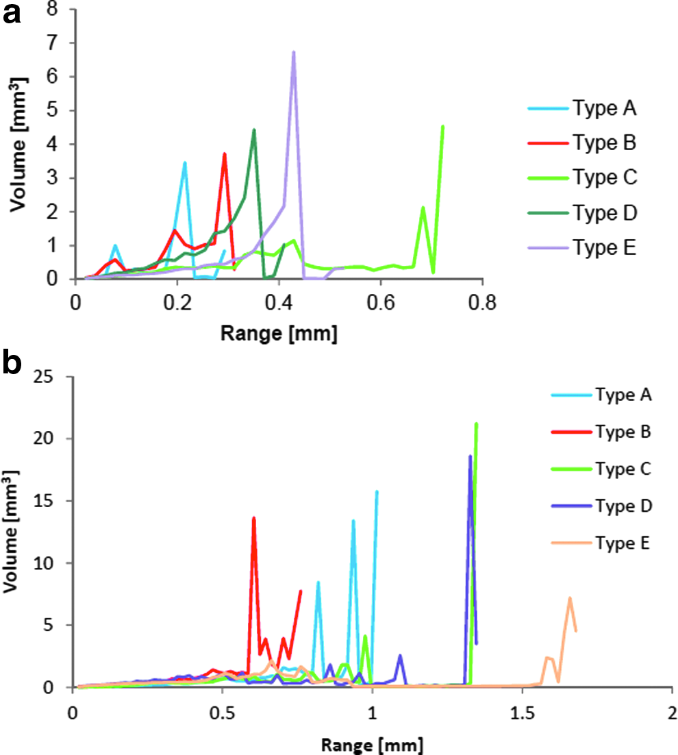
Structure thickness distribution
The struts in type A microarchitecture have a thickness of 200 μm and are separated by 0.7 mm, characterized by the peak in the structure thickness distribution at 0.2 mm (Fig. 3a) and ∼0.8 mm in the structure separation distribution (Fig. 3b). The diagonal length of the elementary cell in type A is 0.99 mm, which explains the second peak at 0.95 mm in the structure separation distribution (Fig. 3b). In type B lattices, the pillars between the channels have a diameter of 0.26 mm, which is reflected in the first peak of the structure thickness distribution. The structure separation distribution of type B microarchitecture shows a peak at ∼0.6 mm (Fig. 3b), which corresponds to the channel diameter of 0.6 mm. In cross points of the channels, the struts are separate by 0.73 mm leading to a second peak. The diameter of the empty sphere inside the elementary cell of type C is 1.36 mm and therefore explains the peak at 1.35 mm in the structure separation distribution (Fig. 3b), while the concave curvature leads to a broadened structure thickness distribution up to 0.45 mm (Fig. 3a). The peak at 0.7 mm corresponds to the massive corners remaining between the spheres with a thickness of 0.72 mm. Both microarchitectures D and E are based on RDH cells, however, designed with different scales. Due to thicker struts in microarchitecture E compared with D, the asymmetric peak of the structure thickness distribution is shifted toward higher values (Fig. 3a). However, the aimed strut thickness of 0.4 mm, resp. 0.5 mm are not well mapped, tails toward lower thicknesses appear due to the imprecise strut thickness in the digital stl-model (Table 1). The expected diameters of the RDH cavities are ca. 1.3 mm (type D) and ca. 1.6 mm (type E). The peaks in the structure separation distribution in type D are also shifted from 1.33 to 1.66 mm in lattice type E due to the upscaled elementary RDH cell (Fig. 3b).
In general, a smaller object volume correlates to a larger porosity of the same object (Table 1). Results for the object-specific surface indicate that type A and B are the most complex/filigree microarchitectures, while type C is the least complex, that is, the most clumsy structure. This goes along with the results for connectivity, which states that microarchitectures type A and B are topologically more intensively connected than the other microarchitectures (i.e., more cuts are necessary for a geometrical separation). Furthermore, the degree of anisotropy of the microarchitectures type A and B is significantly larger compared to type C, D, and E. This increased anisotropy reflects the enhanced preferential structural alignment along particular spatial axis of architectures A and B.
Mechanical characterization
The values for the components Young's Modulus E (with reference area of the small ø6mm cylinder cross section), the Yield Strength R0.2, and the maximum strength before structural failure Rm are listed (Table 2).
SLM, selective laser melting.
Bone formation
All treated animals showed an uneventful healing and stayed in good health. In the ground sections, no signs of inflammation could be detected. Bone formation occurred close to and in contact with the bone substitutes irrespective of the designs used (Fig. 4), which indicates a good biocompatibility over the first 8 weeks on implantation for all SLM implant designs.

Histological sections from the middle of the defect and illustrations of the implant designs A–E. For all scaffold designs from A to E and an empty defect, a histological section from one exemplary animal 8 weeks postoperatively is shown. Scale bars indicate 1 mm. Original magnifications were 100-fold. Bone appears as grayish purple to purple. The size of the original defect is indicated in the histological section B.
The histomorphometric analysis (Fig. 5a) of the middle sections revealed that the area of newly formed bone of the designs B, C, and D was significantly higher (p = 0.08) than in the control group where no implant was placed. Between the groups with implants, the area of newly formed bone was not significantly different. The bone filling show a similar trend like the bone area (Fig. 5b). Over the first 8 weeks after implant placement, defect bridging in defects treated with implants was almost complete (Fig. 5c). The BIC was in a very close range for all implant designs and not significantly different (Fig. 5d).

Bone histomorphometric parameters in the area of interest (AOI).
Discussion
Osteoconduction is a strong driving force in bone healing and particularly important when bone substitute materials are applied. In this study, we evaluated metallic bone substitutes with diverse microarchitectures. Such defined microarchitectures can be realized by the application of additive manufacturing; in this case, SLM of titanium powder. The results showed that the different microarchitectures with varying topological complexity had a substantial input on the mechanical properties but no input on the biological readout such as bone formation and bony bridging of the defects.
Histologically, there is no significant difference in bone ingrowth between the various microarchitectures. Despite the 5 open porous microarchitectures based on completely different architecture with different symmetries, accessibilities, connectivity, and anisotropies, their porosity p is in a narrow range 72.3% < p < 88.4% and very close to cancellous bone. 20 Obviously, a minimal constriction of 290 μm (type D) is enough for vascularization and tissue ingrowth, which is in agreement with 13 stating that 150–500 μm pores are optimal for porous biomaterial. In terms of minimal constriction, bone formation also occurs in pores of 50 μm and below, 21 but vascularization in such pores appears to be the limiting factor, since it was shown that bone formation in pores of 90–120 μm induces osteochondral ossification, whereas those with larger diameters (350 μm) induced bone formation directly within the tunnels. 22 The maximal optimal pore size for Haversian-type bone formation was suggested to be 300–400 μm. 22 A majority of articles on optimal maximal pore size suggest the largest evaluated pore size as optimal, which was in the range of 350–400 μm.23,24 In 2 articles, pores of 400–600 μm performed worse than the ones between 350 and 400 μm since pores in the range of 400–600 μm, occupied by adipocytes and bone marrow, lead to the formation of multiple capillaries 25 and translated to a reduction of the mechanical properties. 22 In a more recent study, 14 cylindrical scaffolds of ß-TCP were implanted in cancellous bone of sheep, but no difference in bone ingrowth was seen between pores in the range between 150 and 1220 μm, which is in line with our results. Due to the random distribution of these pores, the size of the constrictions, however, could not be determined.
In our scaffolds, constriction varied between 290 μm (microarchitecture D) and 700 μm (microarchitecture A) and pore size from 700 μm (structure A) to 1300 μm (microarchitecture C) and are thus more diverse and more defined than that of aforementioned scaffolds. Especially for larger scaffolds, the interconnection pathway could limit the accessibility and the vascularization. 26 With the wide open porous structures from our studies, vascularization even with larger scaffolds should not be limiting, since the minimal constraint is 290 μm, which still allows Haversian-type bone formation that includes blood supply. 22
An increase in surface between 1% and 42% had no effect on the biological readout. Since the surface roughness of all these scaffolds is the same, it suggests that the surface area in the range of the tested scaffolds has no effect on osteoconduction. In a recent study, we showed that moderately rough surfaces as produced by sandblasting and acid etching had a significant effect on osteoconduction. 15 A uniform surface treatment with sandblasting throughout large scaffolds can hardly be achieved or demand special architectures to allow the uniform penetration and impact of sand particles. 27
Titanium scaffolds with concavities of 1600 μm diameter and 800 μm depth implanted in muscles induced bone formation preferentially in the concavities. 28 Our scaffold (type C) resembles concavities of 1300 μm diameter and 650 μm depth, but showed no significant increase in bone formation compared to all other scaffolds, including microarchitectures based on squares (type A). The type A scaffold was also used in a former study to heal critical-sized defects in rabbits and proved to enhance defect bridging substantially to the same extent than in combination with osteoinductive growth factors or hydroxyapatite-based granules. 29 Therefore, one can assume that round-shaped microarchitectures are not superior to rectangular-shaped ones in terms of osteoconduction. For osteoinduction, however, round shapes as in concavities appear to be more effective28,30 may be due to their resemblance to resorption lacunas generated by osteoclasts during bone degradation. 31 Biomimetic osteoinductive surfaces were studied with sintered highly crystalline solid HA discs with hemispherical indentations of 2 mm as defined concavities on one or both planar surfaces.28,32 With microarchitecture C, we realized pores of 1.36 mm in diameter throughout the scaffold but saw no indications for osteoinduction in terms of enhanced bone formation. For future studies, additive manufacturing will facilitate the realization of new designs to evaluate the effect of concavities and osteoinductive 3D designs in greater detail.
Conclusion
In future, additive manufacturing will enable the production of personalized scaffolds to treat patient's large bone defects more successfully. At present, it allows the realization of experimental scaffolds with an unlimited variety of microarchitectures to study the relationship between microarchitecture and enhanced bone regeneration by optimized osteoconduction. In this study, we show that osteoconduction of open porous bone substitutes with constrictions between 290 and 700 μm and pore sizes between 800 and 1300 μm is independent of the microarchitecture. The choice of the microarchitecture, however, has a great impact on the mechanical stability of the scaffold. Further studies are ongoing to elucidate the optimal microarchitecture for osteoconduction. Such an optimum exists since the empty defect with a constriction and pore size of 6000 μm performs significantly worse than any microarchitecture tested in this study.
Footnotes
Acknowledgment
We thank Flora Nicholls, Ana Perez, and Alexander Tchouboukov for excellent technical assistance and Alexander Zwahlen for the 3D analysis of the structures. This research work was supported by a grant from the Swiss National Science Foundation (31003A_140868) and by the AOCMF (project C-10-37W), the Craniomaxillofacial Specialty of the AO Foundation.
Author Contributions
M.d.W.: Study design, surface characterization, main article writing. S.Z.: Design of the scaffolds. J.R.: Mechanical analysis. R.S.: Production of the scaffolds. T.F.: Surgical procedure, histology. C.G.: Surgical procedure, histomorphometry. F.E.W.: Study design, surgical procedure, data analysis, main article writing.
Author Disclosure Statement
No competing financial interests exist.