
Abstract
Abstract
Pressure anemometers suitable for fabrication by 3D printing employing fused deposition modeling (FDM) technology were designed, built, and tested in a wind tunnel, the work being initiated by attempting to create a particular type of this class of instruments, commonly known as a Pitot tube. After initial issues due to the porosity of the parts, a consequence of the FDM technique, and difficulties in clearing the interior of the probes after manufacturing, a suitable design solution was achieved, with the results from the 3D printed probe being finally identical to those of a standard reference metallic Pitot tube at the investigated airspeed range of 2.1–31.5 m/s. Exploiting the freedom of form that 3D printing allows, several special-shaped pressure anemometer geometries were designed, with the intent of increasing the pressure signal outputted from the probes to achieve a better measurement precision, particularly at low air speeds. In the process of shape exploration of the pressure enhancing probes, computational fluid dynamics experiments were performed to give insights on suitable designs. The special-shaped pressure probes were tested at speeds ranging from 2.2 to 10.4 m/s, with the maximum pressure signal amplification being obtained by a 3D printed Pitot tube of basic conventional geometry equipped with 3D printed add-on parts. This result is relevant as it shows that existing Pitot tubes of traditional metallic construction can have their pressure output enhanced with the installation of bespoke fabricated 3D printed add-on parts. Although 3D printing did not prove to be particularly advantageous to fabricate simple Pitot tubes, special-purpose complex-shaped pressure anemometers can strongly benefit from this technology due to the freedom of shape design at no extra cost that it allows.
Introduction
P
Traditional construction methods of a Pitot tube, though not overly complex, imply skilled craftsmanship, precision lathing, drilling, and soldering of its several parts. The idea of investigating 3D printing for fabricating this type of instruments was inspired by the potential simplicity of manufacturing offered by this technology and the freedom to explore and fabricate complex shapes without the added cost it provides.3,4 These key characteristics of 3D printing have already led it to be employed to build instrumentation and equipment for scientific research in fluid dynamics, with recent examples such as liquid flow meters 5 and models for wind tunnel testing.6–8 In this last application, the ability of 3D printing to effortlessly reproduce the complex shapes of aerodynamic parts is a remarkable asset.
It is interesting to remember that numerical control machining, one of the technological milestones that enabled 3D printing to be developed, was driven by the necessity to fabricate aerodynamic-shaped parts with very high accuracy. 9
A Pitot tube consists of a pressure port at the tip, directly facing the flow, stopping it locally, and thus capturing both its kinetic and random molecular energy, this quantity being called the total pressure (pt), and a set of pressure ports downstream, parallel to the flow to avoid disturbing it, designed to capture only its random molecular energy, called the static pressure (ps). According to Bernoulli's principle in fluid mechanics, the energy at both types of ports is the same and thus, as the flow's speed at the tip port is zero, at the static pressure port's location the flow's speed (v) [m/s] can be calculated by employing Equation 1
10
by measuring the total pressure (pt) [Pa] and the static pressure (ps) [Pa], thus obtaining the pressure differential Δp = pt- ps, with
One shortcoming of this type of instruments is their small pressure signal at low speeds, typically problematic below 4 m/s. 11 This fact, and the freedom of design that 3D printing allows, led the authors to explore special-shaped probes to increase the pressure signal at low speeds, a topic detailed later in the article. Although a number of pressure-enhancing anemometers were conceived in the past,11,12 none employed 3D printing, and neither involved the modification of conventional Pitot tubes by the application of bespoke fabricated parts like in the present work.
A general view of all 3D printed parts produced is presented in Figure 1: the first design of a Pitot tube, probe A, the final design, probe B, and objects (C), (D), (E), and (F), which are special-shaped probes and add-on parts, designed to enhance the pressure signal outputted from the probes to increase their sensitivity at low airspeeds. Probe (C) is a modification of probe (B) with an airfoil-shaped cross-section at the static ports' location, whereas part (D) is a completely different design, with a venturi-shaped top section where the static pressure ports are located. Parts (E) and (F) are add-ons to be installed around the static pressure ports of part (B): Parts (E) are two types of venturis, and parts (F) are two types of rings that transform a normal Pitot tube into one with a shape similar to that of part (C).
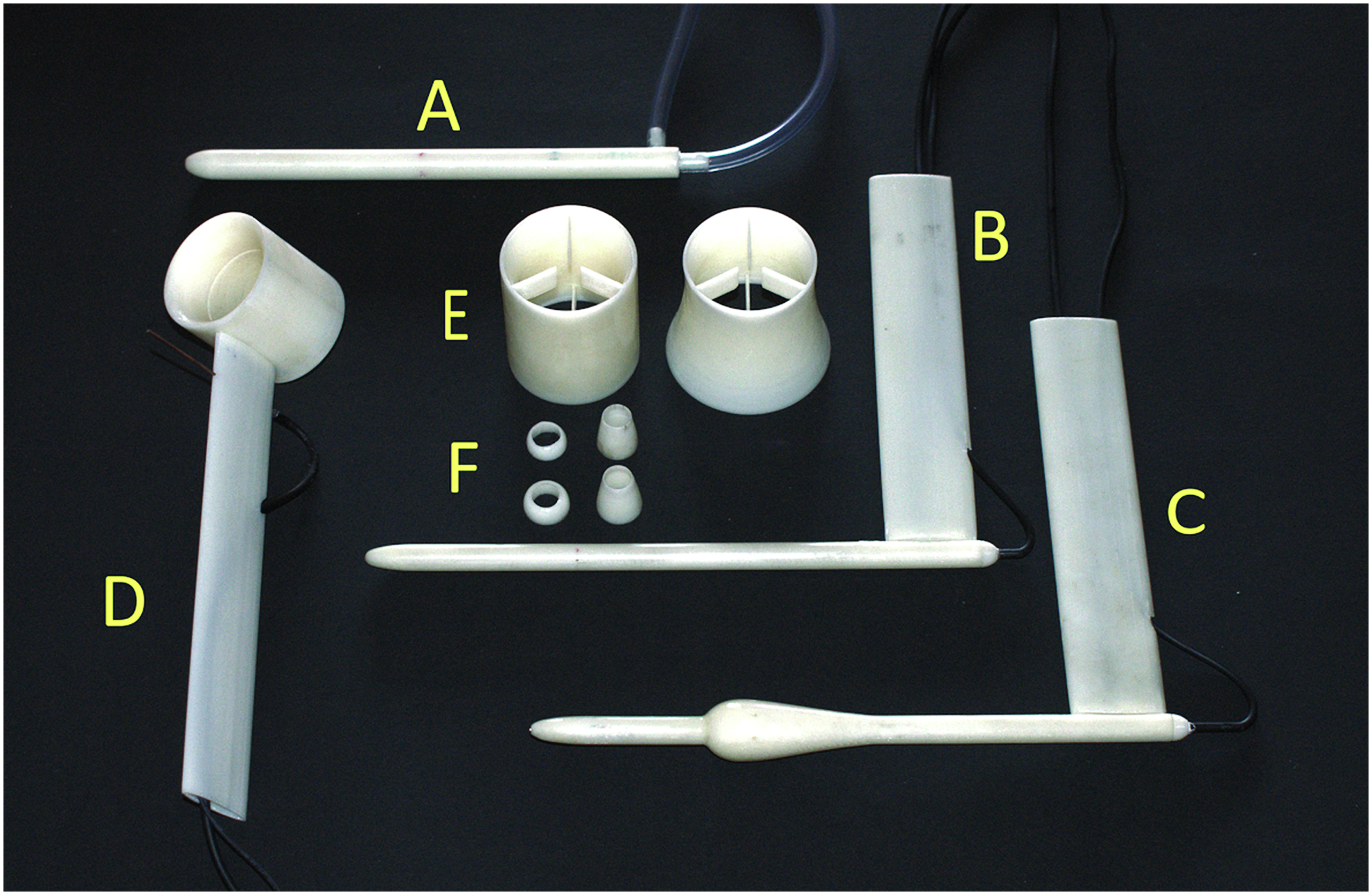
General view of all 3D printed parts. The first design of a Pitot tube, probe
Manufacturing and Wind Tunnel Testing Equipment
Among the several 3D printing technologies available, extrusion-based processes are currently the most popular on the market, 13 and within these, by far the most common is fused deposition modeling (FDM), presently existing in more 3D printing machines using FDM than any other additive manufacturing technique. 13 Due to its widespread use, low cost, and the fact that parts produced by FDM are among the strongest for any polymer-based 3D printing process, 13 FDM was the technology employed in the present work, although a problem that had to be overcome was that FDM does not produce fully dense parts.14,15
Competing 3D printing techniques that also produce polymer-based parts are stereolithography (SLA), selective laser sintering (SLS), material jetting, and binder jetting. Within each technique, part accuracy, surface finish, and strength vary greatly with the quality of the 3D printing machine used, as well as the type of consumables employed. Nevertheless, a short comparison of FDM with the previously mentioned alternative manufacturing processes follows.
Compared with FDM, SLA machines, as well as the consumables, are typically more expensive, with manufactured parts characterized by better accuracy, surface finish and being fully dense. Drawbacks are lower strength, 16 worsening mechanical properties over time, sensitivity to UV radiation, 13 and much lower deflection temperatures than FDM, typically 45°C versus 95°C, facts that preclude SLA parts to be used as functional objects in many applications. SLS and material jetting 3D printers are considerably more expensive than FDM machines, the consumables are also costlier, and the resulting parts globally have surface finish, accuracy, and strength comparable to those produced by FDM.13,17,18
Parts manufactured by binder jetting technology are inherently weaker than those produced by FDM, needing an additional step in the manufacturing process, consisting of the application of an infiltrant, to improve their mechanical properties.13,19 Binder jetting printers are typically more expensive than FDM ones, the consumables being of a comparable price. The accuracy and the surface finish of objects manufactured by binder jet technology are usually inferior to those of FDM-manufactured parts.
The 3D CAD tool employed to draw the parts was the Rhinoceros™ modeling software, and the parts were fabricated in an FDM Stratasys™ uPrint SE machine. The machine had a build size of 203 × 152 × 152 mm, with the parts being fabricated in layers with a thickness of 0.254 mm. To process the STL CAD files and generate the printer building paths, the CatalystEX™ software was employed, with the option to print the parts as solids selected to maximize their density. After printing, the parts were placed in a Stratasys WaveWash machine to remove the supporting structures.
The parts were made in the ABSplus-P430™ thermoplastic from Stratasys, a material that has an advertised maximum tensile strength of 33 MPa and proved rugged enough for the airspeeds experienced during the wind tunnel tests. The heat deflection value of 96°C of the ABSplus-P430 thermoplastic is considered sufficient for most applications of pressure anemometers. If better material properties are needed, Stratasys supplies the ULTEM 1010 Resin™, its strongest, most heat-resistant material, with a maximum tensile strength of 64 MPa and a 216°C heat deflection. Due to the anisotropic nature of the FDM building process, 20 the parts were built so that their larger dimension was aligned with the X horizontal axis of the 3D printer, as parts manufactured by FDM are weakest along the vertical Z axis of construction. 13
The experiments were performed in an open circuit wind tunnel manufactured by Plint & Partners™, model TE44, with a test section of cross-dimensions that were 400 mm × 400 mm and capable of airflow speeds up to 33 m/s. The wind tunnel was powered by an electronically controlled electric motor, allowing an almost continuous variation of the airflow's speed. To avoid blockage effects, the probes were mounted 200 mm downstream of the wind tunnel's exit and at the center of its cross-section. A 3D printed pressure probe ready for a test run is presented in Figure 2.
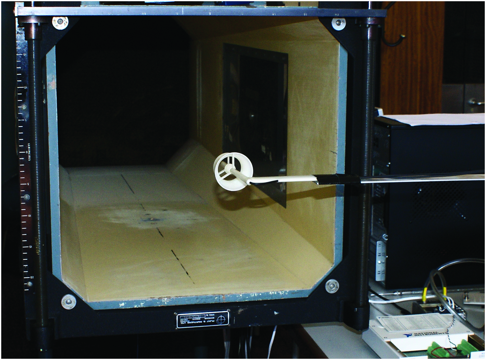
View of the wind tunnel with a 3D printed probe ready for a test run. Color images available online at www.liebertpub.com/3dp
The pressure signal produced by the probes was measured with an Omega™ PX635 precision laboratory transducer that has an accuracy of Δp1 ≈ 0.123 Pa in the range of pressures investigated. The Omega pressure transducer was calibrated with a Betz micro-manometer that has itself an accuracy of Δp2 ≈ 0.490 Pa, which corresponds to half of the instrument's scale resolution, that is, 0.05 mm H20. The standard error of the pressure transducer calibration curve was Δp3 ≈ 0.422 Pa. The global pressure measurement accuracy, given by Equation 2, is
Based in the previous calculations, the estimated uncertainty in airspeed measurement is presented in Table 1.
The transducer's analogue output was converted by a 16-bit National Instruments™ (NI) DAQPad-6015 data acquisition board connected to a PC equipped with NI's LabVIEW software, the setup being globally similar to the one employed in Ref. 21 Each stored pressure reading consisted of an average of 20,000 samples recorded during 1 s.
3D Printed Pitot Tubes
Initial design of a 3D printed Pitot tube
In the first design of a 3D printed Pitot tube, an attempt was made at fabricating the device in one single part and without a sealing coating. As previously mentioned, the authors were aware that problems might arise due to the porosity associated with the FDM technique,14,15 but, nevertheless, the investigation started with this first step to observe the performance of an unsealed single part.
The technical drawings of the first and final designs of the 3D printed Pitot tubes are presented in Figure 3. All technical drawings presented throughout the article were drawn by using a first-angle projection with the dimensions in millimeters. The first design was a compromise between a reasonable outer diameter (10 mm) and the desire to have a relatively large wall thickness (1.7 mm) in both inner and outer pressure channels to minimize the risk of air leakages. The static ports were placed 8 diameters behind the leading edge of the probe to avoid flow disturbances in the tip region of the probe. 22 In this exploratory first design, no special provision was made to support the probe, which was simply taped to a long metallic arm to expose it to the airflow.
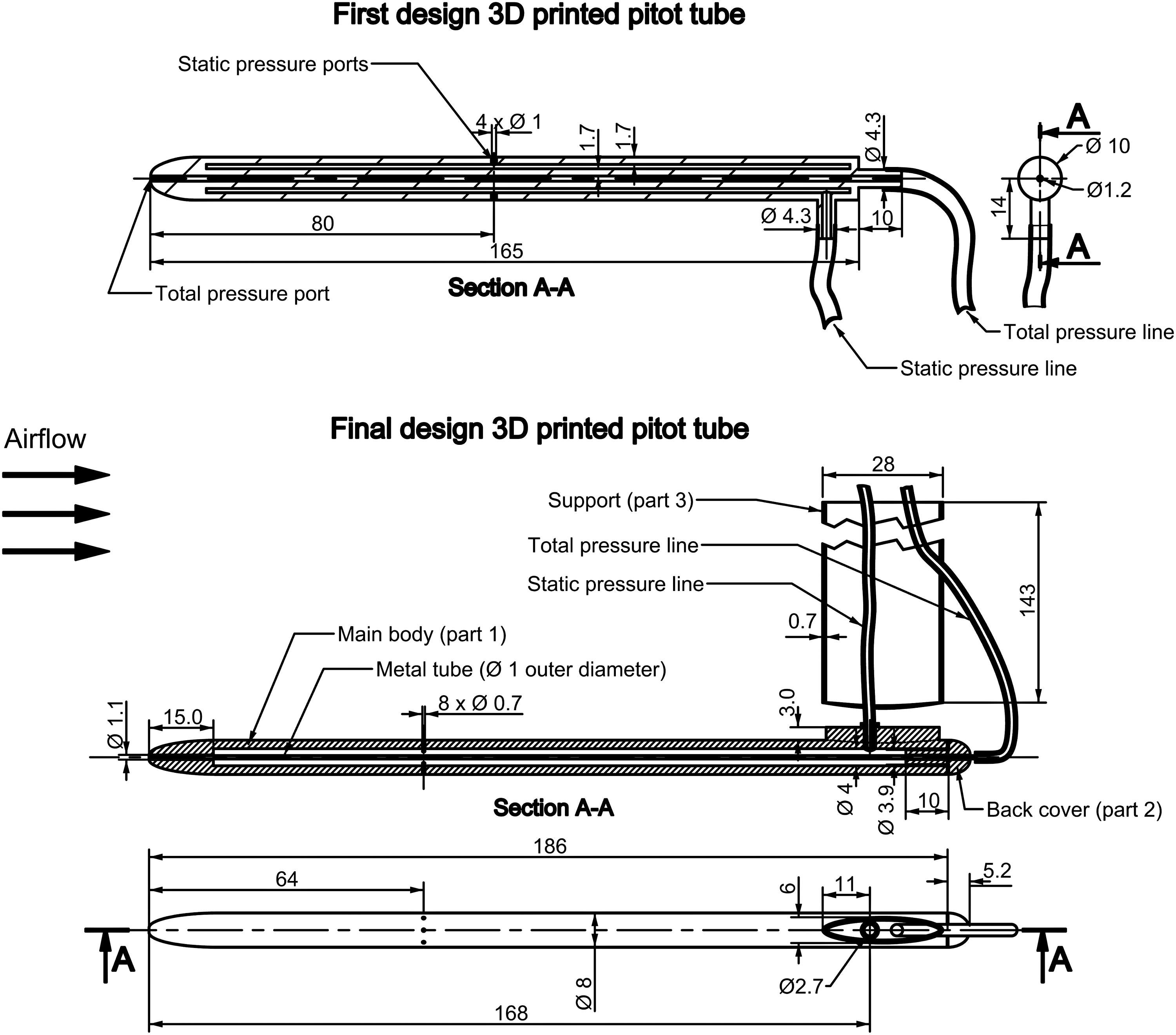
First and final designs of the 3D printed Pitot tubes.
Several problems in the 3D printed part were immediately apparent, as the static port holes were not manufactured correctly, with two of the holes being closed and needing to be opened with a 1 mm diameter drill, the maximum recommended value. 22 In addition, the static port holes that came out open did not have a regular shape due to the limited resolution of the printing machine, and they needed drilling to make them round. Another issue found was the blockage of both pressure lines due to the support material not being completely removed by the WaveWash machine.
The total pressure line was fairly easy to clear with a steel wire due to its straight geometry, whereas the static pressure line was much more problematic to unblock due to its convoluted path, finally being cleared after a laborious process with the repeated use of compressed air and several prolonged stays in the WaveWash machine.
Once both pressure lines were unblocked, the Pitot tube was immersed in water, and air was blown through each pressure line to search for possible leaks in the form of air bubbles, with no problems being found by this inspection process. The 3D printed probe was then tested in the wind tunnel against a reference metal-constructed Pitot tube at wind speeds ranging from 2.1 to 31.5 m/s. The results are shown in Figure 4 by the data points labeled “basic.” It can be observed that the airspeed values obtained with the 3D printed probe are always inferior to those measured with the reference Pitot tube, with the slope of the matching curve being 0.872.
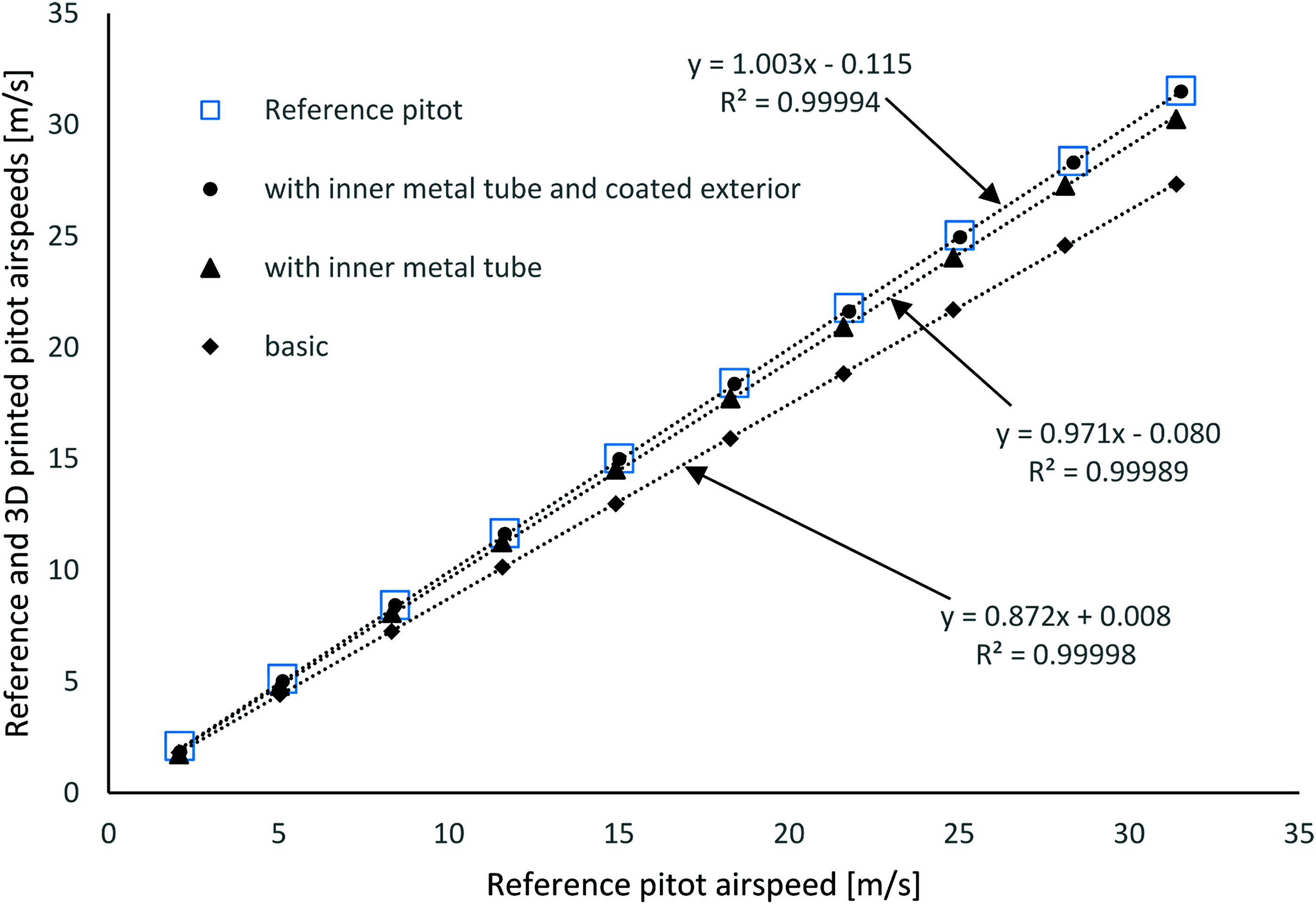
Comparison of the airspeed measurements of the first design of a 3D printed Pitot tube, at various stages of evolution, with those of a reference standard construction metallic Pitot tube. Color images available online at www.liebertpub.com/3dp
The source of this problem was not clear since no leaks were detected in the water immersion test. Nevertheless, there was a suspicion that wall porosity could be at the root of the problem and, therefore, it was decided to install a metallic tube with a 1 mm external diameter inside the total pressure channel of the 3D printed Pitot tube, to first investigate the contribution of the total pressure leakage to the errors in airflow speed measurement.
The 3D printed probe with the inner metal tube was tested against the reference instrument and, as shown by the triangle markers labeled “with inner metal tube” in Figure 4, the obtained results are now much more closely matched to the reference Pitot tube, with the slope of the matching curve now being 0.971. Since the 3D printed probe still consistently underestimated the airspeed, a second modification was made, this time consisting of sealing its outer surface with a resin coating 15 followed by fine sanding to achieve a smooth surface.
Due to the resin coating, the static pressure holes became closed and had to be reopened with a 1 mm drill. In this final configuration, the 3D printed Pitot probe was again tested against the reference instrument. This time, the matching of the airspeed readings between the two devices was almost perfect, as can be observed in Figure 4 by the data labeled “with inner metal tube and coated exterior,” the slope of the matching curve being 1.003.
Microscopic and mechanical analysis of the 3D printed parts
To better understand the origin of the air leakages, uncoated and coated 3D printed Pitot tubes were sectioned and observed on a Leica™ MEF4M optic microscope, the resulting images being presented in Figure 5. This figure also shows the locations where the cross-sections were imaged. In image A of Figure 5, the cross-section of the outer shell of an uncoated Pitot tube is presented, where it is visible that there are gaps in the outer layers of filaments, and that air passages are possible in its interior region. In image B, a lengthwise section of the outer shell of an uncoated Pitot tube is depicted, showing multiple possible air channels in its inner region. The cross-section of the outer shell of a coated Pitot tube is presented in image C of Figure 5. In this image, the outer resin coating is visible, and its necessity was once more made clear due to the observable gaps between filaments.
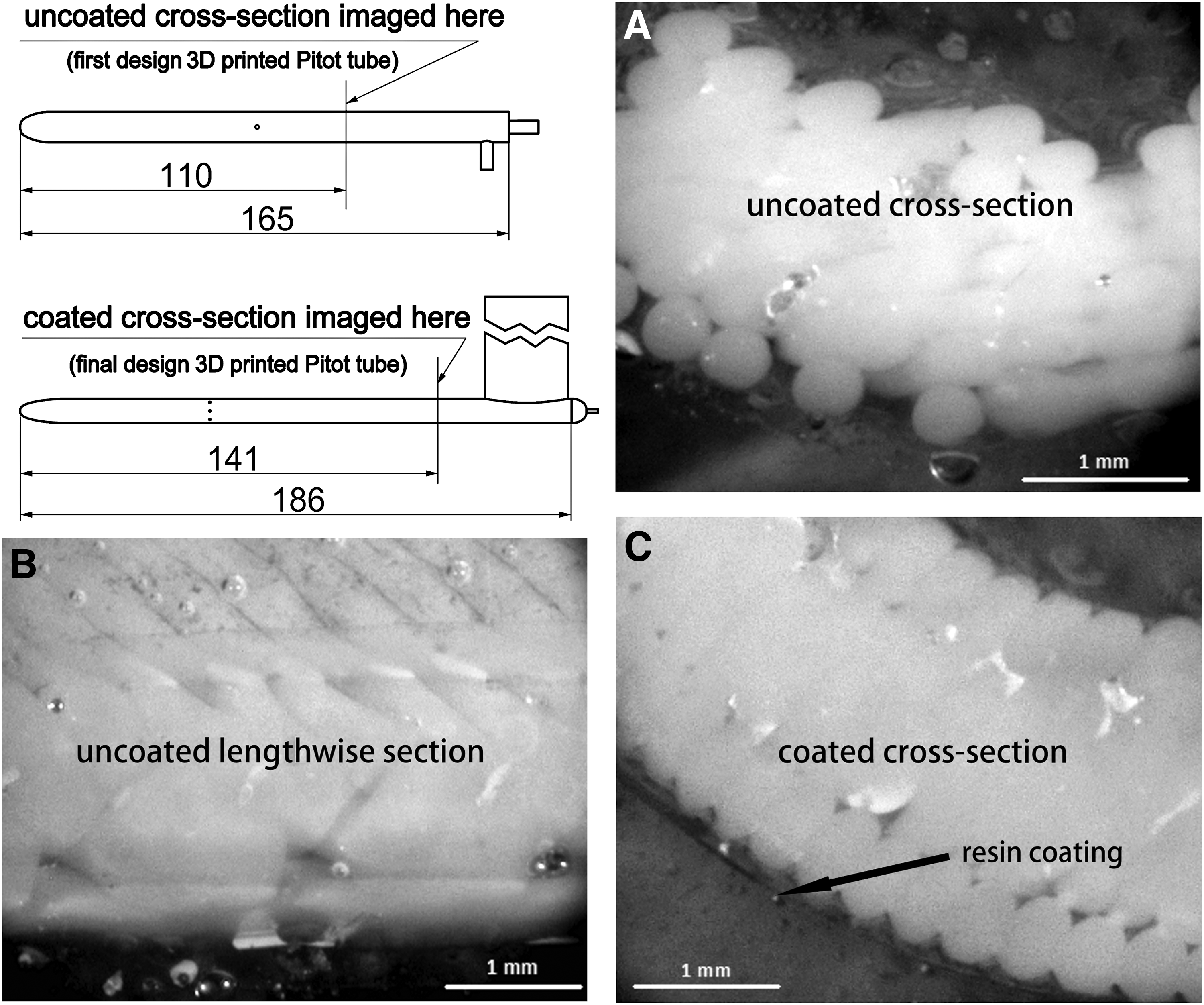
Microscopic imaging of sections of uncoated and coated 3D printed Pitot tubes. The cross-section of the outer shell of an uncoated Pitot tube
Some mechanical properties of the uncoated and coated 3D printed parts were measured in a Shimadzu™ AGS-X test machine. The tensile strength obtained for the uncoated parts was 46.6 and 61.0 MPa for the coated parts, thus exceeding the advertised value of 33 MPa. Diametric compression strength tests were also performed, with the results being 0.51 and 3.19 MPa for the uncoated and coated parts, respectively. Both results show that along with the air sealing, the coating also had the benefit of increasing the mechanical resistance of the parts.
Final design of a 3D printed Pitot tube
Several important lessons were learned with the first attempts at producing a 3D printed Pitot tube, and modifications were incorporated into the final design, presented in detail in Figure 3. The first change was the incorporation, from the beginning of the design process, of the inner 1 mm diameter metal tube to measure the total pressure, due to the leakage problems encountered with the original design, and the physical impossibility of coating the total pressure channel after the single-part 3D printed Pitot tube was produced. Another difference relative to the original design was the creation of a main body (part 1 in Fig. 3) with an open rear end, this feature resulting from the necessity of an easy access to the interior of the part to remove the remains of the support material.
The open end of the main body created the need for a separate back cover (part 2 in Fig. 3) with a central hole for the passage of the metal tube. As a result of the small diameter of the inner metal tube, the outer diameter of the 3D printed Pitot was decreased from 10 mm (in the first design) to 8 mm, which was desirable to reduce the intrusive character of this measuring device. Due to the already mentioned difficulties of the 3D printer to produce the small-diameter static port holes, it was decided to remove them from the CAD model and drill them later, this time with a smaller diameter drill (0.7 mm) due to the also smaller outer diameter of the main body. A third part of this 3D printed Pitot probe consisted of a thin-walled (0.7 mm) support (part 3 in Fig. 3) that allowed the passing of the pressure lines inside it. The assembly of the parts was achieved by gluing them with cyanoacrylate adhesive.
Both the main body (part 1) and the back cover (part 2) were air sealed by resin coating their outer surfaces, and they were later sanded to achieve a smooth finish. This final design of a 3D printed Pitot tube was also tested against the reference instrument, the results being presented in Figure 6. An excellent match can be observed between the airspeed measurements obtained by both instruments.
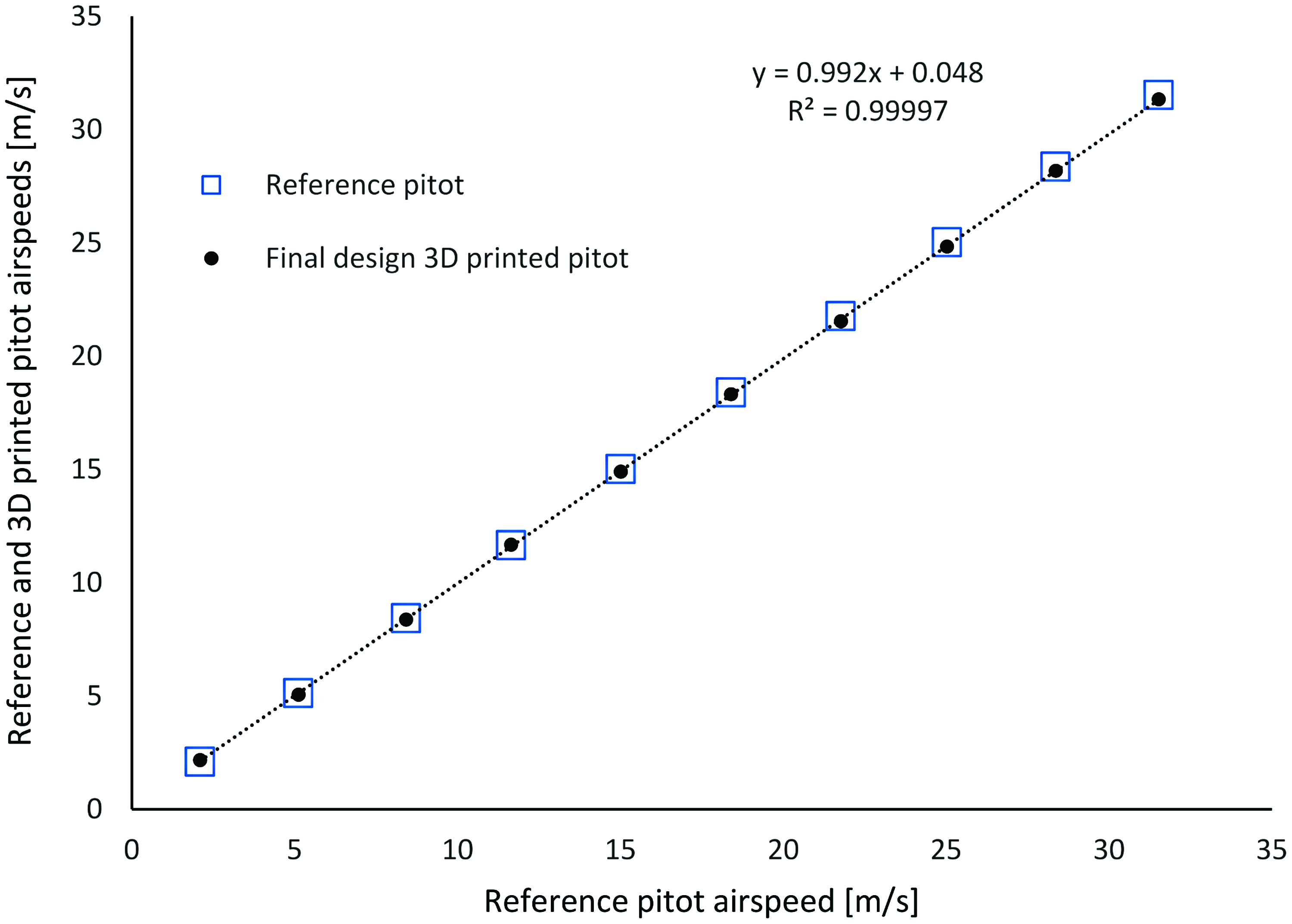
Comparison of the airspeed measurements of the final design of a 3D printed Pitot tube with those of the reference standard construction metallic Pitot tube. Color images available online at www.liebertpub.com/3dp
Pressure-Enhancing 3D Printed Pressure Anemometers
Design of the pressure-enhancing probes
As stated in the Introduction, a shortcoming of Pitot tube anemometers is that the pressure signal produced at low speeds, typically below 4 m/s, is quite small. 11 To enhance the pressure signal from these probes, due to the impossibility of increasing the total pressure, the strategy to follow is to devise aerodynamic shapes that lead to a local decrease of the static pressure at the respective ports' location, thus increasing the pressure differential, that is, the pressure signal. A drawback of pressure-enhanced probes is that, contrary to Pitot tubes, Bernoulli's principle of energy conservation can no longer be directly applied, as the static pressure measured is no longer that of the free flow. Due to this fact, the pressure signal is not a direct measure of the flow speed and, as such, each device needs a dedicated calibration against a reference instrument.
To help the shape exploration process of the enhanced signal pressure probes, computational fluid dynamics (CFD) simulations were performed with the EasyCFD™ software in an axisymmetric configuration and for an airflow speed v = 1 m/s, as it is at low speeds that it is more important to increase the pressure signal.
The different pressure-enhancing probe geometries built and tested are presented in Figure 7. All probes and add-on parts were resin coated to make them airtight and later sanded to achieve a smooth surface finish. In probe S1 of Figure 7 (part C in Fig. 1), the main body was itself special shaped; whereas in probes S2 and S3, special-shaped rings (part F in Fig. 1) were inserted before and after the static ports of the final design 3D printed Pitot tube to create an airfoil-like cross-section. The rings were sanded in their inside surface until a tight fit with the Pitot tube's surface was achieved, thus avoiding permanent fixing with glue.
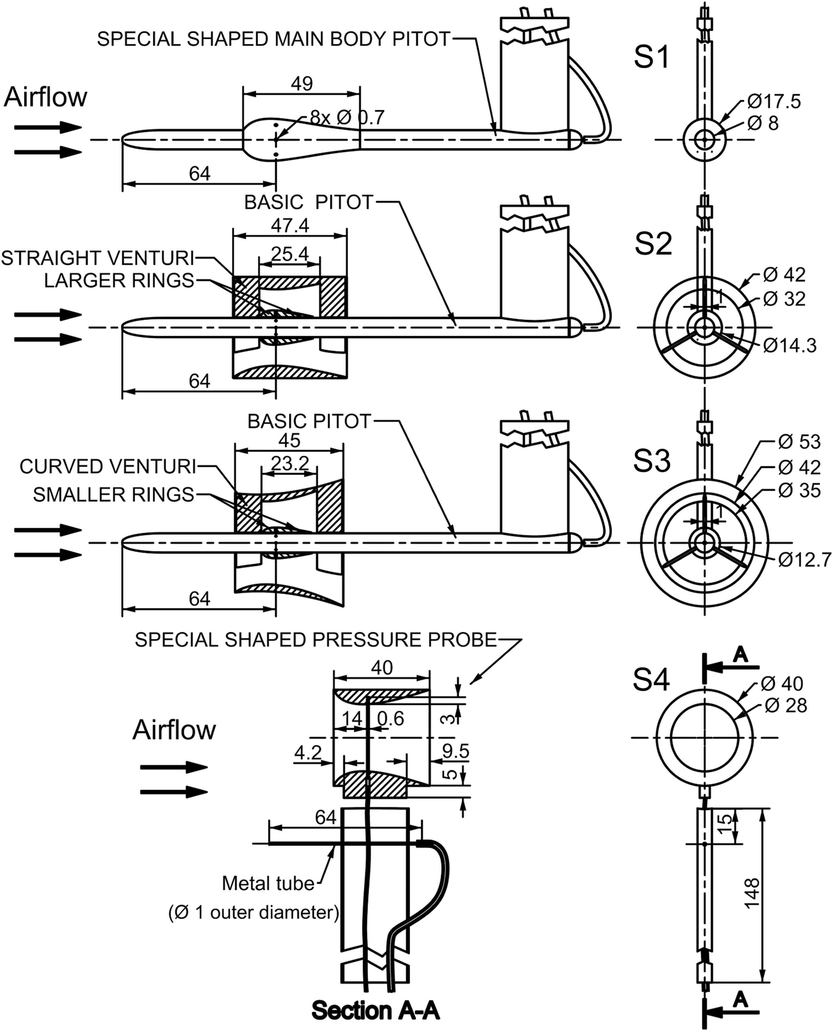
Special-shaped 3D printed pressure-enhancing anemometers. The main body of a special shaped Pitot
Two sets of rings were built and tested, one with an outer diameter of 14.3 mm and the other with 12.7 mm. In an attempt to further enhance the pressure signal, two venturi-shaped parts, shown in a cross-sectional view in drawings S2 and S3 of Figure 7 (part E in Fig. 1), were designed, one with a straight and the other with a curved outer shape. The venturis were easily installed around the special-shaped rings by slightly forcing them into place while lightly bending their supporting fins. Once inserted in a Pitot tube, the venturi was kept in place during the wind tunnel tests by its contact with the front ring.
The last design investigated is depicted in drawing S4 of Figure 7 (part D in Fig. 1). In this probe, the total pressure is captured by the protruding 1 mm outer-diameter metal tube; whereas for obtaining the static pressure, instead of holes, a small slot (visible in Fig. 1) with a width of 0.6 mm and a depth of 3 mm is employed. The use of a slot instead of holes for capturing the static pressure is not original, having been successfully employed previously. 11
Due to the large number of pressure-enhancing probe geometries investigated, a summary of all configurations tested is presented in Table 2.
The CFD simulations provided an invaluable insight into the flow's behavior around the probes, effectively helping in the design process. In Figure 8, pressure isocurves and their value at the static ports location are presented for all geometries investigated, except those involving the smaller rings, cases 3, 5, and 7, as they produced results similar to the larger rings. Observing Figure 8, it can be seen that the special-shaped main body Pitot (case 1) and the use of rings alone (case 2) do decrease, to some extent, the pressure at the static ports location, and that adding a venturi (cases 4 and 6) greatly increases this effect, with the curved venturi more effective than the straight one.
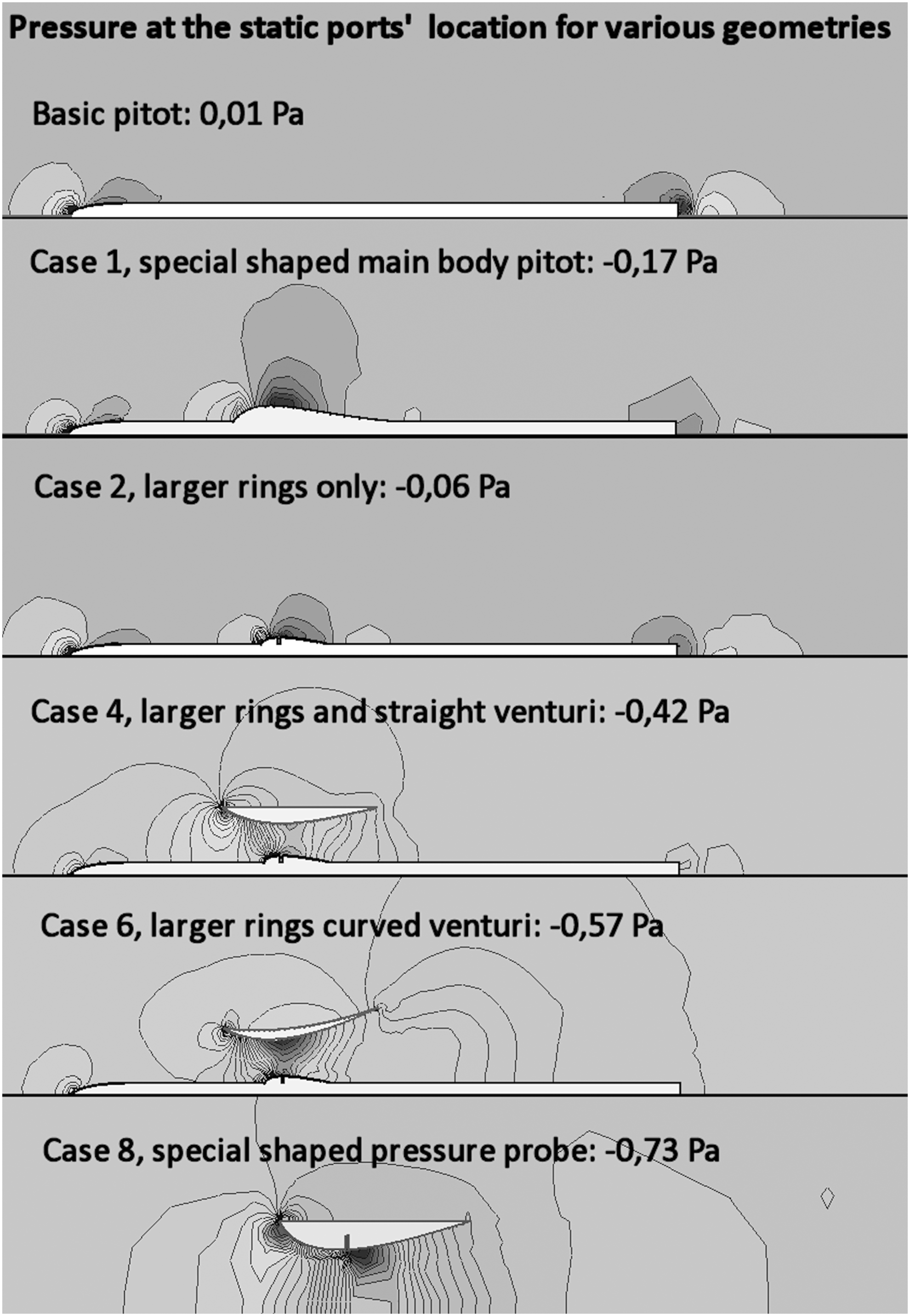
Computational fluid dynamics simulations of the static pressure distribution at v = 1 m/s for all pressure probe geometries studied except cases 3, 5, and 7.
The CFD results were confirmed by the wind tunnel tests except for case 8, the special-shaped pressure probe, whose pressure gain was lower than expected.
Wind tunnel testing of the pressure-enhancing probes
Despite advances in CFD, due to the still unfound solution for the equations that describe fluid flow, one of the unsolved problems in Physics, 23 experimental validation of CFD results is still usually necessary, 24 with experimental data being pivotal in the final decision of freezing a design. 25 Accordingly, wind tunnel tests of all pressure-enhancing probes were performed. The evolution of their pressure signal with airspeed, as well as that of the final design 3D printed Pitot tube (basic Pitot), is presented in Figure 9.
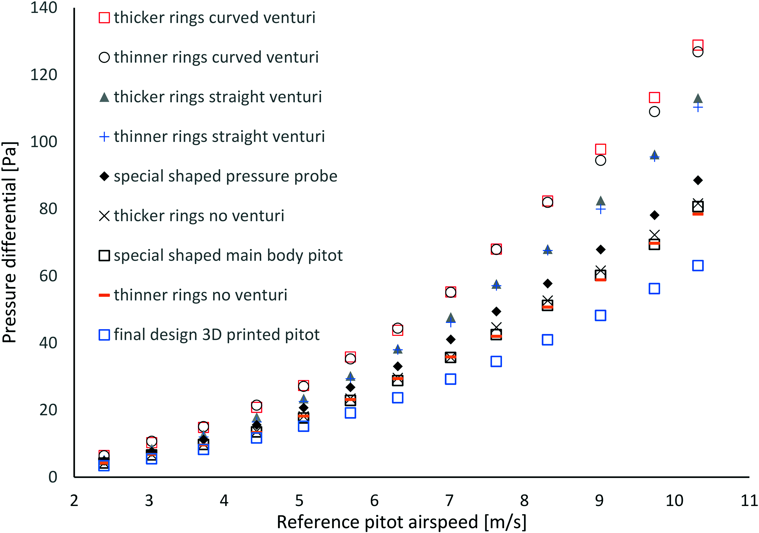
Variation of the pressure signal with airspeed for all pressure-enhancing probes investigated and the final design 3D printed Pitot tube (basic Pitot). Color images available online at www.liebertpub.com/3dp
As can be observed, the global shape of the curves is the same for all geometries tested and fairly regular, showing that a working calibration would be easy to obtain. The greatest signal gain was achieved with the use of add-on rings and a curved venturi, cases 6 and 7 of Table 2, more than doubling the pressure signal of the standard 3D printed Pitot tube. The special-shaped pressure probe, case 8, produced a pressure gain that was much lower than expected from the CFD simulations, probably due to manufacturing imperfections in the slot that captures the static pressure.
It is important to stress that even if the final working pressure-enhancing anemometers were not intended to be manufactured by 3D printing, prototypes with their complex geometries had to be made for wind tunnel testing. This is an area where the present work confirms that additive manufacturing brings remarkable benefits, as the fabrication of aerodynamic models for wind tunnel tests is traditionally a complex, time-consuming, and expensive task, whether performed manually or with the help of CNC machining. 26
Conclusions
The porosity existing in parts produced by the 3D printing FDM manufacturing process is a severe drawback when trying to produce pressure anemometers. It is possible to circumvent the lack of airtightness in the parts with a surface coating and an adequate design, but, for devices with a simple geometry like Pitot tubes, FDM does not present clear advantages over traditional metallic construction methods.
In contrast, where 3D printing was found to excel, even with the porosity issues of FDM, was in the development of complex-shaped pressure anemometers that produced an enhanced pressure signal, due to the freedom of shape, complexity at no added cost, and speed of prototyping that 3D printing allows. In this endeavor, results from CFD simulations of the pressure distribution along the probes provided very helpful guidance during the shape exploration phase of the design process.
Eight different pressure-enhancing probe geometries were wind tunnel tested, the best performer being a conventional-shaped Pitot tube with 3D printed add-on parts applied, a configuration that more than duplicated the original pressure signal. This is an important finding, as it shows that bespoke designed 3D printed parts can be added to existing standard metallic construction Pitot tubes to increase their pressure signal.
Finally, additive manufacturing, in general, even with the added step of sealing the parts needed by some techniques, namely FDM, proved to bring considerable advantages in the making of functional aerodynamic parts for wind tunnel testing, a traditionally complex and costly task when performed by more conventional manufacturing processes.
Footnotes
Acknowledgments
This work is framed within the Energy for Sustainability Initiative of the University of Coimbra and LAETA (Associated Laboratory for Energy, Transports and Aeronautics) Project UID/EMES/50022/2013. The second author wishes to acknowledge the Portuguese funding body FCT—Fundação para a Ciência e a Tecnologia for partially supporting his research through the PhD grant SFRH/BD/77911/2011.
Author Disclosure Statement
No competing financial interests exist.