
Abstract
Abstract
Fused deposition modeling deposits a filament layer by layer and according to a trajectory. Based on stress criterion for filament deposition, this work suggests reproducing the principal directions of the stress in the sample through the control of the filament direction. A number of compact-tension (C-T) specimens have been printed with and without respecting this criterion. The fracture toughness test of these specimens was realized to compare the results. The results show that the suggested criterion leads to an improvement of 30% in the fracture toughness. Digital images correlation has been extensively used to study the local strain field in the specimens. Strain mapping reveals an important change in fracture behavior. The modification of filament direction leads to “ductile-like behavior” in crack extension, which is characterized by a large deformation zone associated with a slow crack growth rate during crack propagation.
Introduction
EPF (Graduate School of Engineering) and UTT (University of Technology of Troyes) in France work on a new stress-based criterion for filament deposition in fused deposition modeling (FDM). According to this criterion, the filament directions follow the principal directions of the stress in the sample. The objective is the manufacturing of a “smart material” allowing to enhance the fracture resistance when a V notch or crack exists in the specimen. The procedure is to determine the stress field in the specimen by use of finite elements (FEs) simulation analysis. Compact tension (C-T) sample reproduces the principal stress directions inside the internal structure realized by fused deposition in three-dimensional (3D) printing to improve the fracture toughness. The study analyzes and compares the outcomes of C-Ts performed with classical and optimized filament depositions. The strain field close to the geometrical singularity is measured by digital image correlation (DIC). The challenge is to reinforce the structure of acrylonitrile butadiene styrene (ABS) parts so that increase or adapt some products to industry for master the safety and the mechanical impact of the new structure printed by Additive Manufacturing (AM). Many technologies have emerged from AM and depend on material and its hardening system as the sintering or melting by laser, the binder or resin jetting, or filament depositing. 1 From one technology to another, the manufacture direction, the model orientation, and the material behavior are important to get an accurate model and an efficient production. 2 Among these technologies, FDM is a layer AM process that uses a thermoplastic filament by fused deposition, which builds its geometry along trajectories generated by slicing.
Generative Trajectory of 3D Printing
FDM process, also known as fused filament fabrication, begins with a 3D model in CAD or modeling software before converting it in *.stl format file. This format is treated by specific software owned by AM technology that cuts the piece into slices to get a new file containing the information for each layer. This step implies a G-code language to transform the slicing in trajectories and layers. During manufacturing, a filament is extruded through a nozzle to print one cross section of an object, then moved up vertically to repeat the process for a new layer (Fig. 1). Through this deposition, the filament trajectory is defined to fill the product and also to create a shell with often a stripe shape at 45° by alternate layers. The most used materials in FDM are ABS, polylactic acid, and polycarbonate. To predict the mechanical behavior of FDM parts, it is critical to understand the material properties of the raw FDM process material, and the effect that FDM build parameters have on anisotropic material properties. 3 About the internal structures of products realized by 3D printing, some studies such as 4 investigate the use of lattice structures, including rapid prototyping to lighten sandwich panels while maintaining their mechanical strength. The study enabled to determine that the directions of the anisotropy of the lattice influences the mechanical behavior of the entire panel used. The lattice modeling can be adjusted according to the specifications of mechanical strength. Other studies develop specific structures such as curved, 5 honeycomb 6 or cell shapes, “tetrachirales,” 7 or “hexachirales.” 8 Studies develop and characterize 3D scaffolds manufactured by deposition to control structure so that to modulate mechanical properties.9,10 Some original researches suggest to adapt the internal structure based on mechanical constraints like a method for generating specific infill structures based on rhombic cells so that the resultant structures satisfy manufacturing requirements. 11 Other works suggest optimizing the filling patterns to follow the optimal deposition direction to enhance the mechanical behavior. 12 Today, topological optimization is also a strong track that suggests other internal structure in AM 13 where the FDM technology is used.14,15 None of those studies use principal directions from FE to reproduce them through 3D printing trajectories, and mechanical behaviors have not been investigated. This research used Makerbot Replicator 3D printer to manufacture the specimens in ABS material with a printing configuration mainly defined by a layer thickness of 0.2 mm and an extrusion nozzle diameter of 0.4 mm. 16

Description of the study steps presented as a chart: Step 1 including
To fulfill the conditions proposed, the filament must follow the principal direction of the stress tensor when the principal stresses are mainly tensile. Therefore, the force lines in the material will be guided by the filament. As two principal directions exist, two directions must be considered. Filament deposition will be performed subsequently according to each direction. FEs simulation of a linear elastic model has been used to compute the principal stresses and strains in the sample with plane stress conditions. As the in-plane stress is biaxial, there are two principal directions in the sample. Therefore, two trajectories are to be considered in the printing. For this reason, the thickness dimension of the sample is built by alternate layers. For two subsequent layers, the first (second) principal direction is used to calculate the trajectory in the first (second) layer as shown in Figure 1a and b.
To improve the mechanical properties of a printed sample, the polymer threads must be oriented toward the tensile force field (or traction stress) in the sample. This idea is inspired from the reinforcement principle of the composite materials wherein the fibers are oriented toward the in-plane tensile stress.
The principal directions are computed as previously described at each point in the sample. These directions (eigenvectors) are tangent to the printing trajectory. As the in-plane stress is biaxial, there are two principal directions in the sample. To reproduce directions from FE and generate a G-code of those two different layers, the Slic3r software is used (slic3r.org). The method uses a geometry definition of high-stresses pattern on the C-T sample for layers 1 and 2. Then, a 100% concentric infill is applied for layer 1 to reproduce the first trajectory and a 100% alternating 45° infill is realized to reproduce the second related trajectory for layer 2. The result of this method is shown in Figure 1b and c. The method is limited to a two-dimensional (2D) pattern suitable with C-T sample like an orthogonal projection of stresses area. The printing parameters are summarized in Table 1:
3D Printing Parameters in the Software
FE, finite element.
Therefore, two trajectories are to be considered in printing. To reproduce the trajectory by 3D printing, the approach used G-code that is the common programming language used for the most widely used numerical control.
3D Printing of Samples
The slicing of 3D model (in *.stl format) is applied with concentric fill pattern around the delimited zone according to crack simulation. The printing trajectory must agree with the principal direction in the delimited zone (Fig. 1a). The other “white” domain is less stressed (in the tensile direction) and is printed without respecting the principal direction conditions. The G-code is modified to alternate the layers with the principal direction and the less stressed direction. The depositing trajectory shows a drawing of the thread close to stress fields' results.
To compare classical and optimized samples, two types of standard compact tension (C-T) specimens are designed according to the standard ASTM E399 17 with a dimension 75 × 75 × 4 mm and printed. The first “classical” sample is got by linear infilling with 45° depositing by alternate layers and the second “optimized” sample uses the previous generative trajectory method (Fig. 1c). The 3D printing was of half past 1 h for a classical sample and 22 min past 3 h for an optimized one.
Experimental Approach
2D DIC is used to study the strain mapping to compare the results with the numerical simulation. The C-T specimens were painted with specific pattern (Fig. 1d) to distinguish the displacement of each domain on the sample surface.
The tests procedure was used with the crack test samples fabricated with the MakerBot Replicator. A tensile test machine Instron 4484 was used to carry out uniaxial tensile tests with a specific tensile tool for the crack tests adapted to specimens (Fig. 2d). The displacement speed of the machine was 1 mm/min with a sampling period of 500 m/s. The load cell capability is 150 kN and the procedure used three samples each for “classical” and “optimized” models without DIC and two samples each for DIC.

Crack test results, force–displacement curves for classical printing samples
After the cracking tests, the results show fracture propagation from the notch. The “classical” samples have a straight fracture due to alternating layers with a thread deposit at 45°. The “optimized” samples have a dendritic fracture with a dispersion of the stress field localized into the zone that reproduces the principal directions to resist to crack propagation.
The resulting force–displacement curves are compared in Figure 2. The curves exhibit several regimes. The force growth is perfectly linear for the classical sample, whereas it is curved for the optimized sample. At the end of this regime, a crack is triggered at the V notch tip. The onset of the crack limits the force growth. The crack extension leads to a force decrease. This behavior is confirmed by the DIC analysis of the sample as shown in the following paragraph.
For both classical and optimized samples, the results were compared and they are summarized in Tables 2 and 3. The study notes that the critical stress intensity factor (SIF) “KIc” of the C-T samples is calculated according to the standard ASTM E1820
18
:
where “P*” is the force at which the crack is initiated, “B” is the sample thickness, “W” is the sample width, “a” is the crack size, and “
Mechanical Results of Optimized Samples
C-T, compact tension; SIF, stress intensity factor.
Mechanical Results of Classical Samples
According to these results, the optimization of printing leads to a considerable improvement in the critical SIF KIc of the specimens.
For the classical samples, the averaged value of the critical SIF is 3.48 ± 0.3 MPa.m0.5, whereas it reaches 4.36 ± 0.25 MPa.m0.5 for the optimized samples. The optimized samples are clearly stronger than the classical samples through an adequate printing. The optimized C-T samples have higher fracture strength up to 30% than classical samples.
To understand well the different regime of the crack behavior, C-T deformation has been followed by DIC. Figure 3 shows the force–displacement curve with the corresponding enumerated snapshots for optimized and classical samples. The ɛyy strain field is shown within these snapshots. To facilitate the comparison, same color-bar range is used for all snapshots. When force increases with respect to displacement, strain increases in the sample and becomes more concentrated close to the V notch tip (red color zone). The crack initiates when the force reaches a maximum value. The crack extension leads to sample bifurcation, therefore, geometrical discontinuity appears in the figure. The correlation cells within the discontinuity region are removed from the region of interest by the DIC software. Therefore, the crack zone appears without being colored by the color palette. This manipulation helps one to distinguish the crack path.
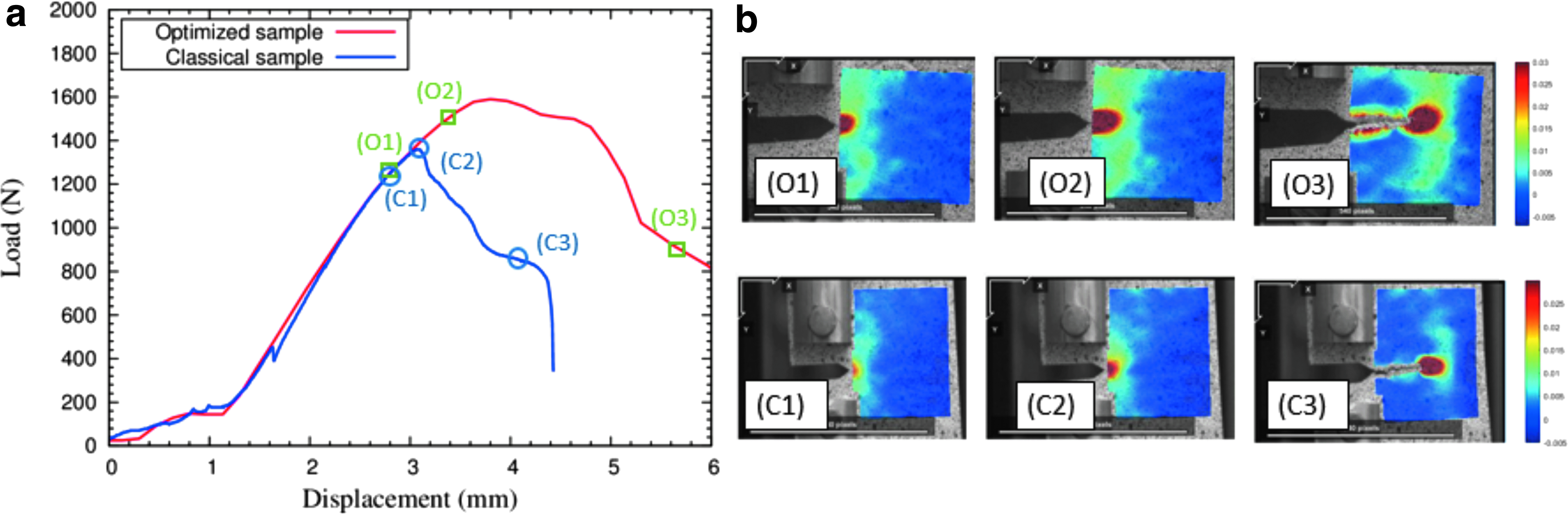
Crack test results: comparison between optimized and classical samples.
Snapshots (O2) and (C2) in Figure 3b are taken before the crack initiation in the samples. The strain (stress) concentration at the notch in the classical sample is still very local compared with that in the optimized one. The material is slightly affected by the stress concentration. Furthermore, there is no apparent plastic deformation observed close to the crack borders in the classical sample after the crack extension (snapshots O3). These observations confirm that the behavior of the classical sample is like a brittle crack behavior.
In contrast, the fracture behavior observed in the optimized sample reproduces somewhere the scenario of a “ductile-like” fracture extension. However, this ductility is not an inherent property of the constitutive ABS copolymer of the C-T sample. This “pseudo-ductility” results from a judicious orientation of deposited filaments. The behavior is then like a fictitious ductile one.
Conclusion
A new stress-based criterion for filament deposition in FDM 3D printing has been suggested and tested. According to this criterion, the deposited filaments by 3D printing are oriented toward the principal directions of the stress. Several crack test samples have been printed following this criterion “optimized sample” and the commonly used printing methods “classical sample.” These samples were manufactured according to a G-code generation method and subjected to a C-T test. The results show a remarkable improvement through average values of the critical SIF with a fracture toughness about 30% of the sample printed according to the suggested criterion. DIC has been employed to study the strain field of the samples. These observations highlight a drastic change of fracture behavior. The modification of filament direction leads to “ductile-like behavior” in crack extension, which is characterized by a large deformation zone associated with a slow crack growth rate during crack propagation. Therefore, the propagation leads to a loss of strain energy. At the end, new possibilities can be envisaged by applying this method to other geometries to master the risk of fracture from 3D printing structures. The G-code generation is adapted to a 2D pattern from an orthogonal projection of principal directions. A complex geometry with a stresses repartition in 3D requires an improvement of this method.
Footnotes
Acknowledgments
Thank you to “Grand Est,” “Troyes Champagne Metropole,” and “Conseil General de l'Aube”.
Author Disclosure Statement
No competing financial interests exist.