
Abstract
Abstract
This article is the first in a two-part series describing a process for conformal three-dimensional (3D) printing on to inflatable substrates. Details for fabricating seamless, tubular elastomeric membranes by spray deposition on a double-curved air-permeable mandrel are presented in Part I. The mandrels are created by casting gypsum into a desired form, and they are made permeable by applying pressurized air to the central core of the gypsum body during its crystallization phase. The membranes—in this case made from silicone—are created by spray deposition onto the mandrel by using a constant surface angular velocity approach. These membranes are inflated so as to impart mechanical pre-strain in the rubber by stretching. The techniques described are particularly suited to the fabrication of 3D printed pneumatic artificial muscles and dielectric elastomer actuators. They can also be used to create removable substrates on which a 3D print can be extruded, or alternatively integrated into a four-dimensional print where varying levels of mechanical strain can be distributed through the various printed layers. Uses for the techniques described include soft robotics, stretchable electronics, biomechanical implants, and custom bioreactors, particularly when combined with direct ink writing techniques.
Introduction
T
Described here is a low-cost method to create air-permeable mandrels, on which spray deposition is used to fabricate thin silicone elastomer membranes of even thickness. These membranes are inflated by passing air through the mandrel. The resulting mechanically strained member is measured by a triangulation laser. Patterned collapsible (auxetic) tessellations are calculated over this double-curved inflated surface and converted to computer numeric control toolpaths. Multiple layers of a hard (Shore 73A) silicone are extruded over and bonded to the stretched substrate. When the entire structure has crosslinked and bonded together, the compressed air is removed. The structure deflates, transferring strain energy from the membrane to the extruded frame, until settling in a minimum energy form.
Petralia and Wood 2 gave an in-depth description of DEMES fabricated by laminating two-dimensional planar layers under differing levels of tension and compression and allowed to buckle out of plane. These out-of-plane buckled structures were described as difficult to model, particularly when trying to anticipate their resting shape in minimum energy form. In part, this was because the hand-made aspects of these structures resulted in a non-uniform strain being applied to the hand-stretched membranes. This was exacerbated by application of an arbitrary-shaped pliant planar frame to that membrane. Building on their concept, it is the desire of this series of papers to demonstrate DEMES using custom-fabricated balloons with extruded auxetic support frames that collapse in a more regular and predictable way.
Spray deposition of polydimethylsiloxane (PDMS) membranes via atomization by using pressurized air is discussed in Ref. 3 Here, silicone dielectric elastomer actuators (DEA) were created by spraying dichloromethane diluted silicone (Sylastic 3481) onto the straight edge of a rotating wheel. Long tape-like membranes of consistent thickness ranging from 40 to 160 μm were created. The authors discussed the principles of using overlapping spray lines to create a constant membrane thickness over a wide but flat area. This article seeks to investigate how to go further by spraying on double-curved rotating surfaces. Planar PDMS pattern creation by airbrush was also discussed in Chooneea et al. 4 Fabrication of tubular membranes for dielectric elastomers via dip coating was proposed in Pelrine et al. 5 and Carpi and De Rossi. 6
Pre-stretching an elastomer membrane increases the surface area while reducing the thickness. The result is stored strain energy in the elastomer, along with a thinning of the membrane. The change in material properties resulting from pre-stretch, known as stress softening or the “Mullins effect,” is discussed and tested in Johnson and Beatty. 7 Elastic strain energy from stretching tends toward returning to its un-stretched state if not constrained in some way. Methods to hold a strained elastomer from collapse included wrapping around a compressed spring, 8 pliant incompressible planar frames, 8 conical diaphragms, 9 shell-like actuators, 10 and inflated balloon-like implementations. 11 Beyond adding elastic energy, it has been shown that pre-stretch increases the dielectric breakdown strength by up to one order of magnitude.12,13 This is particularly important in the fabrication of DEA.
Balloon actuators were created in Soleimani and Menon 11 and Potz et al. 14 by rolling up and gluing of planar elastomer membranes into cylinders, then inflating with a hose. Such fabrication methods are seen as sub-optimal, due, in part, to the presence of and the inherent weakness of seams; this prevents achieving high levels of pre-strain without the “balloon” rupturing. Also, such seams inhibit the symmetrical equibiaxial growth of the balloon form during inflation.
Arbitrary-shaped balloons were created by using casting methods for spherical balloons using a five-part spherical mold. 15 Problems such as variation in membrane thickness of ±50 μm arose from the tolerances of the three-dimensional (3D) printer used to fabricate the mold. 16 Flat pneumatic artificial muscles were created in Park et al., 17 by pour casting flat sheets, and strengthening by embedded Kevlar fibers.
This article seeks to form a balloon as a single membrane by using an additive manufacturing aerosol process. The only requirement is a positive mold (mandrel) on which to deposit the membrane. This mandrel is fabricated to be air permeable, so it can act as an inflation mechanism, and therefore act as a departure point for balloon inflation. This obviates seams and allows for much greater flexibility in initial balloon shape. Emphasis is placed on creating the smoothest surface mandrel with the highest porosity possible—this encourages equal strain softening on all parts of the balloon membrane during inflation, thus resulting in the most axially symmetric inflated substrate as possible.
There are a number of materials from which a permeable inflating mandrel can be created: sintered metal or glass powder, porous polymer, or mineral substrate. Perhaps the quickest method with lowest cost is achieved by casting the mandrel from mineral calcium sulfate (gypsum). The porous properties of the crystallized hemihydrate form of calcium sulfate have long been known and are well defined.
A method described in Bryer and Steele 18 discusses persistent permeability in a plaster body. The authors state that it is preferable to utilize a minimum of water in the plaster mix for the most porous and the longest wearing gypsum preparation. This makes the material more difficult to handle when casting. Instead, an excess of water is generally used to remove air bubbles and to achieve a superior surface finish. The excess water, that is, water not required for the conversion reaction from hemi-hydrate to the dehydrate form is referred to as “held water” due to its retention in the crystallized matrix. The authors found that when compressed air was injected into the center of the main body (core) of the mold, it forced most of the held water to percolate out to the surface. This imparted a significant permeability to the final body. It was necessary to carry out this procedure after the “initial set,” but before the “final set” when the gypsum reached stable crystallization. Both α and β forms of gypsum can be used; both these will then exhibit a stable and permanent permeability and a marked improvement in the stabilization of the outer surfaces against structural deterioration.
Materials and Methods
Fabrication of a permeable mandrel
To create a mold for casting the gypsum mandrel, an axially symmetric “cigar” shape was drawn on CAD and produced on a CNC lathe by using Necumer M1050, a high-density polyurethane “chemiwood” (Fig. 1b). This shape was chosen arbitrarily. The shape was used as a mandrel “positive,” that is, a positive form was cast, allowing creation of a seamless single-sleeve negative mold into which gypsum could be poured to create a permeable mandrel. The sleeve mold was composed of a low Shore hardness silicone. (Smooth-On Ecoflex 00-30). This is shown in Figure 1f.
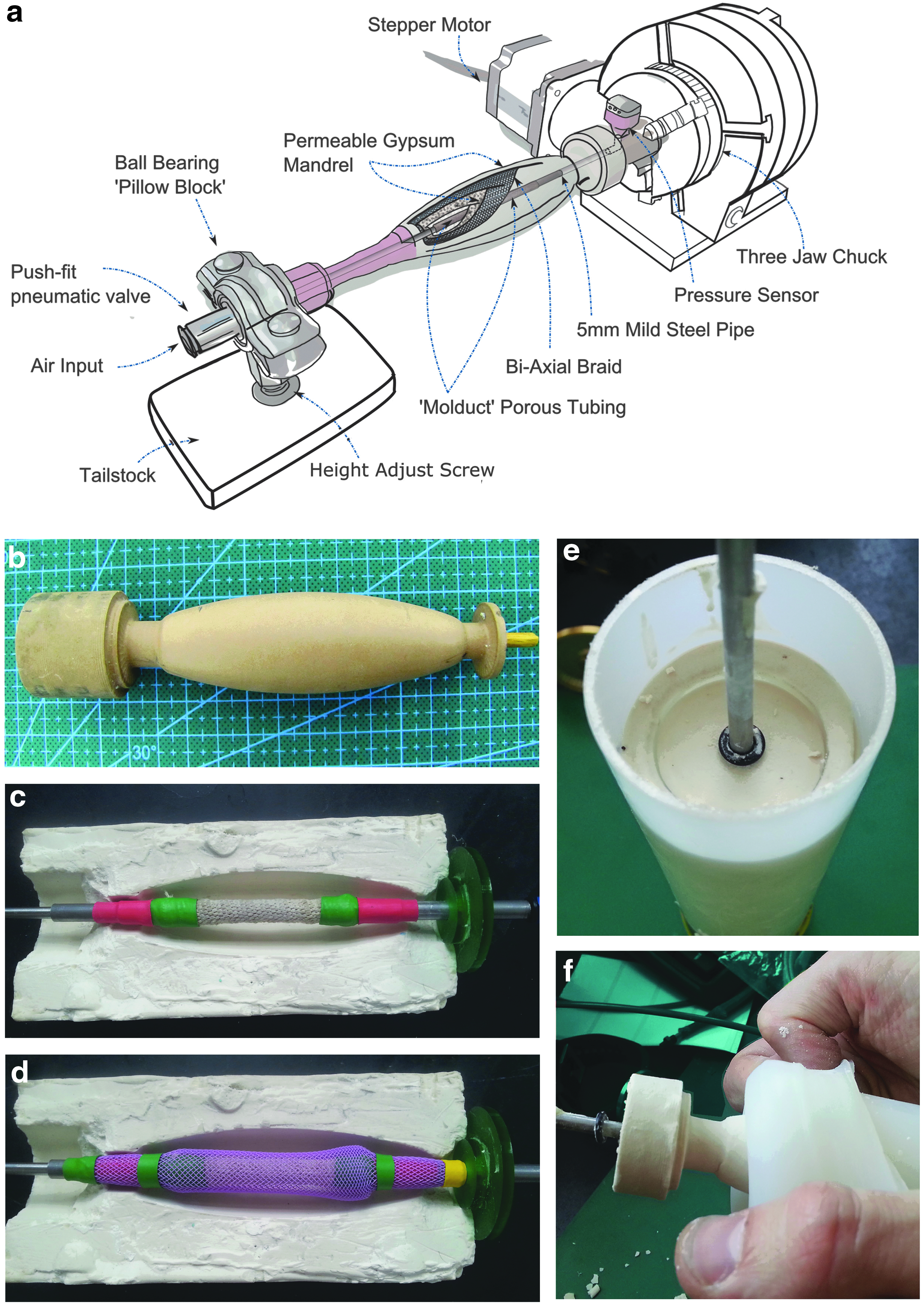
The mandrel itself was built in co-axial layers—shown schematically in Figure 1a. The core was created from 6 mm (outer diameter) 4 mm (inner diameter) mild steel tubing with its mid-section (one third) removed. This gap was bridged by “Molduct” porous tubing (a porous cellulose and cotton woven tube). Cyanoacrylate glue was used to bond the Molduct to the steel and then sealed with a heat-shrink tube, as seen in Figure 1c. An M3 screw thread was tapped into either end of the steel tube, allowing pneumatic fittings to be attached.
The porous Molduct section is the zone from which the inflation pressure emanated. Applied pneumatic pressure created pores in the mandrel that radiated out toward the outer forming surface of the gypsum body. By controlling the length and position of the Molduct, it was possible to specify which area of the mandrel surface became permeable.
To reinforce the gypsum body, a tubular monofilament biaxial braid (Techflex Flexo PPS) was pulled loosely over the core and adhered at the ends, as seen in Figure 1d.
The steel and Molduct core, and braid assembly were inserted into the silicone sleeve mold, and they were kept aligned along the axis by using a custom jig. Figure 1e shows the mold after the gypsum was poured in, and Figure 1f depicts the mandrel removal from the mold after it had set hard.
Gypsum was prepared in excess of what was needed for casting, and a thermometer probe was inserted into the leftover material. The temperature was monitored during the exothermic phase—corresponding to crystallization. At the point where temperature reached a maximum and then began to fall, the gypsum was considered to have hit “initial set,” and all the water required for crystallization had been taken up. This does not occur at a definite temperature or time—it depends on ambient temperature and that of the water used. In these experiments, the water was chilled to 6°C before use, to minimize variation. When Alpha gypsum was tested, it had a pour time between 6 and 8 min and an initial set time between 30 and 35 min. Beta gypsum was considerably slower to crystallize, remaining pourable for up to 15 min, and setting at ∼45 min.
At the point of full crystallization, pressurized air was driven into the core of the plaster body to remove any held water not required for the reaction; this is termed the “purge cycle” and is depicted in Figure 2a. Initial purge pressure was kept low, beginning at 70 kPa, and then slowly increased by 35 kPa every 5 min over the course of an hour to 480 kPa.

A complete mandrel including a core pressure sensor at the proximal (motor) end, and pneumatic fitting and centering bearing at the distal end is shown in Figure 2b.
Figure 2c and d compares what is considered a poor and good resulting mandrel surface (respectively) after the purge cycle.
When the purge cycle was complete, the resulting final body was a highly and persistently permeable mandrel with pores of ∼1 μm. 19 Figure 2e shows the mandrel submerged in water with compressed air driven through the surface.
Testing of mandrel permeability
A number of methods were investigated to ascertain whether a reduction in pressure differential between core and surface was readily attainable. This was to allow maximum control over the inflation. Two different types of gypsum were tested—a high-density plaster with high Alpha-hemihydrate content (LaFarge Presta Form) and a low-density, predominantly Beta-hemihydrate plaster (Saint Gobain Pottery Plaster). The Presta Form has a Brinell Hardness of 150 N/mm2. When the recommended water to plaster ratio (WPR) of 37% by weight was used, the resulting body had a (pre-treated) porosity of 15%. 20 The Pottery Plaster had a recommended WPR of 68%, resulting in a Brinell hardness of 20 N/mm2 and a porosity of 44%. 21 These two forms of gypsum are at either end of the available spectrum in terms of hardness and porosity. It is worth noting that the porosity quoted does not guarantee true permeability.
In addition to testing the two materials in their recommended form, variations were made in the WPR, together with the initial and incremental pressures used during the purge cycle to test whether higher initial water content would result in a more porous final body. This assumption came from the observation that the gypsum body does not shrink during crystallization when a high WPR is used, therefore the crystal structure must be less dense. In addition, it was supposed that a faster purge cycle may remove more held water before final set, thus increasing final permeability.
A test was performed to ascertain whether the removal of trapped air bubbles would result in a better surface, without negatively affecting permeability. Here, fresh mixed gypsum was poured into the mold, and then vacuum degassed (Christ Alpha 1–2 LDplus Freeze Dryer). Pressure was reduced to 100 mbar at room temperature and then released.
A test setup was constructed to measure the pressure drop between the core and surface of the plaster with various mandrels. The setup (Fig. 3) consisted of a 350 mL high-density polyethylene tubular container, with a pressure sensor (Honeywell 40pc100g) fitted and sealed at one end to measure the pressure on the outside of the mandrel. The mandrel to be tested was inserted into the tube, and it was sealed at the other end by using a silicone stopper with two 4-mm pneumatic pipes through it. Two pneumatic pipes were connected to either end of the mandrel. One of these pipes was connected to a second pressure sensor, which was used to measure the pressure in the core of the mandrel. The other was connected to a three-by-two-way valve through which pressurized air could be controlled (and vented). Air pressure was digitally controlled by using a Festo VPPE digital air pressure controller.
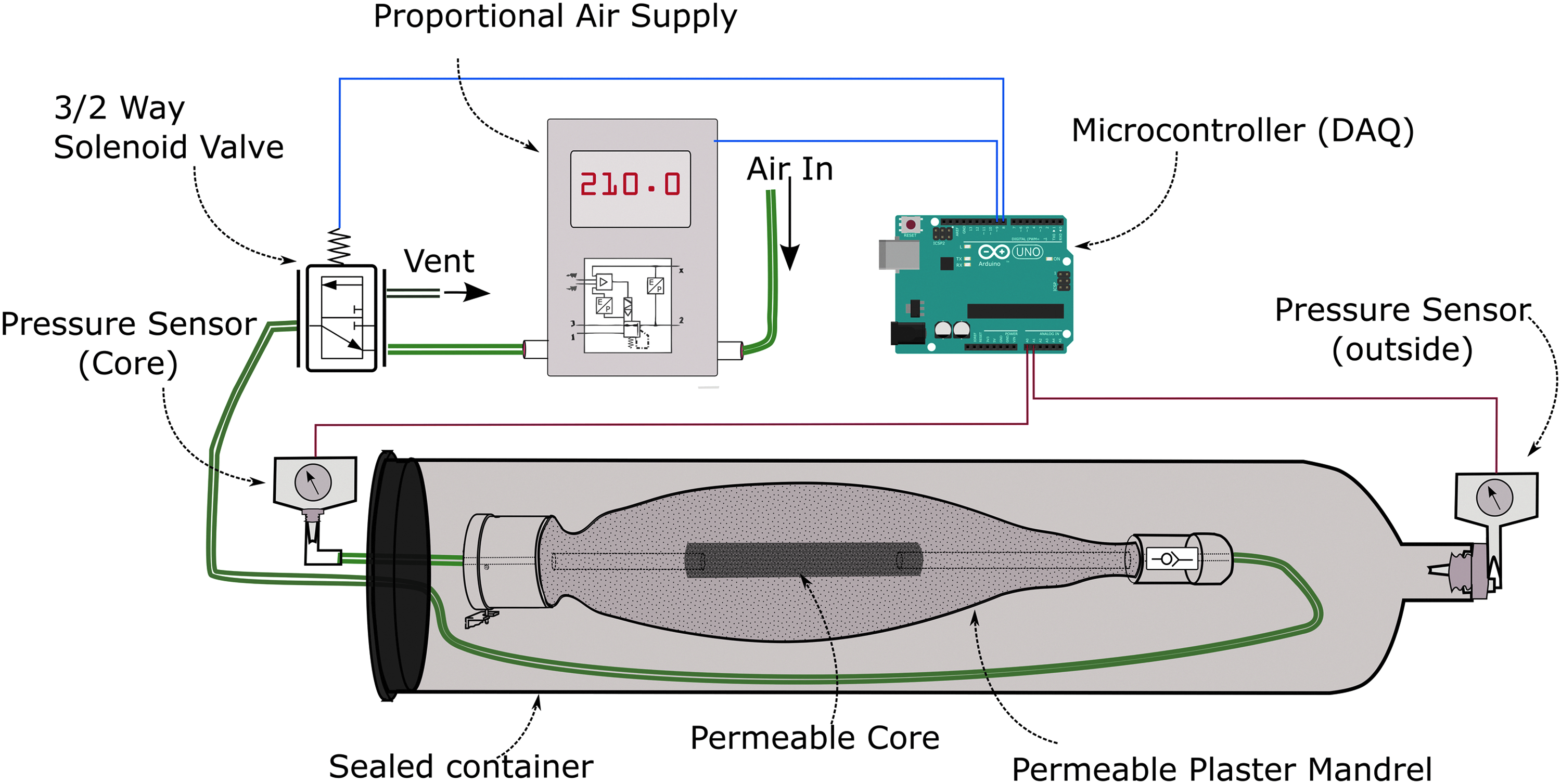
Test setup to evaluate mandrel permeability.
Spray deposition on mandrel
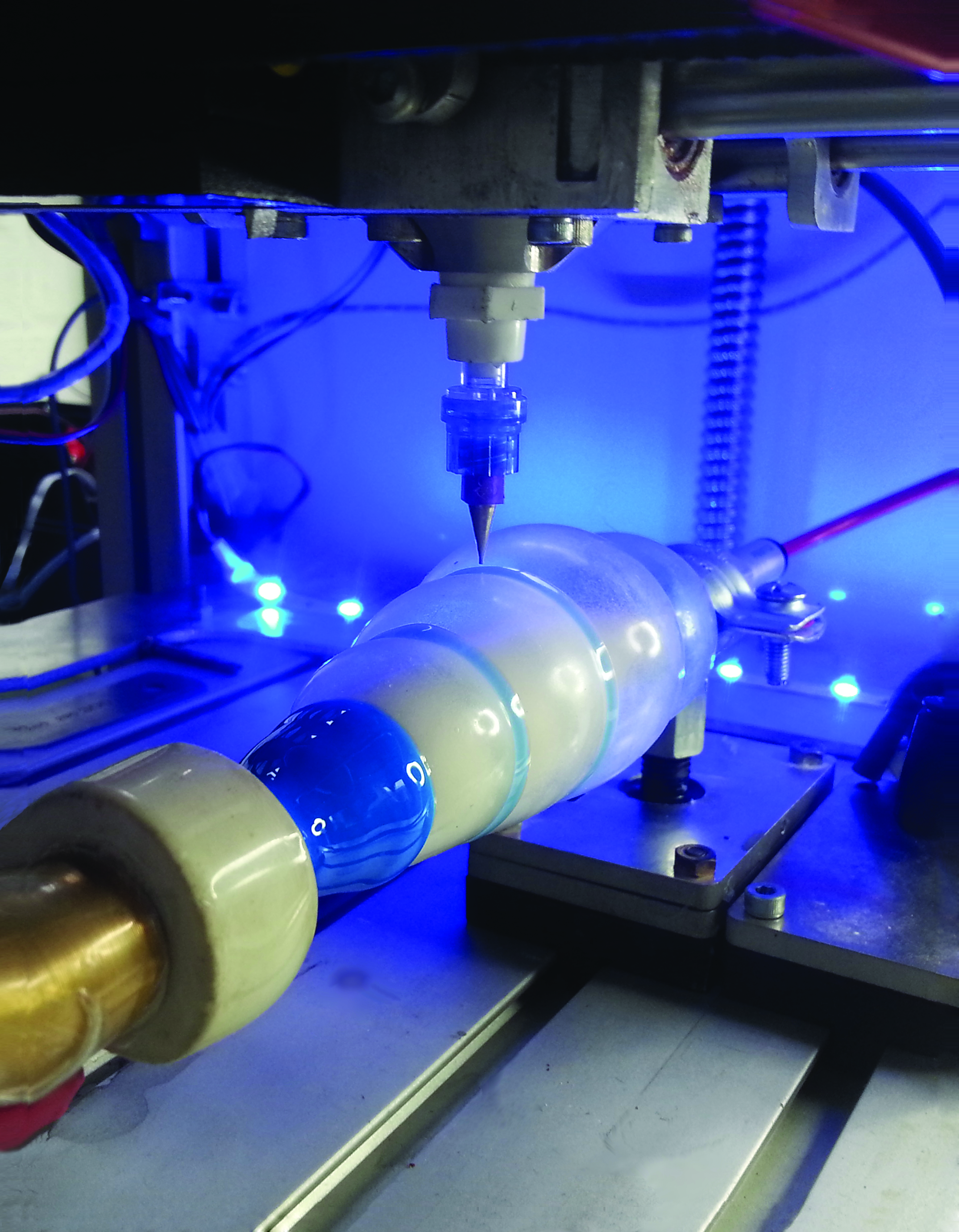
Spray coating the mandrel was accomplished by using an atomizing nozzle mounted on the 3D printer (Fig. 4). The printer gantry (BFB-3000) was modified by removing the hot plastic extrusion nozzle and replacing it with a spray valve (Techcon TS-5540) along with removing the proprietary control circuitry and replacing it with an open-source RAMPS system. The schematic in Figure 4a shows the direction of the X, Y, Z, and θ axes; a photograph of the spray system is shown in Figure 4b; and the curing of a membrane using infra-red is shown in Figure 4c.

This spray system can be considered as analogous to an additive lathe. The major operating difference with this machine when compared with a subtractive one is the inability to dwell in one position (with the spray valve open) without negatively affecting the surface thickness homogeneity or introducing subsurface air bubbles. Moving the spray head too slowly along the mandrel or with too high a material output will also result in an uneven surface deposition.
The parameters: Material and atomizing pressure, along with needle valve open/close operations were controllable by individual pressure regulators with solenoids attached. The permeable mandrel assembly illustrated in Figure 1a was fixed at one side of the printer, lengthways to the spray valve.
The method used to ensure even coverage of material was a “constant angular velocity” (CAV) approach. This is where the mandrel was rotated at a CAV ω, whereas the spray head moved at a variable speed Vxy while at a constant distance from the substrate. To achieve CAV, the spray carriage was moved at a speed that was inversely proportional to the mandrel radius r at that point. The net result is that the spray head spends the same amount of time over any particular area of the mandrel surface, regardless of the radius at that particular cross-section.
Testing of solvents and spray valve parameters
The spray valve used—Techcon TS-5540 with 1.17 mm nozzle—had a quoted maximum material viscosity of 10,000 mPa·s. The material used was Smooth-On Ecoflex 00-30, with a mixed viscosity of 6,000 mPa·s. When sprayed in undiluted form, the elastomer did not atomize well. It required a very high atomizing pressure, and it formed large droplets that agglomerated on the substrate. The material eventually slumped and merged, but this happened in an extremely random and uneven manner. It was felt that a solvent was required to achieve an even coating.
Lotoxane (Arrow Chemicals), an aliphatic hydrocarbon solvent, was mixed with the silicone at 15% by weight. This reduced the silicone viscosity to 1800 mPa·s. Even at this reduced viscosity, a reasonably high atomizing and material pressure was required to create a consistent spray pattern (these pressures were kept equal). Through initial experiments, pressures >200 kPa were found to be preferable for creating a homogeneous layer thickness without the material “spitting” from the valve. At such pressures, it was necessary to keep the deposition nozzle at a distance of at least 80 mm from the substrate. Anything closer tended to leave a central furrow in the deposited line.
After initial test observations, parameters were refined and an experiment (n = 36) was conducted to determine the effects of spray head speed along the linear axis, constant rotation speed of the mandrel, material and atomizing pressure, distance of the mandrel from the substrate, and the number of spray passes. The latter was a test to determine whether the application of a second layer before the first had fully vulcanized would improve layer consistency. Some non-sensible combinations such as high material pressure at close distance were discounted, as was a low rotation speed with a fast, linear print carriage speed (which would result in a non-overlapping helix of material being deposited). A subset of the factor combinations was chosen where some of the combinations were replicated, thus allowing errors to be determined after statistical analysis by multiple regression. Table 1 shows the upper, middle, and lower values of the test parameters. After each sprayed layer was cross-linked, the top surface was dusted with graphite, to help delineate the layers while measuring.
RPM, revolutions per minute.
When the experimental sprayed silicone films had hardened, they were removed from their mandrel and sectioned to allow the thickness of the layers to be measured. Sections were cut at intervals of 10 mm along the length of the “balloon.” To ensure all cuts were made with a precise cross-section every time, a sacrificial mandrel was put in place of the gypsum one. In this case, a root vegetable (carrot) was pared to resemble the original mandrel shape and then inserted into the silicone films. Cutting was performed in a single cut with a chef's cleaver.
The thickness of every layer on each cross-section was measured three times, each 120° apart by using the measurement microscope in a FujiFilm Dimatix DMP2600.
Results and Discussion
The mandrel
Tests conducted with the two forms of plaster at different WPR and purge pressures were designed to measure air percolation rate through the mandrel body. This was performed by recording the time taken for pressure to equalize between the inside (core) and the outside (surface) of the mandrel—as per Figure 3. Variables tested are shown in Table 2.
WPR, water to plaster ratio.
The experiment involved recording the core and the surface pressures of the mandrel every 100 ms for a total of 50 s while the core was exposed to an initial pressure of 210 kPa. The core pressure was then vented, allowing the surface pressure to percolate back through the mandrel.
The core and surface pressures are plotted against time (Fig. 5) by using dashed and dotted lines, respectively. The differential pressure across the sensors is plotted by using solid lines.
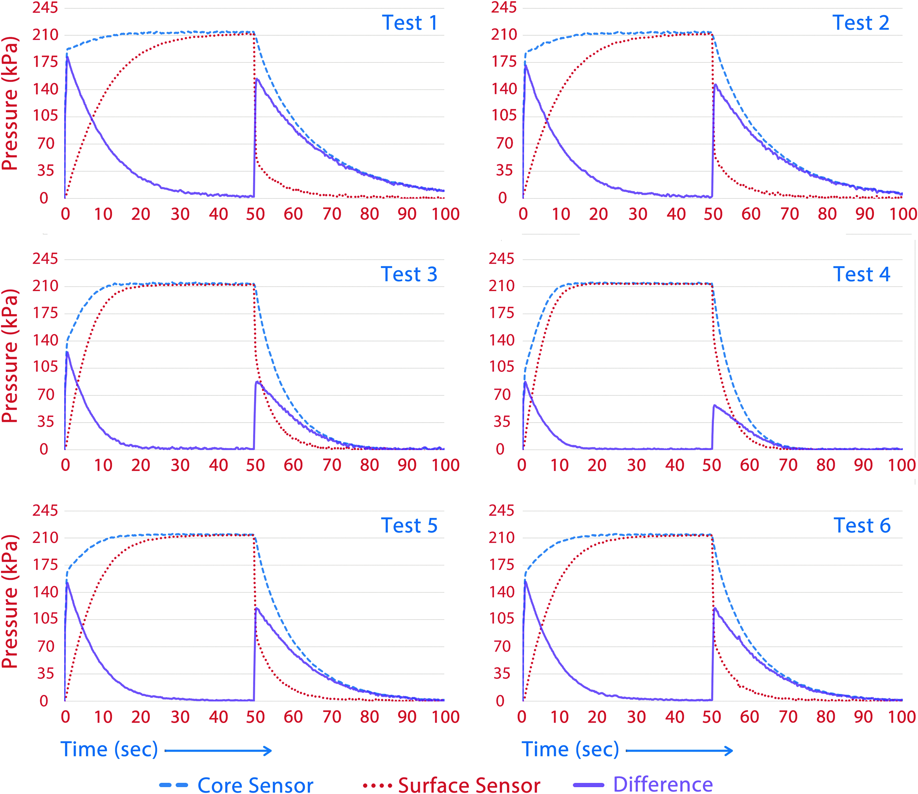
Pressure differences between core and surface of mandrels of varying types. Dashed line represents sensor readings from core of mandrel, dotted line represents the surface, and solid line shows the differential pressure.
The difference in pressure between the core and surface measurements—ΔP—was statistically analyzed; the summary statistics are shown in Table 3. These consist of the mean ΔP, standard deviation of ΔP, median of ΔP and Q3 ΔP (i.e., the pressure difference above which one quarter of the readings lay) and Max ΔP, and the maximum pressure difference between the core and the outside. Measurements: ΔP < 7 kPa (↑) (s) and ΔP < 7 kPa (↓) (s) represent the time in seconds for the pressure difference to drop to 7 kPa when the pressure is increasing and decreasing, respectively.
SD, standard deviation.
Experimentally, it was found when casting with LaFarge Form plaster, that a very high WPR (>50%) results initially in a smooth glass-like surface. Ultimately, it was not a practicable way to achieve a quality casting. The surface degraded significantly at the higher pressures used near the end of the purge cycle, similar to that shown in Figure 2c.
The same material at WPR of 45% gave a good balance of reduced viscosity for pouring without reducing the structural integrity required for a successful purge cycle. Due to the low WPR required—and therefore short working time—it was not possible to pre-process the slurry by using methods such as vacuum degassing. Vibration during casting helped the migration of any trapped air up to the surface, resulting in a smooth final surface (Fig. 2b, d).
When the mandrel is composed of “Prestia Potters” beta plaster, it can be seen in Table 3 that the pressure differential between the outer and inner surface is significantly less than with “Form” alpha plaster. The time taken for the two surfaces to equalize is also much shorter—as little as half the time. This increase in responsiveness comes at the cost of surface quality. The high pressure required at the end of the purge cycle tends to erode the surface. Using fine (1800 grade) sandpaper on the surface (during, but near the end of the purge) will somewhat mitigate this, but doing so is only possible when the mandrel is a simple shape, as in this case.
Vacuum degassing does help remove trapped air bubbles at the interface with the mold, but not any more successfully than using vibration. A degas step reduces permeability also.
Spray test
Regression analysis (Table 4) was undertaken to relate the mean thickness of each layer to head speed, rotation speed, pressure, distance of the head from the mandrel surface, and number of passes of the spray jet. These were assumed to be the main factors that influenced the spraying of medium viscosity elastomers.
ANOVA, analysis of variance; df, degrees of freedom; SS, sum of squares; MS, mean square.
The coefficient of determination (R2) of 0.68 shows that the regression line fit the measured data points very well. This can be seen by examining a scatter plot of measured versus predicted thicknesses (Fig. 6a). The statistical significance of the F ratio (regression mean square/error mean square) is very high—the probability ≈2 × 10⁻⁶ demonstrates that the results could not reasonably have been arrived at by chance.

Regression plots.
Head speed was found to be the dominant factor influencing the evenness of coating at differing mandrel radii; thus, faster head speed resulted in a smaller variability in thickness (Fig. 6c).
An examination of the calculated probability values (Table 4) shows that the variable “number of passes” was the most significant factor in determining the thickness of the layer. This is not surprising, as a second pass will double the deposition time for any single area. Head speed and pressure are of lesser significance, but still important factors. All three have p-values of <0.05, thus allowing the null hypothesis to be rejected for these variables. Single variable plots for number of passes and head speed are presented in Figure 6b and c. Pressure is not shown as a single plot as alone its effect was not significant; however, the effect of pressure may have been confounded with other factors arising from an incomplete dataset where all combinations of variables were not included.
Rotational speed appears not to influence the layer thickness at the specific angular velocities tested. This was shown by a 49% probability coefficient.
Figure 7d and e are graphs that show the mean sampled layer thickness of a sprayed membrane; each thickness is an average of fifteen measurements. These were measured at five different cross-sections on the tube spaced 10 mm apart. Figure 7d shows the most consistent two layers for a single pass spray and two for a double pass, the parameters of which are shown in Table 5.
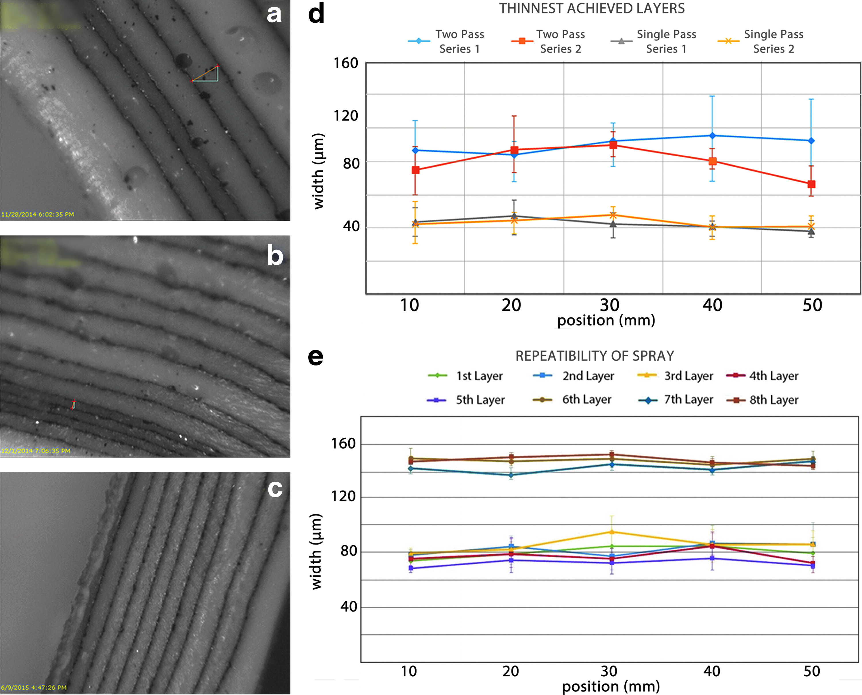
An examination of the curves shows that the best layers created with two passes display large variation in thickness and have large error bars. Not shown in the graph is the large number of trapped air bubbles in the layers; these are clearly visible in Figure 7a and b. In contrast, the best two single-pass membranes are more satisfactory in their uniformity and standard error.
Figure 7c shows repeatability in the thickness of layers when holding the spray parameters constant and applying layers on top of each other. Layers 6 − 8 in this series represent a two-pass spray, but in this case the first layer is vulcanized before the second is applied. Using this technique, the standard error and uniformity are improved, without introducing air bubbles.
Inflation of membranes and simple deposition printing
Balloons were prepared by depositing eight single-pass layers at the optimal parameters—as per Table 5 and Figure 8c. This resulted in a series of balloons with an average wall thickness of 560 μm (uninflated).
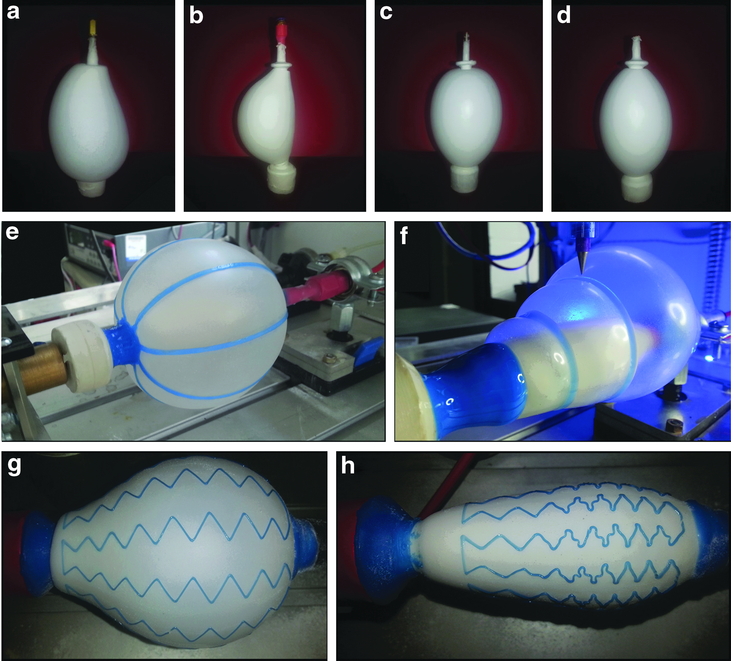
The final inflated shape of four different balloons is shown in Figure 8a–d. The first two, Figure 8a and b, were sprayed onto mandrels composed of the softer Beta plaster. They show an obvious lack of axial symmetry, which resulted from the adherence of the silicone membranes to the mandrel during inflation due to surface roughness. The second pair, Figure 8c and d, was much more satisfactory—due to the use of smoother surface mandrels made of alpha gypsum. It is significant that non-symmetric balloons will display a variation in stress softening across the surface of the membrane, and will repeatedly inflate in this non-symmetrical manner. It is noticeable that although the inflated membranes in Figure 8c and d are relatively symmetrical axially, they display a different overall profile shape along the axis. This is despite all spray parameters being identical for both pieces.
Figure 8e and f show that balloons inflated after Shore 30A hardness thixotropic silicone (Smooth-On Mould-Max 30, with 3% Smooth-On ThiVex additive) had been 3D printed on them—one longitudinally and one co-axially. This demonstrates an ability to vary the final inflated shape without changing the mandrel design.
Figure 8e and f, respectively, show balloons with longitudinal and co-axial lines printed on them before inflation. Figure 8g shows an inflated balloon with a zigzag pattern printed over its stretched surface and Figure 8h shows the same balloon deflated, illustrating variation of strain across the surface of the membrane. The methods used to 3D scan the dimensions of the balloon substrate and then calculate constant line thickness toolpaths over the curve-linear surface are discussed in Part II of this series.
Conclusions
The mandrel
Pneumatically treated gypsum provides a low-cost and flexible method with which to create permeable mandrels. Defects on the mandrel surface are detrimental to the quality of a fabricated balloon. When silicone is sprayed onto the mandrel, it flows into any holes, creating “anchors” that tend to constrain a point of the membrane to the surface during inflation, thus causing non-axial symmetry in the inflated shape.
Using a hard predominantly alpha-gypsum material to fabricate the mandrel results in an overall smoother final surface. However, it also requires a much higher inflation pressure at the mandrel core. The softer and more permeable beta-gypsum-based mandrels need lower pressure but tend to suffer from a shorter useable life. For this reason, alpha-gypsum is preferable in most cases.
Spraying
Spray deposition of multiple silicone membranes layers onto an air-permeable mandrel followed by inflation is a viable way to create balloons with an axially symmetric inflated shape.
With spray deposition of silicone on to complex curved surfaces, variation in deposited membrane thickness is undesirable, so when spraying a high-viscosity material, it is best (1) to use a relatively high atomizing and material pressure of 300 kPa, (2) to keep the spray jet at 120 mm from the substrate, and (3) to traverse the print-head quickly along the axis at 3200 mm/min.
Thickening of the layers sometimes occurs toward the mid-point of the mandrel. This may be a consequence of the greater diameter (Z-width) at the center of the mandrel or of the tendency of the circular spray beam to deposit more material at the center. The slightly thicker layer may confer an advantage during inflation, as the material at the midpoint of the mandrel is subjected to a higher level of strain during inflation, and, thus, becomes thinner.
Spraying a thin layer and then curing, followed by depositing a second layer improves variability significantly. The “double layer” approach does result in membranes with thicker walls, but this is countered by the thinning of the membrane during inflation.
The techniques described in this article have applications in fields such as soft robotics, particularly DEA. Beyond this, the authors see uses within 3D printing of tubular and non-planar objects with removable substrates, uses in stretchable electronics, and four-dimensional printing of objects with multiple varying levels of mechanical strain throughout the object.
Footnotes
Acknowledgment
All experimental work was completed at and funded by Nottingham Trent University, School of Architecture, Design and Built Environment.
Author Disclosure Statement
No competing financial interests exist.