
Abstract
Abstract
As technologies have advanced around medical imaging and additive manufacturing, intersections are producing enabling technologies that augment the medical sciences. Three-dimensional (3D) bioprinting, in particular, is emerging as a promising enabling technology for tissue engineering and regenerative medicine applications. In this study, we developed a workflow to take 3D medical images and utilized them for bone construct design, bioprinting, and in vivo validation. Medical imaging and 3D bioprinting strategy converged to allow the fabrication of a structure with complex shape and inner architecture based on patient anatomy and biomimicry. The workflow demonstrated the power of the technological intersection and the need for further software development to harness and, eventually, explore potential clinical applications. The outcome of this study validated the concept that patient-specific anatomy could be translated to 3D bioprinting strategy through medical imaging and image processing software with strong clinical relevance.
Introduction
T
Medical imaging is here primarily concerned with those modalities that can produce spatially defined data points. 12 The primary modalities are computed tomography (CT) and magnetic resonance imaging (MRI). Other modalities such as positron emitting tomography and 3D ultrasound can be useful. Both CT and MRI data are stored as DICOM (Digital Imaging and Communications in Medicine standard format) files. Based on the technological basis, each imaging modality has strengths and weaknesses. For instance, CT is well suited to resolving bone tissue, while cartilaginous tissues are poorly captured. MRI can resolve soft tissues with fidelity, but struggles with hard tissues such as cortical bone. 13
Computer software is needed to visualize and further utilize DICOM data from these imaging techniques. Viewing software allows users to alter contrast and brightness or other general viewing parameters, but often do not render a 3D image. Instead, 3D data are displayed as three two-dimensional (2D) images along the anatomical planes: sagittal, coronal, and transverse. Other software packages are much more sophisticated allowing 3D rendering, image segmentation, cross-sectional plane rotation, finite element modeling, computer-aided design (CAD), and more. Several software packages can segment a region of interest (ROI), generate a 3D surface model, and export the data as a STereoLithography (STL) file. Most 3D printing systems can directly print an STL model. For bioprinting purposes, an STL file often serves as a necessary input of the fabrication process for an object that mimics the 3D shape/structure of injured, defective, or missing tissues.
Several have reported the use of multiple materials, including various cell types, printed in a single structure.9,14 Others report the conversion of imaging data to printed parts, however, without demonstrating steps needed to combine multiple materials and architectures into one construct of patient-specific shape that is bioprinted, implanted, and evaluated. To accomplish the composition of designs that combine multiple inner architectures and materials in shapes defined by medical images, we used a series of software programs. First, we used Mimics Innovation Suite for its ease of use and readily available tools for image segmentation, anatomy modeling, and design and manipulation capabilities. Second, we used a custom program to slice STL models and generate printing paths for the filament deposition. Third, we used custom software to align printing paths of various regions into a unified construct for bioprinting. For clinical application, further software development is needed to seamlessly produce constructs of necessary complexity in a unified software environment that can withstand the rigors of clinical use.
Here is reported a process to take medical imaging data to a bioprinted construct composed of multiple internal architectures and materials. To investigate the clinical feasibility of this 3D bioprinting strategy, we validate a printed bone construct designed from CT data in a clinically relevant animal model for mandible bone reconstruction. A successful process must be patient specific, able to handle complex shapes, incorporate multiple architectures and materials, as well as hospitable to nondestructive follow-up. Eventually, the process and software tools must be capable of regulatory body approval. The outcome of this study resulted in the identification of a workflow to design, fabricate, and evaluate bioprinted constructs that mimic the anatomical shape of the defective region by using medical imaging as the basis (Fig. 1).
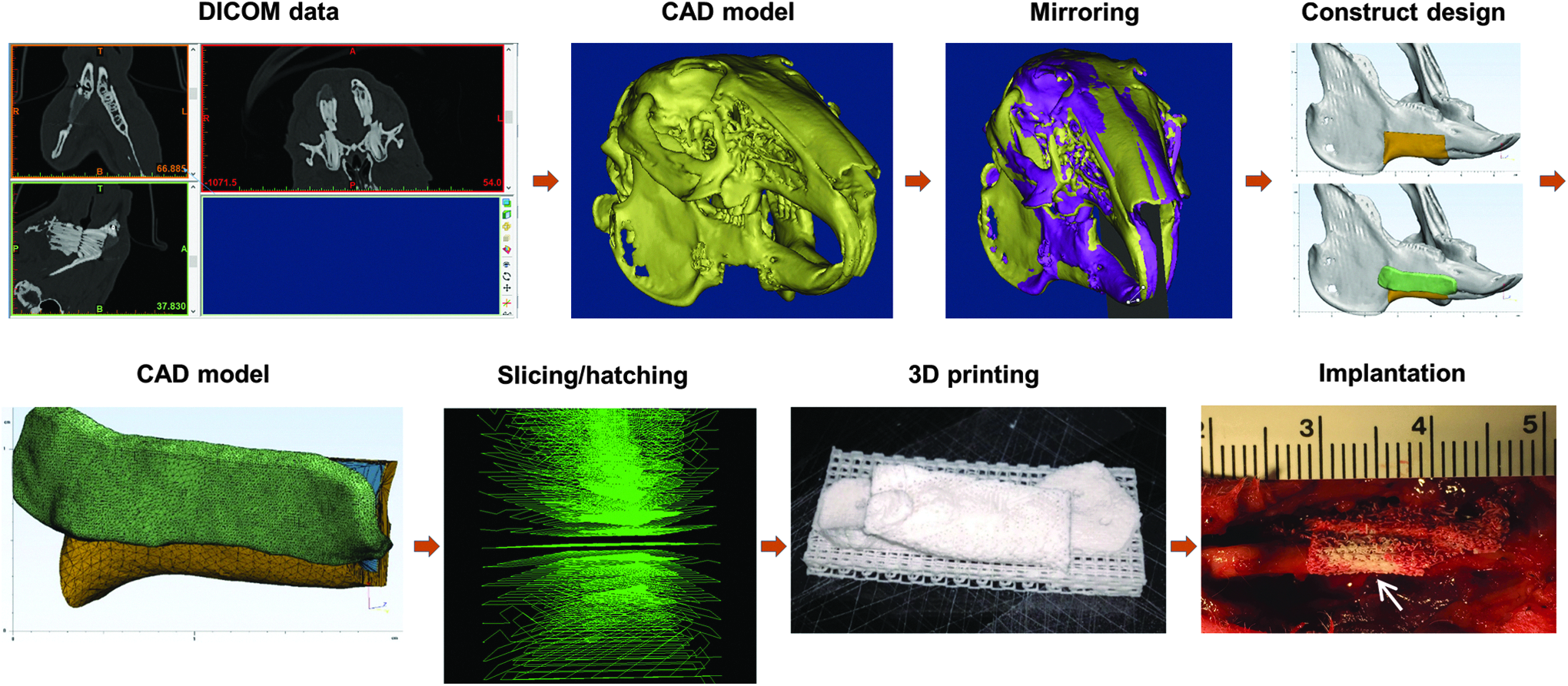
Clinically relevant workflow for 3D bioprinting process from medical imaging data to implantation of a patient-specific tissue construct. 3D, three-dimensional. Color images available online at www.liebertpub.com/3dp
Materials and Methods
Image processing and bone graft design
The full process for segmental mandible bone graft design was performed in the Mimics Innovation Suite (Materialise NV, Leuven, Belgium). This is a software package comprising Mimics and 3-matic. Mimics is a medical imaging analysis environment with tissue segmentation, 3D image rendering, and 3D modeling capabilities. Models can be further utilized in a robust design environment provided by 3-Matic. The bone segmentation tools were used to create subject-specific jaw models. The 3D models were exported to Materialise 3-matic software where they can be used to design directly on the anatomy. The design tools were used for the production of the graft and a fixation plate region to match the contours of the mandible. The graft volume was divided into an external and core mimicking cortical and trabecular stratification.
Bioprinting process
Bioprinting process was conducted on the integrated tissue–organ printing (ITOP) system, as described elsewhere. 9 Briefly, the ITOP system consisted of an X, Y, Z-axis stage/controller and multiple dispensing modules. A three-axis stage system (Aerotech, Inc., Pittsburgh, PA) having 200 × 200 × 100 mm3 travel and controller was used to provide motions for the printing process. The dispensing modules had a precision pneumatic pressure controller (Musashi Engineering, Inc., Tokyo, Japan), a customized metal syringe, and microscale metal nozzle. Customized CAD/computer-aided manufacturing (CAM) process, including slicing, tool path generation, and motion program generation, was used for the printing process. This process is an iteration and reapplication of previously developed works.9,15,16
The bone constructs designed were fabricated from composite material composed of poly(ɛ-caprolactone) (PCL; Polysciences, Inc., Warrington, PA) and β-tricalcium phosphate nanoparticles (TCP; Berkeley Advanced Biomaterials, Berkeley, CA). TCP material was used to improve osteoconductivity.17,18 PCL and TCP were mixed at a ratio of 1:1 by weight in chloroform (Sigma-Aldrich, St. Louis, MO) and then dried under vacuum at 40°C for at least 48 h, followed by cryomill pulverization (Freezer/Mill®; SPEX SamplePrep, Metuchen, NJ). The resulting PCL/TCP powder was loaded into a steel cartridge with affixed 200-μm nozzle (TECDIA, Tokyo, Japan) and placed in the ITOP system. The PCL/TCP composite was heated to 120°C for printing. Stable printing at 1.5 MPa resulted in a nozzle travel speed of 150 mm/min and total fabrication time of 2.5 h.
Mandibular bony defect creation
All animal procedures were performed in accordance with a protocol approved by the Institutional Animal Care and Use Committee (IACUC) at Wake Forest University. A surgical defect is generated in the mandible body of male New Zealand White rabbits (3–4 kg; Charles River Labs., Morrisville, NC). Briefly, the rabbits were anesthetized with ketamine/xylazine (Vedco, Inc., Saint Joseph, MO) and prepared for aseptic surgery. Anesthesia plane was maintained with isoflurane (Halocarbon Products Co., Peachtree Corners, GA). Mandible access was provided by an incision on the ventral side of the right side of the mandible. Soft tissue and periosteum were moved away from the bone in the region of the defect. A Dremel tool with a cutting burr bit (Racine, WI) was used to cut a defect (1.5 cm in length and 1 cm in height) out of the ventral ridge of the mandible body, removing a full-width segment. After the defect creation, CT scan was used to obtain information of bony defect in mandibular body. CT data were collected on a Toshiba Aquilion scanner (Toshiba Medical Systems Corporation, Tokyo, Japan).
Construct implantation
The printed bone constructs were sterilized by ethylene oxide (EO) gas before implantation. For implantation, the rabbits were anesthetized with ketamine/xylazine and maintained with isoflurane. The bony defect region was exposed, and the bone construct was placed in the defect. The construct was held in place by two stainless steel surgical screws through the overlapping printed plate. At the designated time points, animals were humanely euthanized in accordance with the Wake Forest University IACUC-approved protocol.
CT scan and analysis
Slice thickness was set to 0.5 mm. Animal subjects were scanned every 2 weeks postoperatively, with a total of six sets of scan data per animal for longitudinal tracking. The head of the animal was scanned from tip of the nose to base of the skull to include defect region and contralateral region. Postoperatively, the Mimics Innovation Suite was used for analysis of bone reconstruction in the longitudinal CT scans. The first data set, taken before noticeable bone formation occurs, was used for segmentation of the graft architecture. The core architecture was segmented from the external architecture and rendered as a 3D volumetric model. The core volume served as a control volume in which longitudinal bone growth was tracked over time points. The external and core were then aligned together to subsequent external models of later time points, which allowed for the core from the first time point to overlay on subsequent data sets to delineate the control volume within the remaining data sets. Within the control volume, bone threshold values were set to identify new bone growth. Threshold values were set at 675–3171 Hounsfield units (HU) to demarcate bone tissue in postoperative scans. Average radiographic density was calculated for the entire core volume as well as the volume registering within the bone threshold values.
Histological examination
Histological examination was performed on the retrieved bone tissue constructs at 4 and 12 weeks after implantation. The entire bone construct region was removed with surrounding bone and dental tissue. The constructs were fixed in 10% neutral buffered formalin (NBF) for 72 h with a fresh change of NBF after 24 h. The constructs were decalcified for 48 h followed by processing for paraffin infiltration and embedding. Paraffin sections were cut for modified tetrachrome staining. 19 Briefly, 14-m-thick sections were stained with Weigert's hematoxylin, phosphotungstic acid, picro-orange, aniline blue, and a mix of Ponceau 2R and crystal Ponceau. Osteoid and lacunae linings were stained deep blue, mature lamellar bone bright red, woven bone blue with red patches, red blood cells yellow-orange, connective tissue fibers pale blue, and cell nuclei dark brown.
Results
Processing medical images to generate anatomical models
The workflow reported herein started with tissue segmentation in the Materialise Mimics environment after image acquisition (Fig. 2). Tissue-specific pixel values set upper and lower thresholds for automatically generated segmentation masks selecting pixels with gray values within the tissue-specific range. These masks were inspected to ensure coverage of the targeted organ or tissue in 2D and 3D views. Manual selection and deselection tools allowed user corrections to be made, which will be necessary in almost any patient-specific treatment. Once tissues were properly segmented, the masks are used to render 3D models of the tissue or organ. The resulting model will have surface details and potentially internal structural details. Threshold values set to 400–3071 were used to select only tissue with high density or calcium mineral content, which was most likely bone tissue. The mask generated from segmentation caught aberrant tissues or artifacts that were not part of the bony structure. These were easily cleaned from the mask. The mandible region, where the defect ROI resides, was isolated by deselecting regions where upper and lower teeth overlap thereby separating the mandible from the maxilla and skull. After the mandible was separated, internal details representing soft dental tissues, marrow, and foramen were added to the mask to simplify the model and accelerate further processing. The output was a 3D surface model of the mandible with a defect on one side.
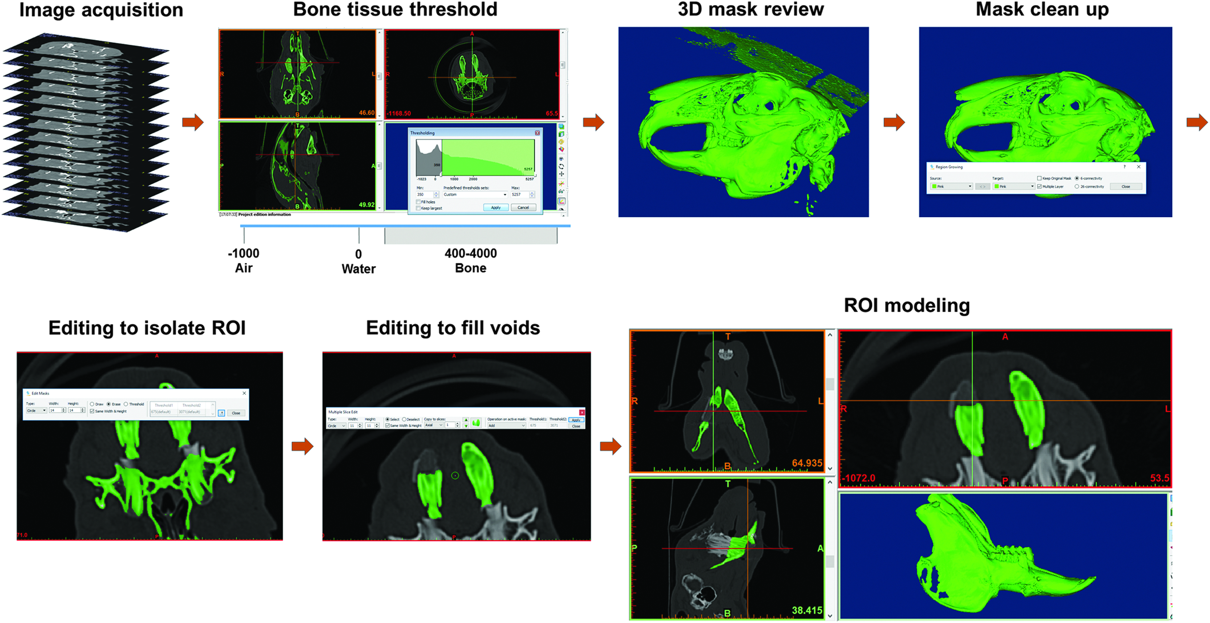
A breakdown of the tissue construct design process starting with CT data acquisition. The data were segmented to isolate bone tissue using HU threshold values from 400 to 3071. Threshold values alone resulted in unwanted data points, which are cleaned with region growing mask editing features. When a defect was present, the area was isolated and modeled in 3D space. Internal voids were filled to simplify further tissue construct design processes. CT, computed tomography; HU, Hounsfield units. Color images available online at www.liebertpub.com/3dp
Tissue construct design for implantation
Next in the workflow, Materialise 3-matic was used to create the regions of the tissue construct that had different architectures and/or materials. For imaging process, the anatomical model needs to be subdivided into volumes requiring different materials or architectures. In cases such as articular cartilage, a certain surface depth may need to be divided from the rest of the model to plan for chondrocyte printing. In other cases, branching tubular designs may need to be separated out for printing vasculature or bronchioles. The final construct may also need additional features to enhance performance or surgeon handling and can be designed at this step in the process. A model can be subdivided by Boolean, cutting, and hollowing operations. After these regions are designed, it is important to ensure that each model is ready to 3D print. The Fix Wizard in the software cleaned the models of any errors in triangulation and ensured that they were watertight, meaning that all surfaces were connected without gaps in the vertices and edges.
In the bone construct, the mandible ROI was divided into regions of the bone construct (Fig. 3). A plane was placed along the midline of the mandible model generated from imaging data. The plane served as a reference about which the mandible can be mirrored to match anatomical shape based on the healthy, contralateral side. The defect region was targeted from the segmented mandible model, and simple geometries (such as cuboidal boxes and planes) were placed as guides for correct graft sizing. These geometric objects were also used at the cutting entities to delineate the volume of interest, and Boolean operations were used to isolate the construct region. The construct region was then subdivided to achieve the design of a nested core and external layer. This bisection was accomplished by hollowing the model such that the external surface was preserved with a user-defined wall thickness leaving an internal cavity. The wall thickness was set to the desired external layer thickness of the construct. The geometric difference between the hollowed and original model resulted in a model used as the core of the construct design. The final region of the construct design was the bone plate. This feature was generated on the mandible model by selecting triangles in the defect region that overlap the implanted construct and surrounding bone determined sufficient for placement of screws, then this surface was separated and modeled with a specified thickness resulting in a part matching the contour of the mandible. These steps allowed for the generation of three models that fit together to satisfy the construct design.

Fitting the defect with the healthy contralateral side was done through mirroring by creating a geometrical plane along the midline and mirroring a copy of the model about the plane. CAD tools were used to hollow the new tissue construct geometry to create the external layer, Boolean subtraction was used to create the core region, base extrusion used to create the bone plate, and Boolean operations were used to generate a support base for the nested structure. CAD, computer-aided design. Color images available online at www.liebertpub.com/3dp
Tissue construct bioprinting
The models were exported from the Materialise 3-matic environment as binary STL files and transferred to custom software to map bioprinting layers (Fig. 4). Custom software was programmed in Visual Studio (Microsoft, Redmond, WA), as described elsewhere, to convert each model from STL models to printable code. 9 Each of the models was imported individually and sliced into layers according to the desired printed layer thickness. Printing paths were then established within each layer by setting several parameters: line pitch, angle of major axis orientation, number of layers before change of orientation, contour scheme, and print speed. These parameters have practical implications on the printed architecture. Line pitch defines the center-to-center distance between printed filaments, which impacts pore size. Angle of orientation and change of orientation affect pore shape, for instance, 90° rotation results in rectangular pores, and the number of layers before rotation affects pore wall height in increments of layer thickness. Three different contour schemes can be selected, which has an impact on the external surface of the printed structure such as printed material all around the contour of each layer, no contour printing leaving an open surface with only filament ends, and contour matching connection between filaments resulting in a contoured surface every other filament. Finally, the speed of the print head can be adjusted for each printing path, impacting the filament thickness as it is printing and the overall job completion time.
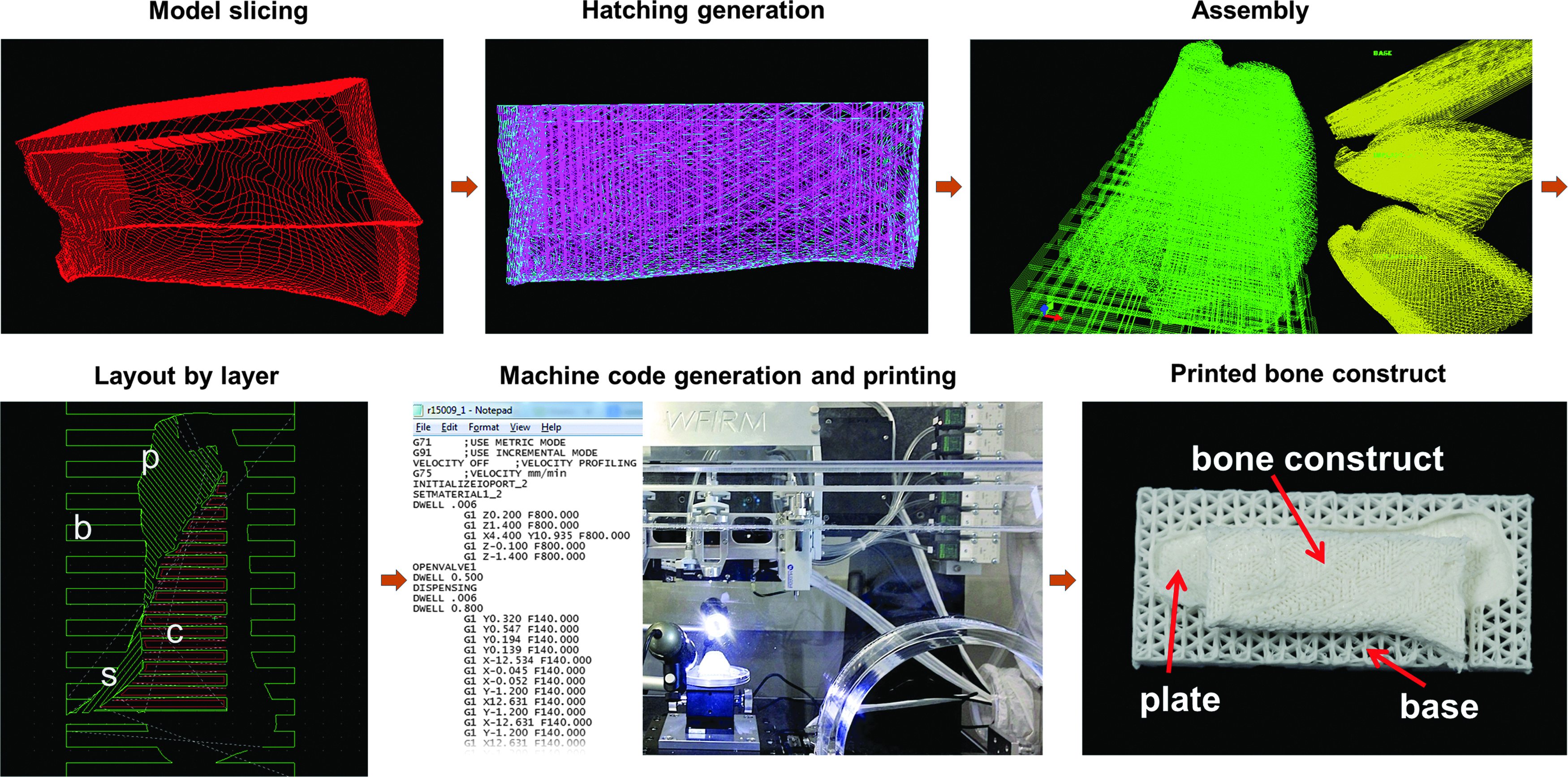
Each model was sliced to the appropriate layer thickness for printing, and print patterns were populated on each layer. The sliced and patterned models were reassembled into the unified construct structure. The layer information along with printing parameters for any materials included in the job was exported as line-by-line code and uploaded to the ITOP system. The construct was then bioprinted in a layer-by-layer manner. p, plate; b, base; c, core; s, shell (external). Color images available online at www.liebertpub.com/3dp
After parameters were selected for each model, printing paths were populated into each layer of each model, and the layers were reviewed for errors. The layered models were assembled into one file within another environment programmed in Visual Studio by aligning the models to re-establish their nested arrangement and exported into a print job file that can be read by the ITOP system. The structure printed in this workflow had distinct architectures for the external layer, core region, bone plate, and base substructure (Fig. 3). The base substructure was torn away from the rest of the graft in preparation for implantation. The length of external layer and core models was 18 mm, which was verified after printing (data not shown), demonstrating maintenance of scale during the design and fabrication steps.
Analysis to measure tissue regeneration
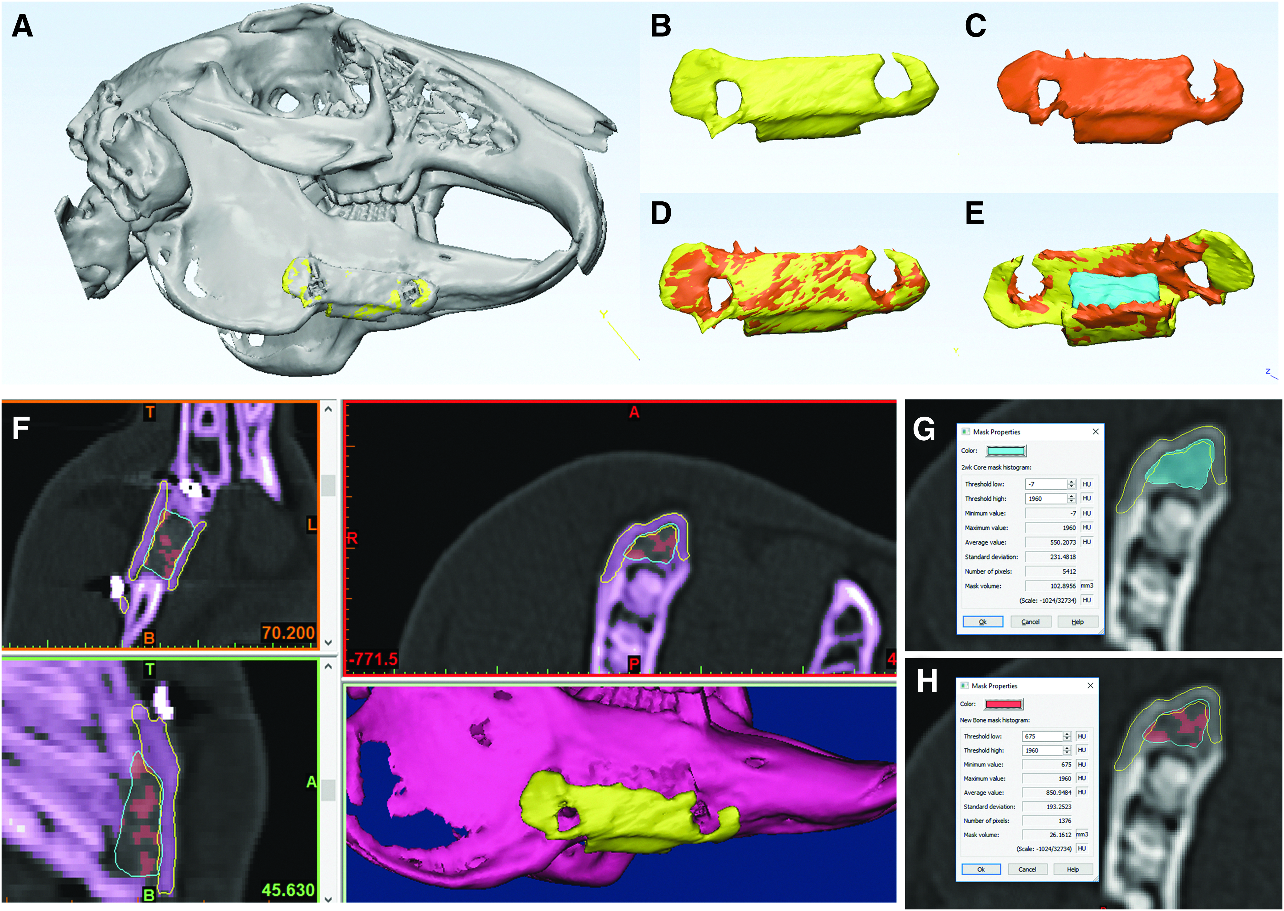
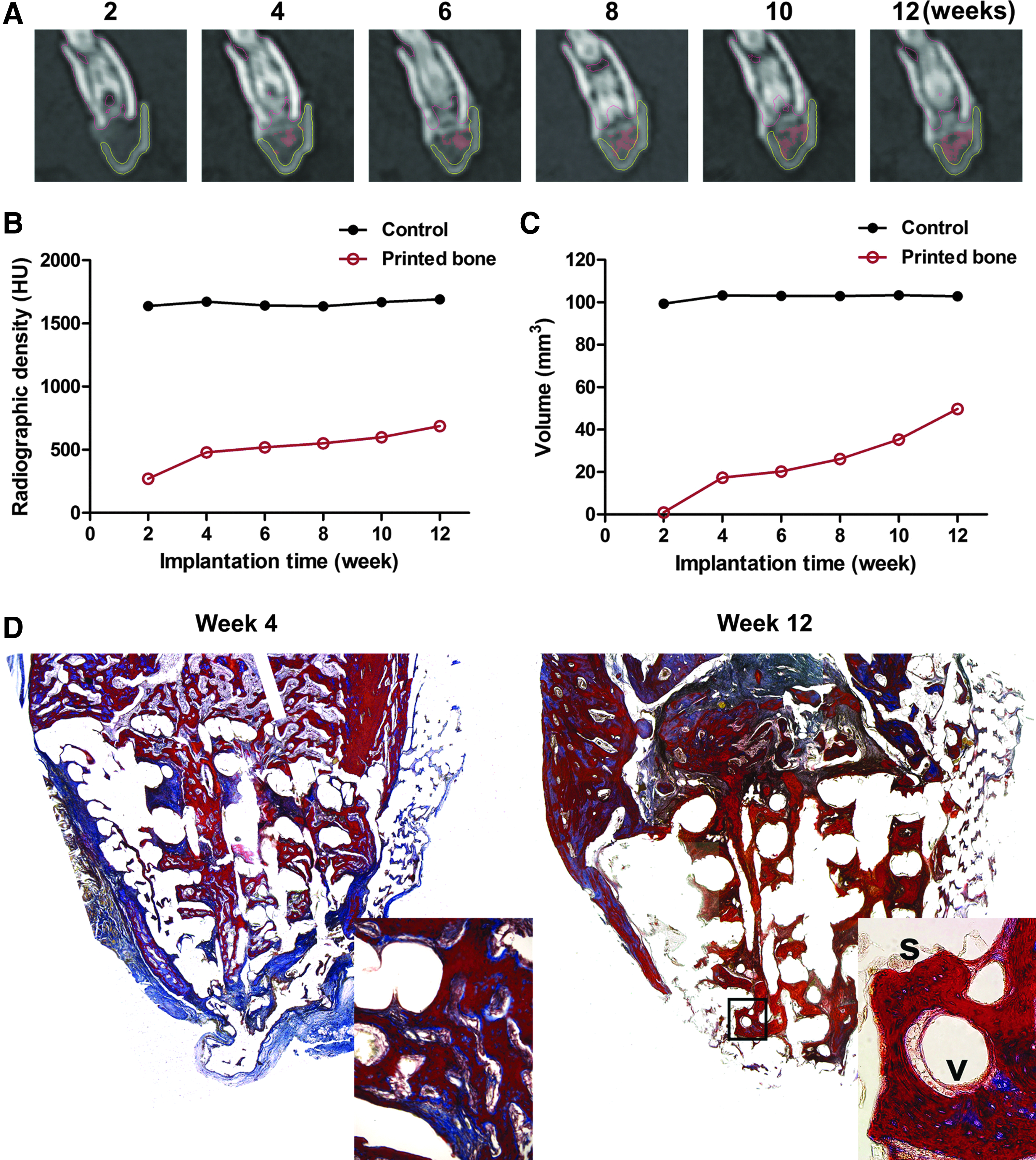
A successful outcome requires clinically relevant follow-up measures that enable physicians to ensure proper treatment and healing after surgery. This workflow included postoperative follow-up via CT with histological confirmation of scan results. The longitudinal data had time points every 2 weeks after surgery. To track the bone growth in the implanted region, initial time point data were segmented into models and compared with the image data from each subsequent postsurgical CT scan. Segmented regions included the external layer, core, plate, and native bone tissue. Registration techniques, including point-to-point registration and global registration, were used to align the initial models to the models segmented from subsequent scans of later time points (Fig. 5A–E). The contours of the registered model were compared to the CT image data in the subsequent scans to add extra assurance that the models were registered well (Fig. 5F). Once the models were registered, the user was able to quantify the new bone growth by isolating the overlap between the core region and native bone region. For instance, the boundaries of the core region at 2 weeks of implantation were overlaid on the native bone tissue volume of the 4-week scans (Fig. 5G). The intersecting areas were used to find the difference in bone tissue volume between the two scans (Fig. 5H). This process was repeated for each postsurgical scan to gather longitudinal data of bone growth quality. With this workflow, we collected several sets of data describing bone growth in the core region, including average radiographic density and volume. The new bone evident in the CT images was highlighted by the red mask and shows increasing occupation of the core region (Fig. 6A). The workflow allowed for quantification of this bone tissue increase, which was reported graphically as core radiographic density (Fig. 6B) and new bone mask volume (Fig. 6C). Both the radiographic density of the entire core region and the volume of tissue registering as new bone increase over time toward the density and volume of the equivalent core volume in the contralateral mandible body.
Models for
Histological examination
Histological outcomes revealed more information regarding the quality of bone growth in the implanted graft. Figure 6D shows modified tetrachrome staining of the 4- and 12-week outcomes with evidence of bone growth into the implanted bone constructs in both instances. Both time points demonstrated clear bone ingrowth into the depths of the core. This result was in alignment with the data collected by CT. The 4-week specimen showed bone organization that was less dense and contained more osteoid, which resolved with a deep blue color. The 12-week specimen had more mature bone with dense organization of collagen shown by the bright red staining. Also note the blue lining of osteocyte lacunae.
Discussion
In this present study, we developed and validated the 3D bioprinting workflow from the medical image to bioprinted constructs. The direction of tissue engineering and regenerative medicine is pointing toward tools such as bioprinting that can pattern various biomaterials and cells into complex patterns in an effort to bioengineer a complex tissue microenvironment in human-scale constructs. To accomplish the bioengineering of a tissue or organ, tools are needed that can produce the complex patterns in the shape of human anatomy. Here we demonstrate that the use of CT imaging and current modeling capabilities allowed for the construct design to match the shape of bone missing in the segmental mandible bone defect. The gold standard autograft must be fashioned from iliac crest or fibula, which rarely matches the original bone shape and causes secondary injury subject to morbidity.20,21 Guiding 3D printing with the spatial data from patient-specific medical imaging can overcome these two major disadvantages.4,5 Advances in biomaterials science and tissue engineering can also be leveraged to design and fabricate a tissue construct that will encourage bone regeneration throughout the entire bony defect region.22,23
Much progress has been made in recent years to make analysis of medical imaging more useful to clinicians and researchers. The ability to segment various tissues from a scan and model them in 3D space has been of great value in identifying and modeling injury, deformity, and malignancy as physicians seek precise treatments for their patients. Medical imaging has transformed many treatments to be more precise and therefore more efficient and effective, notably partial joint replacement and surgical brain treatments. Likewise, we have utilized this modeling capacity to generate anatomically matched tissue constructs with integrated features engineered to benefit surgical implantation and tissue regeneration. Construct design can incorporate engineering considerations such as material composition, printed architecture, pore size, pore shape, and mechanical properties. Other software tools that can be incorporated for medical image segmentation and conversion are available, including open source packages such as 3D Slicer and InVesalius. Several freeware packages are also available for editing and enhancing 3D models derived from anatomical modeling. These software packages include Meshmixer, TinkerCAD, 123D Design, FreeCAD, Blender, and many more. We did not attempt to incorporate alternative applications, but do not foresee problems as long as the packages are appropriately chosen according to the user's experience level and application requirements.
The workflow for this 3D bioprinting strategy has powerful benefits related to the process of subdividing the construct into multiple models independently sliced, patterned, and reassembled. The result is a construct composed of multiple regions that can be fabricated with independent properties, including distinct materials, interleaved materials, distinct pore sizes, and distinct pore shapes. This approach allows for the complex designs that will be needed for tissues with multiple zones with differing properties, for tissue interfaces with multiple cell types, and for organs with different tissues integrated into a single structure. 14 This approach is also important for the ability to interleave two different materials, especially structurally robust materials as a framework for cell-laden materials. 9
This study focused on the bone construct design desired in which the core region represents trabecular bone and the external region represents cortical bone. Reflecting the represented bone types, the core architecture had a highly porous internal architecture with 60% pore space. Contrarily, the external layer had a low porosity of 11%. This bone construct also required methods of fixation to ensure minimal motion after implantation. Fixation can be achieved with plating, steel wire, or other surgical hardware; however, this bone construct was designed to incorporate fixation. In this workflow, the bone plate was designed into the construct with the purpose of fixation by placement of stainless steel screws through the plate and into the bone without the need for plates or wires. This strongly suggests that any design concepts can be reflected in a printed construct through this 3D printing strategy.
In some cases, a contralateral region will not be available for mirroring, such as midline injuries or bilateral damage. This workflow can readily be altered to utilize scans from patients of similar anatomical measurements to get a good fit and similar result. Materialise has the ability to use Anatomical Data Mining (ADaM) to create anatomical models based on population averages, incorporating a variety of demographic details. Models such as these could also be used and scaled to the patient's anatomy to generate appropriately shaped structures to aid in tissue regeneration that will also promote aesthetically optimal results.
The compatibility of the workflow with the ITOP system has far reaching implication for future research and potential clinical tissue-engineered solutions. The ITOP system allows for the printing of multiple materials in a single structure, including multiple cells and polymeric biomaterials.9,14 Therefore, complex structures of anatomical shape composed of various biomaterials and cell types aimed at regenerating composite tissues is a viable goal. For instance, a traumatic craniofacial injury involving bone and adjacent muscle may be targeted for treatment planning and construct fabrication utilizing this workflow and bioprinting.
To date, there are still deficiencies in software solutions available specifically for bioprinting. Specifically, there is a need to develop hatching strategies that are amenable to bioprinting tissues rather than rapid prototyping polymers in traditional 3D printing. Currently, the underlying hatching patterns of a 3D model, which control how a bioprinter produces the physical part, are often programmed by researchers using custom code. The nature of custom solutions makes it difficult to standardize and disseminate acquired knowledge in bioprinting.
As the complexity of bioprinting rises from single tissues into complex tissues or organs, it can be onerous to produce the desired scheme for printing these complex constructs with multiple materials and architectures. Although this initial study only used models of the bone, future studies could include more tissue types. Thus, there is a need to have a software solution that can handle complex tissue architectures, such as vasculature and functional inner structures, and produce bioprinting paths that will interweave multiple tissues correctly.
Conclusions
The workflows presented here demonstrated the potential for utilization of 3D bioprinting strategy in conjunction with medical imaging and modern software tools. The analysis workflow was applied by analyzing longitudinal CT scan data sets from a mandibular defect treatment in rabbits. The image segmentation and registration techniques of the analysis allowed for accurate tracking of bone growth within the implanted bone constructs by quantifying average radiographic density of the implanted region and volume of new bone tissue regeneration. The ingrowth of bone was validated by histological examination. The alignment of CT and histologic data demonstrated the clinical relevancy of this workflow to both design and track the bioprinted constructs. Based on this methodology, it is feasible to bioprint a clinically relevant tissue construct and track its performance in situ. Moreover, the precision and reproducibility of bioprinting allow for control over fabrication processes necessary for appropriate regulatory oversight.
Footnotes
Acknowledgments
We thank Dr. Han Su Kim, Dr. Ickhee Kim, and Dr. Jae-Gu Cho for their surgical expertise in performing implantations and Adam Wilson, Renae Hall, Cynthia Miller, Melissa Ayers, Anna Young, and the Animal Resources Program (ARP) staff of Wake Forest Baptist Medical Center for animal assistance and care. We also thank Debra Fuller for conducting the CT scans. This study was supported by the Armed Forces Institute of Regenerative Medicine (X81XWH-08-2-0032).
Author Disclosure Statement
The authors have no conflicts of interest to disclose.