
Abstract
Abstract
This study is on developing a simple motionless printing in which polyacrylonitrile and N,N-dimethylformamide solution is electrically driven from a fixed nozzle head in a coagulation medium of chloroform and mineral oil. The effect of liquid medium on the bending instability of the jet is studied using the discretized model and experiments. Furthermore, for motionless printing, the inhibited bending motion of the jet is used to control the deposition of the jet to form a square pattern on the collector. The resulting fiber collection pattern obtained from the experiments is favorably compared with the simulation results. In addition, the effects of the switching time and distance between the collector plates on the accuracy of the square and circle three-dimensional patterns are studied from the simulation.
Introduction
T
Electrically driven fibers have been of interest in the area of two-dimensional and three-dimensional (3D) printing to fabricate ordered fiber mats.33–40 Melt electrospinning has been widely used for this purpose.36–39 However, there are several shortcomings in this process 36 : (1) only limited materials can be melt spun, (2) mechanical motion of the nozzle head and/or collector results in long print time and poor resolution, and (3) the electrostatic forces between collected fibers restrict the controlled deposition of the 3D constructs to 1 mm. In contrast, in immersed electrospinning, wherein the electrically driven jet ejected into a liquid medium can be a better alternative because (1) it potentially increases the collection depth profile due to reduced charge build-up on the jet41–43 and (2) the drag force due to the surrounding liquid retards the motion of the jet, which makes it possible to form a controlled pattern on the collector without the movement of nozzle head and collector.
In this work, the bending instability of the fiber is studied as it affects the fiber trajectory during its deposition on the collector. The complexity of solving the equations for the rapid chaotic motion of the jet limited the theoretical study on the bending instability. Therefore, the discretized model with bead-spring approach19,24–32 has been used in this study to model the bending motion of the fiber in the immersed electrospinning setup. This model simplifies the equations of motion and makes it easy to solve and apply the stability analysis. In this study, the bead-spring model is modified to incorporate the drag and dielectric effects. The reduced chaotic motion of the jet in this setup makes it easier to take visualization images at a low frame rate and high exposure time, because of which the lighting and the depth of field are not compensated. This can then be used to test the validity of the discretized model. Finally, for the 3D printing application, the bead-spring model is employed to form a pattern on the collector. This is achieved by applying a temporal boundary condition on the voltage on the collector, and the simulation results are then compared with the experiments. With suppressed bending motion and guided deposition of the jet, the print resolution is limited only by the material delivery system.
Immersion Electrospinning Experiment
Experimental fluids
The spinning solution is 10.5 wt% of polyacrylonitrile (PAN) in 99.8% anhydrous N,N-dimethylformamide (DMF). PAN (150,000 g/mol) and DMF are purchased from Sigma-Aldrich. This solution is spun into a coagulation medium of 2:1 chloroform and mineral oil mixture. Mineral oil is purchased from Fischer Scientific and chloroform is from Macron Fine Chemicals. The material properties of the spinning solution (PAN and DMF solution) and coagulation medium (mineral oil and chloroform) are presented in Table 1. The dielectric constant and the conductivity of the PAN and DMF solution, and viscosity of DMF are taken from the literature.44–46 The viscosity of the coagulation medium is obtained from the Gambill method for the viscosity of liquid mixtures. 47 The rest of the properties are taken from our previous work. 42
DMF, N,N-dimethylformamide; PAN, polyacrylonitrile.
Experimental setup
The experimental setup for immersed electrospinning is illustrated in Figure 1. The coagulation bath contains a mixture of liquid chloroform and mineral oil. The PAN–DMF solution is pumped out of a 25-gauge needle at a flow rate of 0.5 mL/h by using a programmable PHD ultra syringe pump (Harvard Apparatus). The voltage difference in the spinning gap is obtained by connecting the needle to the ground and applying the desired voltage to the collector with a Gamma High Voltage Research voltmeter. The experiments are conducted at 5, 7, and 10 kV voltage differences, and the spinning distance is ∼9.5 cm.
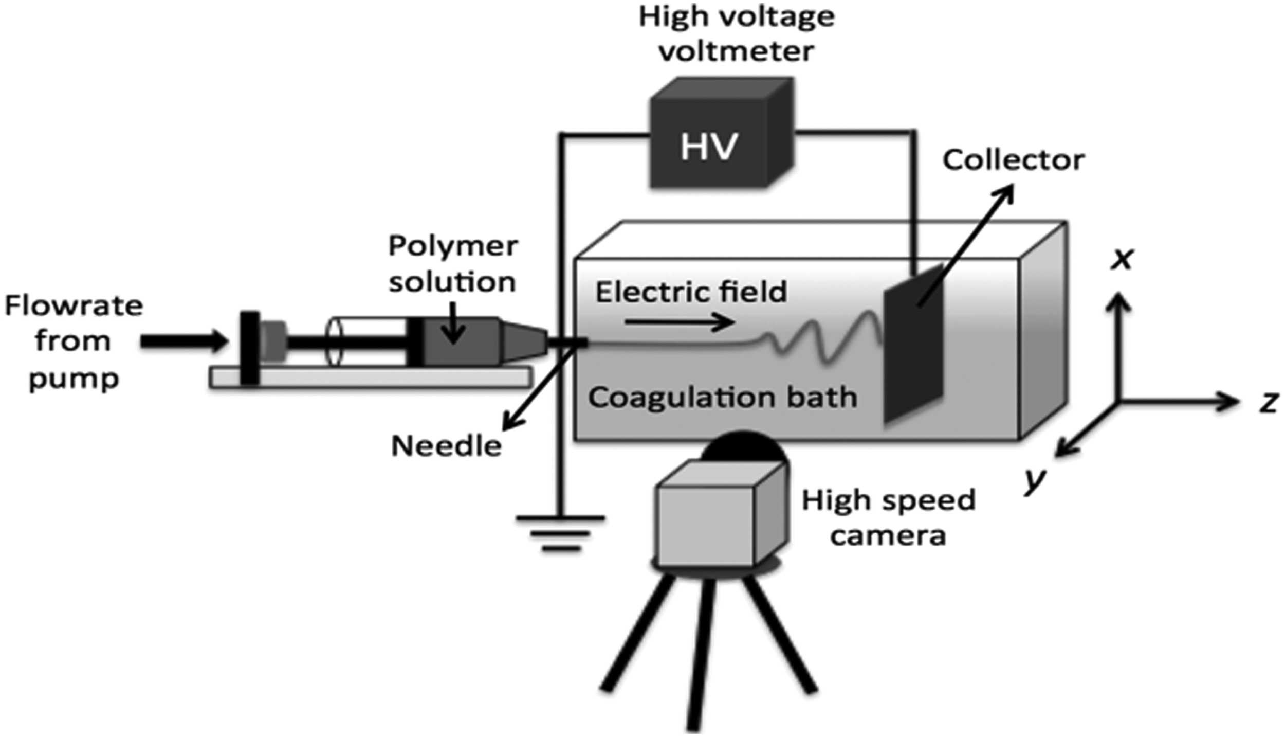
Immersion electrospinning setup. HV, high voltage.
The spinning behavior of the polymer fiber is observed using a high-speed camera (RedLake MotionPro HS-3 with Nikon MICRO NIKORR 60 mm 1:2:8 lens). The images are taken at 100 frames per second with a shutter time of 400 μs. Finally, the images are digitized using MotionStudio × 64 software and are analyzed using ImageJ.
Discretized Model
The immersed electrospinning system is modeled using the bead-spring model; the jet is assumed to be a series of beads attached with springs. The modeling approach is similar to the model used previously in the electrospinning and centrifugal spinning systems.29–32 However, in this study, the drag and dielectric effects on the polymer fiber are incorporated into the model to describe the interaction between the electrically driven jet and the coagulation liquid medium.
For each bead “i,” the radius ri is obtained from conservation of mass equation [Eq. (1)].
The equations of motion for a bead “i” of mass mi, length li, and radius ri are obtained by applying Newton's second law [Eq. (2)]. The position vector
The surface tension force and viscoelastic force are obtained from the work by Divvela et al.
30
and Divvela and Joo.
32
The surface tension force has two components: (1) capillary force and (2) bending force due to local curvature of the fiber. In Equation (3), kc is the local curvature of the fiber and
The viscoelastic force is due to the stress from the solvent and polymer; the solvent is a Newtonian fluid, and the polymer stress is obtained from the Giesekus model.
32
In Equation (4),
The drag force due to the coagulation medium (mineral oil and chloroform mixture) is obtained by considering the average of the drag effects on the upstream and the downstream elements. The drag force has two components as shown in Equation (5): (1) friction drag due to shear stress on the surface of the fiber
where
The friction drag coefficient cf is obtained from the shear stress due to the flow of the surrounding liquid in a thin boundary layer, which forms a concentric annulus around the fiber. At the surface of this boundary layer, the liquid is stagnant and it is not affected by the motion of the fiber. The velocity of the liquid in the boundary layer is in the axial direction and it is radially dependent on no slip condition at the surface of the fiber. The frictional drag force is caused by the shear stress on the surface of the fiber due to the radial gradient of the velocity. In Equation (6), the variable r is the radial distance from the axis of the fiber. The pressure drop along the length of the fiber,
The constants k1 and k2 are obtained from the boundary conditions: (1) Vz = 0 at the boundary layer with
The electric force on a bead “i” is given in Equation (7). The electric field on element i has two terms: (1) gradient of the applied voltage Vo with the spinning length h and (2) Coulombic interaction with the rest of the beads j with charge qj at a distance
The bending motion is induced in the system by applying the nonaxisymmetric normal mode perturbations at the nozzle to the x and y coordinates [Eqs. (8) and (9)].19,29 The terms xs and ys are the coordinates of the stable jet, A0 is the amplitude and f is the frequency of perturbation.
The growth rate of the perturbation
Results and Discussion
Bending instability study
The PAN–DMF solution is spun at 5 and 10 kV (Fig. 2), 42 and all the other conditions are same as mentioned in Immersion Electrospinning Experiment section. The nonaxisymmetric motion of the jet is higher for 10 kV (Fig. 2b). This behavior from experiments is similar to the results predicted from the model as shown in Figure 2c, the coordinate axes are scaled with the radius of the nozzle. The magnitude of the surface charges on the jet increases with the voltage, which leads to large Coulombic repulsions between them. These large repulsions amplify the bending motion of the fiber, forming a spiral with a larger radius. Therefore, from Equation (8), the growth rate is observed to increase with the voltage (and thus electric field at the same spinning distance) from experiments and simulation. This shows that the instability is the conducting mode, as it is electrically driven.

Jet trajectory obtained from
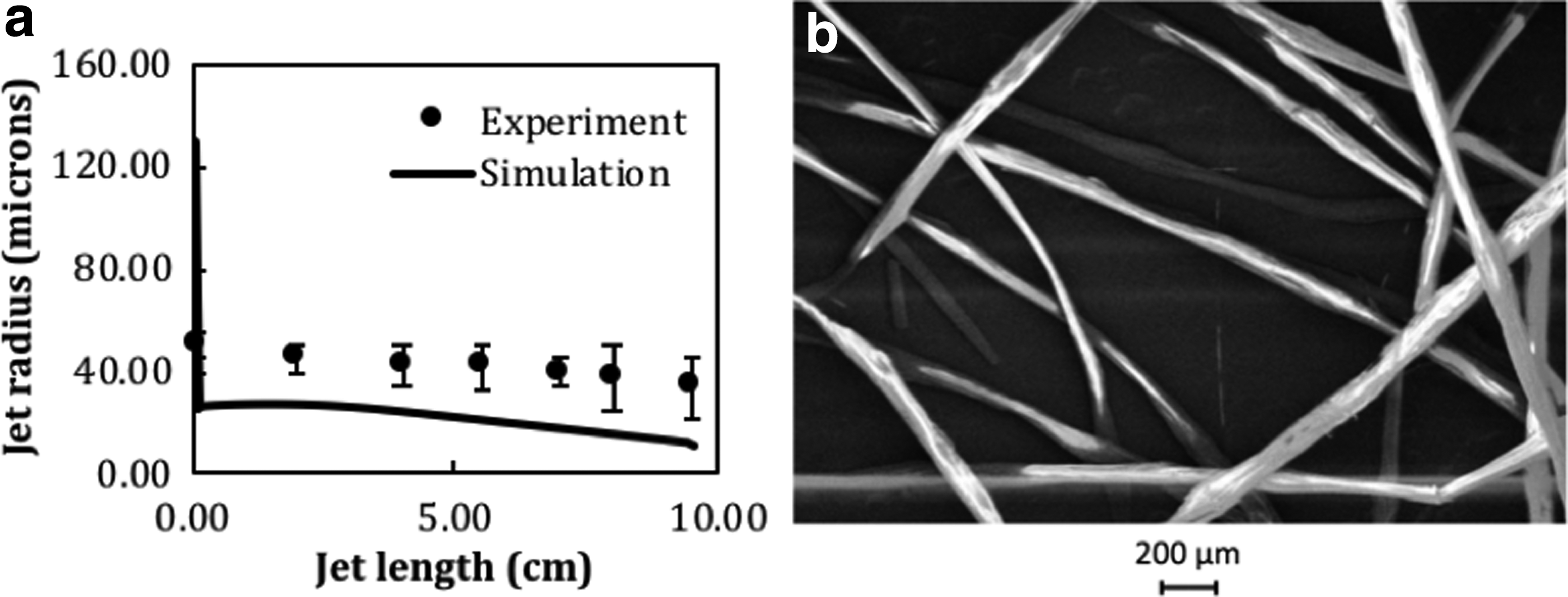
Figure 3a shows the variation of the jet radius along the length of the jet when 7 kV is the applied voltage difference. A rapid thinning of the jet is observed at the nozzle, and the jet radius varies from 130 μm (radius of the nozzle) to 15 μm at the collector. The radius of the jet obtained at different jet lengths from experiments is also plotted in Figure 3a. The field emission electron microscopy image of the fibers collected on the collector at 9.5 cm distance from the nozzle during immersion electrospinning is shown in Figure 3b. The average fiber radius is measured to be 34 μm from the experiment, which is comparable to the simulation result (Fig. 3a).
Electrically controlled patterning of the fiber
The current setup of the immersed electrospinning retards the acceleration of the fiber, which makes it easy to control its motion. The collector in this setup is a black thick art paper, this material does not dissolve in chloroform, and it is nonconductive to the electric field. Four copper plates of size ∼4 × 6 mm are attached to this collector, and the voltage is conducted through these points on the collector. As the fiber reaches a copper plate, the voltage is switched off at that location, and the voltage at the next copper plate is switched on. Hence, for obtaining the square pattern, the order of switching on of the collector plates is 1 → 2 → 3 → 4 → 1, based on the numbering shown in Figure 4. This electrically controlled motion of the fiber forms a square pattern of size 1 cm as shown in Figure 4. The voltage applied to the copper plates is 1 kV and the collector is at a distance ∼1.8 cm from the nozzle. The size and the structural arrangement of these copper plates determine the accuracy of the pattern. In this way, the voltage is applied to a particular point on the collector at a certain time. Therefore, in the bead-spring model, a temporal boundary condition is applied on the voltage on the collector to simulate the guided patterning similar to the experiments.
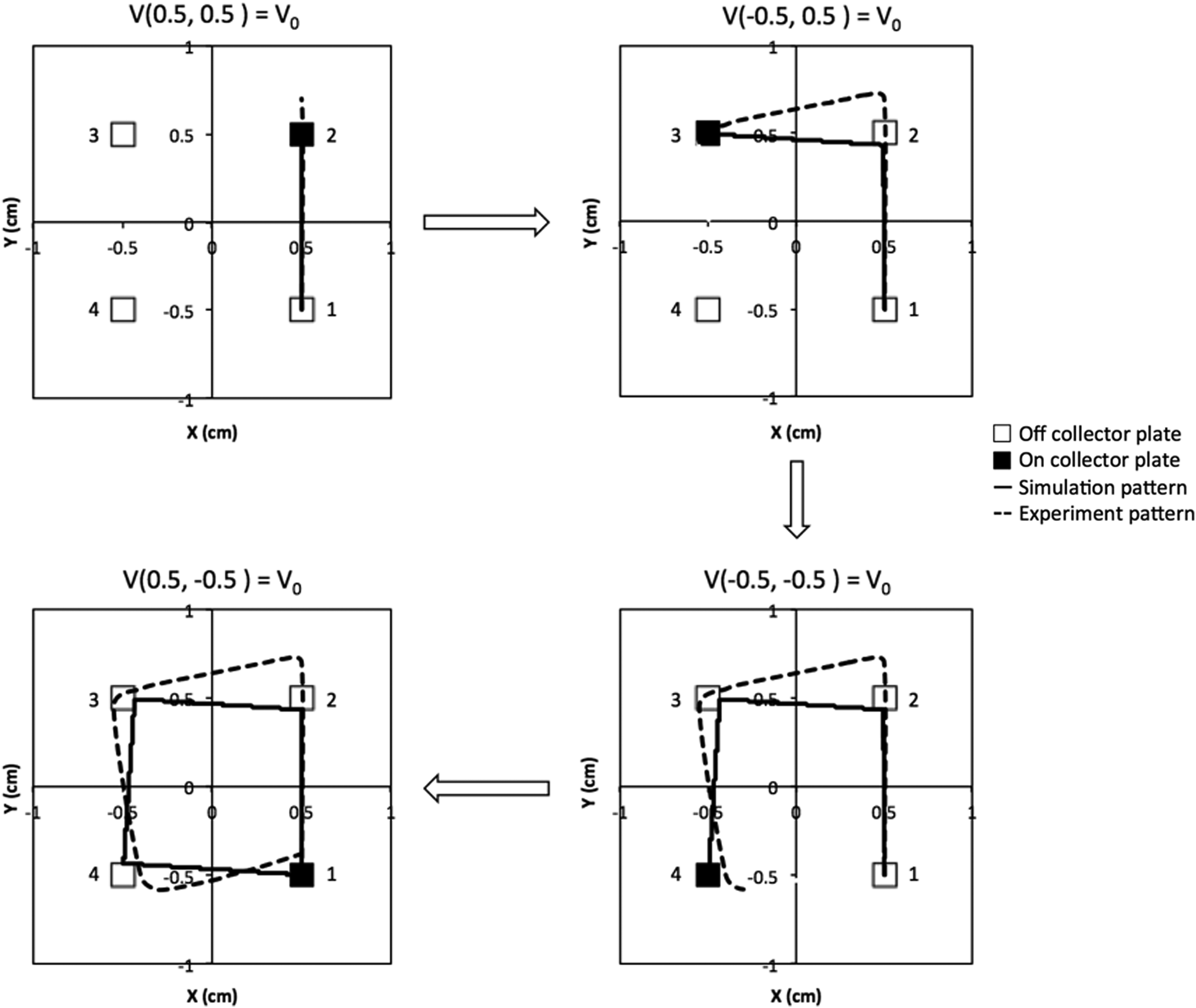
The fiber pattern formed with voltage switching from simulation and experiment.
The pattern formed from experiments exhibits departure from the predicted near square path as there are only four collector points used. This coarse resolution of the lattice points on the collector is not enough to obtain an exact square pattern. In addition, the switching of the electric fields is done manually, so as soon as the fiber reached one collector point, the electric field at the next point is switched on. On an average, the pulse duration is around 5.5 s and the rise time is around 0.5 s. As there is no rise time in the simulation, this manual switching is mainly responsible for the discrepancy in the simulation and experimental result. If the duration of the applied voltage is longer than needed, then the jet will overshoot its position from the actual pattern. If the rise time is longer, then the response to changing the fields may not be quick enough to steer the fiber toward the direction of the next switched on point on the collector.
Despite the discrepancy, both experiments and simulation of immersion electrospinning with electrically guided collector demonstrate that the controlled deposition of an electrically driven jet can be done without any movement of nozzle head and collector. The accuracy of the pattern can be improved with microscale electrode arrays and using MOSFETs for switching the electric field. In addition, we can achieve pattern formation in a regular electrospinning setup (with air as spinning medium) by reducing the spinning distance so that we can obtain jet deposition when it is in the stable region. With this, we can reduce the bending instability of the jet and achieve controlled deposition on the collector for the pattern formation.
The 3D structure of the pattern is obtained from the simulations and the square pattern is observed to be repeated for different layers on the collector. The pattern is formed by considering four collector points on the collector but the dimension of the square formed is 0.1 cm (Fig. 5). The simulation results for four cases (1) shorter switching time (0.13 ms) and resolution (1 mm distance between adjacent collector plates), (2) longer switching time (0.32 ms) and resolution (1 mm distance between adjacent collector plates), (3) optimized switching time (0.2 ms) resolution (1 mm distance between adjacent collector plates), and (4) improved switching time (0.1 ms) and resolution (0.5 mm distance between adjacent collector plates). Initially when the switching time is shorter or longer from the actual switching time and the resolution is poor, the formed fiber pattern is underpredicting or overpredicting, respectively, compared with the desired pattern. Therefore, when the switching time is optimized, in this case it is 0.2 ms and keeping the resolution same, the pattern formed is closer to the square pattern but with few discrepencies. When the resolution is improved to 0.5 mm (distance between adjacent collector plates) by adding eight collector plates instead of four, the fiber forms a square pattern with higher accuracy. In the third case, we can observe that with increase in resolution, the switching time decreased (from 0.2 to 0.1 ms). This is because with increase in the number of collector plates, the distance between the plates reduced, therefore, it takes less time to reach the next switching plate.
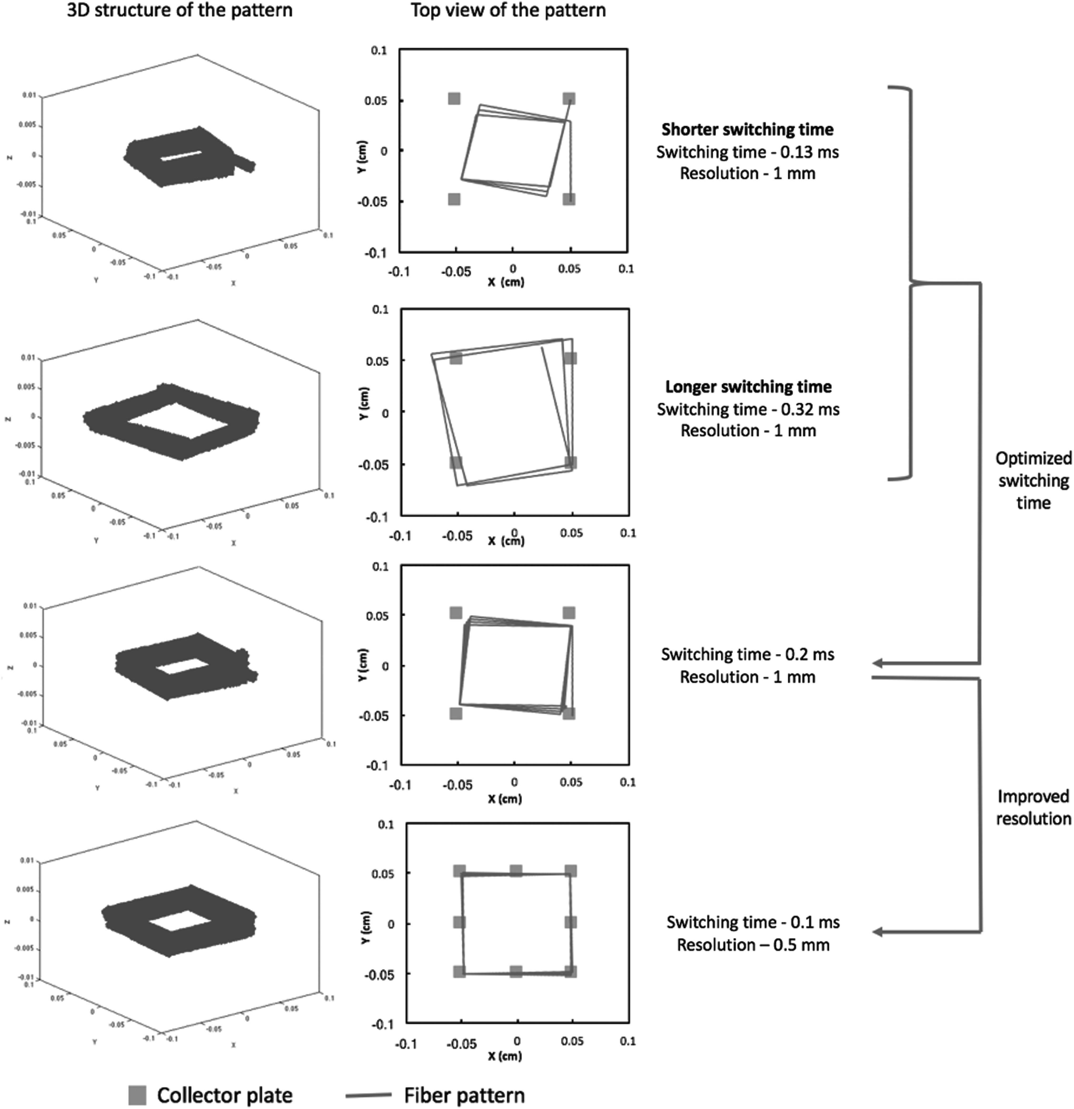
3D structure and top view of the 3D print at different switching times and resolutions. 3D, three-dimensional.
The circle pattern obtained from simulations is studied for two layers of printing shown in Figure 6. The index of sphericity (Is) for the two layers formed at different printing conditions is also shown in Figure 6. When the switching time is not optimized, the second layer was less circular (high Is). In addition, with increase in resolution, that is, decrease in distance between the collector points from 1.53 to 1.04 mm (from 8 collector points to 12 collector points), the pattern was more circular (low Is).
Circle pattern at different switching times and resolutions obtained from simulations. Color images available online at www.liebertpub.com/3dp
Therefore, with the discretized model, we can simulate the fiber motion for motionless 3D printing application and the model also incorporates the different switching times and resolutions of the desired pattern. In addition, the predictions from the discretized model can be used to decide the process conditions for the 3D printing of various other patterns.
Conclusion
In this study, simple 3D printing with the immersed electrospinning setup is studied experimentally and theoretically. To account for the liquid coagulation medium, the drag and the dielectric effects on the polymer are incorporated in the bead-spring model. In addition, to study the bending instability, normal mode perturbations are applied on the jet at the nozzle. The jet trajectory observed with the high-speed camera is similar to the prediction by the model. From these results, we confirmed that the bending instability is electrically driven, as the growth rate is increased with the applied voltage. In addition, the fiber collection is controlled by switching the electric fields among the four copper plates on the collector to form a square pattern. The bead-spring model also predicted a square pattern formation of the deposited jet by applying a temporal boundary condition. However, an exact square pattern is not formed as the manual switching of the electric fields is difficult to effectively steer the fiber. The simulations were also used to study the 3D prints of a square and circular pattern at different switching times and resolutions of the collector plates. This approach for 3D printing can be further developed by using electrode arrays with MOSFETs for switching the voltage at the lattice points. In addition, this approach can be applied to the regular electrospinning setup by reducing the spinning distance to obtain a controlled deposition. Furthermore, as the predictions from the discretized model are similar to the experimental observations, it can be used for designing complex motionless 3D printing.
Footnotes
Acknowledgments
The authors would like to thank Cornell Center for Materials Research Shared Facilities supported through the NSF MRSEC program (DMR-1120296), Cornell University Glass Shop for the fabrication of coagulation bath vessel, and finally Yevgen Zhmayev for his help with the flow visualization study.
Author Disclosure Statement
No competing financial interests exist.