
Abstract
Abstract
It is a significant challenge to fabricate functional stretchable electronics by directly printing Ga-based liquid metals (GLMs) due to their high surface tension. In this study, a coprinting method is developed, in which GLMs are printed together with elastic materials to overcome their poor printability. The continuous contact and extrusion of the external highly viscous elastic materials with its internal liquid metal inhibits the balling of liquid metal, achieving the liquid metal three-dimensional (3D) printing successfully. A multifunctional stretchable inductance sensor was 3D printed at the first time. This sensor can be used to test axial stretch, deflection, and radial stretch, allowing tracking of the status of soft snake structures such as the end executor of endoscope and fingers.
Introduction
S
Recently, stretchable electronics based on Ga-based liquid metals (GLMs) have attracted researchers' attention because GLMs are considered nontoxic liquids 22 with low viscosity (η = 2.4 × 10⁻³ Pa·s) and can remain in a liquid state with high conductivity (σ = 3.40 × 10 6 S/m) 23 at room temperature. However, due to the high surface tension of Ga-based alloys (624mN/m, 534mN/m for EgaIn, 24 Galinstan 25 ), directly printing these materials is quite difficult. Number of studies realized the excellent application prospect of GLMs and have tested many methods to overcome the challenges above, 26 such as photolithography,27,28 imprinting, 23 stencil lithography,29,30 embedded printing process,10,31 injecting,3,6,32–35 and others.
In general, some of these methods directly apply Ga-based alloys to the surface of base materials to make planar stretchable electronics by the modification of base materials.1,5,7,9,36,37 Some methods embed a nozzle into base materials to print planar or 3D circuit patterns.8,15,31,38 As oxide skin can be formed immediately when GLMs are exposed to air and can improve the printability of GLMs, some researchers directly squeeze out GLM droplets in the air and stack them to form a 3D structure. 39 Based on this, some researchers developed a manufacturing process for the mixed printing of liquid metal inks and nonmetal inks. 40 In addition, a new direct printing method that uses a coaxial nozzle to print planar electrics has been described.3,6,41 In this method, elastic material can wrap GLMs after a special modified process such as a thickening process to make some simple planar electrics such as conductor41,42 and capacitance components.6,31
As mentioned above, there are many methods developed for printing liquid metals directly. However, almost all of these methods can only fabricate planar stretchable electronic and have complex printing steps. The material even needs to be modified in some methods. Therefore, these additional conditions limit their applications.
This article described a novel coprinting method that can directly coprint GLMs and an elastic substrate into two-dimensional (2D) or 3D structures to fabricate varied stretchable electronic components. A coaxial nozzle was used in this method, of which the outer nozzle is used to extrude the flexible silicone material, and the inner nozzle was used to extrude the liquid metal. The principle of this method is that the continuous contact and extrusion of the external highly viscous cure sealant with its internal liquid metal inhibits the balling of liquid metal, ensuring the continuous outflow of liquid metal and achieving the liquid metal 3D printing successfully. At the same time, the flexible silicone material also plays an important role in isolating the air, preventing degradation of the liquid metal properties and being a flexible encapsulating material for flexible circuits. Appropriate process parameters are selected to ensure a successful printing process. Compared with other methods, this method can be used to quickly print desired structures with a programmed path.
Materials and Methods
Materials
The Ga-In-Sn liquid metal was obtained from FLYSTONE Company (Zhenjiang, China), and has an electrical resistivity of ∼2.96 × 10⁻⁶ Ω·M and can remain liquid above 10.7°C with a low viscosity of 6.96 m2/s.
A food-grade commercial cure sealant, DOW CORNING 737, was used as the base material to support deformation capacity without modification. It is a viscous liquid at room temperature, but the surface will solidify after 10 min. When the cure sealant solidifies completely in 24 h, it can withstand a temperature range from −65°C to 177°C with fine ductility.
Product package
To seal up the starting port, before the GLMs were injected, a small amount of cure sealant was injected to make a small piece of solid cure sealant pipe to prevent the GLMs from flowing out from the hole. After finishing the production steps, the injection pumps stopped injecting GLMs, but the cure sealant was injected for a longer period of time to plug the port. When the cure sealant had solidified completely, we inserted the wire into the coaxial conductor from both ends as pins. To prevent the GLMs leaking from the ports, we additionally applied some cure sealant around the insert ports.
Results and Discussions
System design
As shown in Figure 1A, a coaxial nozzle-assisted, stretchable electronics 3D printing system was developed for this method. This system consisted of three core parts and some auxiliary devices to make special 3D structure. The core parts were a 3D desktop printer, a coaxial nozzle, and injection pumps. 7

Equipment and products:
The 3D desktop printer, as shown in Figure 1A, was composed of motorized XY stages attached with a coaxial nozzle and a motorized Z stage. The XY stages were precisely controlled to define the path of the coaxial nozzle for planar feature printing, and the Z stage was controlled to connect the layers to form 3D structures. The coaxial nozzle was made of stainless steel and had an inner diameter of 0.34 mm and an outer diameter of 1.3 mm. As shown in Figure 1B, the nozzle had two feed tubes. The GLMs fed into a blunt syringe needle at a certain flow rate of Q1 as core material, and the cure sealant fed into another cavity at a flow rate of Q2 as base material by injecting the pumps in close proximity to a moving substrate. Q1 and Q2 were controlled precisely and the moving stages map out a prescribed pattern.
To fabricate the stretchable electronics, we performed the following steps. First, the injection pumps extruded out GLMs into the inner blunt syringe needle of the nozzle at a suitable flow rate Q1 (above 0.25–0.75 mL/s) and extruded cure sealant into the outer cavity of the nozzle at a flow rate Q2 (above 2–4 μL/min) to make the coaxial fiber. Then, the G-code was input into the computer to control the XY stages of the desktop 3D printer to print the desired electronic circuit. What is more, the motorized Z stage can work with the XY stages to stack the planar electronic circuit into 3D structure. In addition, the motorized Z stage can be used to install other auxiliary devices for the construction of special 3D structures.
Printability
Printability is the biggest challenge to print liquid metal directly. This is because under the combined effect of its large surface tension and the surface oxide skin,43,44 the liquid metal always emerges from the nozzle as a spherical droplet, rather than an ideal column. However, the oxide skin plays an important role in the injecting process of liquid metal. 24 The presence of the surface oxide skin allows the liquid metal to fill the microchannel stably and continuously, instead of flowing out or breaking. Some researchers find that applying pressure to the liquid metal can promote the wetting of the liquid metal on the substrate material. 45 The coprinting process can be viewed as a printed dynamic injecting process. Owing to the excellent printability of cure sealant (as shown in Supplementary Figure S1; Supplementary Data are available online at www.liebertpub.com/3dp), a hollow flexible pipe can be printed directly (as shown in Supplementary Figure S2). During the printing process, the external cure sealant built a hollow flow channel and the liquid metal filled the flow channel simultaneously. The continuous contact and extrusion of the external highly viscous cure sealant with its internal liquid metal inhibited the balling of liquid metal, which ensures the continuous outflow of liquid metal. Using the coaxial fiber printed in this way, flexible circuits containing liquid metal inside can be directly printed. What's more, the actual materials used in this co-printing process are not only limited to cure sealant and liquid metals, as shown in Supplementary Figure S3.
Some complex but important circuits such as a circuit with a negative Poisson ratio structure, as shown in Figure 1C.I, can be printed directly using this process. Figure 1C.II–IV indicates that the circuit can maintain the properties of the negative Poisson ratio structure and remain stable when stretched. Of course, other planar components and 3D circuits such as stretchable antenna, new types of tubular radiators, stretchable wire arrangement, and stretchable 3D circuits can also be fabricated directly, as shown in Figure 1D.I–IV. The details of this system and the process of making different components are, respectively, shown in Supplementary Videos S1 and S2.
The influence of process parameters
As shown in Figure 2A, the flow rate of GLMs Q1 and cure sealant Q2 had a major impact on the formation and geometric parameters of the coaxial conductor. The experiments demonstrate that either a too low or a too high GLM flow rate is inhibitory. It is worth mentioning that the “too low or a too high GLM flow rate” here is relative to the flow rate of cure sealant. The match or mismatch of these two flow rates directly determines the success or failure of the printed structure. A too low GLM flow rate will lead to insufficient GLMs, which breaks the circuit, as shown in Figure 2A (left). This makes it impossible to form a continuous channel in the cure sealant. A too high flow rate of GLMs will promote the assembly of the liquid metal into a ball, as shown in Figure 2A (right). In this study, the flow rate of cure sealant Q2 was 144 μL/min, while the low flow rate and high flow rate of GLMs Q1 were 30 and 280 μL/min. Experimental results showed that in such a Q2, the range of 120–240 μL/min for Q1 was suitable for the coaxial nozzle used in this study. On the contrary, the flow rate of the cure sealant Q2 also should be controlled in a reasonable range. If Q2 is too low, coaxial fiber rupture can occur due to the insufficient supply of cure sealant. A Q2 that is too high may cause cure sealant leakage as a result of the high pressure generated by the excess sealant.

The influence of process parameters:
Overall, production experience has shown that Q1 has a larger impact on the results. Several groups of experiments using a controlled variable were implemented to understand the influence law between the flow rate and geometric dimension of coaxial conductor. Figure 2B shows clearly that with the increase of Q1, the inner diameter will increase gradually and the wall thickness shows the trend of being thinner. These phenomena may be caused by the following reasons. First, growth of Q1 means that GLMs injected from the inner blunt syringe needle of the nozzle will be more compared with the lower Q1, which will cause increased extension pressure on the base material (cure sealant). Second, since the outer diameter of coaxial nozzle is limited by the outer diameter of the nozzle, it is impossible to change the diameter. Instead, the inner diameter size will expand so the wall thickness will become thinner as a result of increased extension pressure. The data shown in Figure 2C confirm that Q2 had almost no effect on the diameter of the coaxial conductor. Although the extrusion pressure from cure sealant to GLMs increased with growth of Q2, the middle channel is still hard to be compressed for the excellent ability of resisting compression deformation of GLMs. Next, an experiment was performed testing the effect of geometric parameters of coaxial conductor on the deformation of 3D spiral structure. To do this, we made a spiral inductive component and measured the biggest deformation of the component by plotting inductance curve.
As shown in Figure 2D, a coaxial fiber with larger inner diameter and thinner wall thickness can tolerate a larger deformation limit since a thinner wall thickness can decrease the connection area between coils. The stretching property will decrease gradually with an increase of the thickness of the material because the elastic modulus will increase and the elastic limit of the material will decrease in this process. We also found that the stability of the spiral inductive component with larger wall thickness of a single coaxial conductor is more suitable for measuring large deflection and radial deformation because a larger wall thickness better prevents distortion of the coaxial conductor.
Coprinting of a multifunctional stretchable inductance sensor
This is the first report of a new type of multifunctional stretchable inductance sensor. Compared with resistance sensors and capacitive sensors, inductance sensors are more reliable and have lower technological requirements because the detection performance of an inductance sensor only depends on the geometric parameters and turn numbers of a spiral pipe and is not affected by conductivity changes of liquid metal. Existing researches have reported the design and application of liquid metal-based inductors used for telemetry system, 46 tensile measurement, 47 and the detection of human motion. 48 However, limited by the manufacturing process, the inductor/coil designed by them are all flat, even the multilayer one, 47 which led to difficulties in installing them on cylindrical surfaces. In this study, we designed and fabricated a 3D spiral coil inductor using the coprinting process. In addition, this inductance sensor is multifunctional, which can be used to measure a series of physical deformations such as axial stretch, deflection, and even inflation (radial stretch).
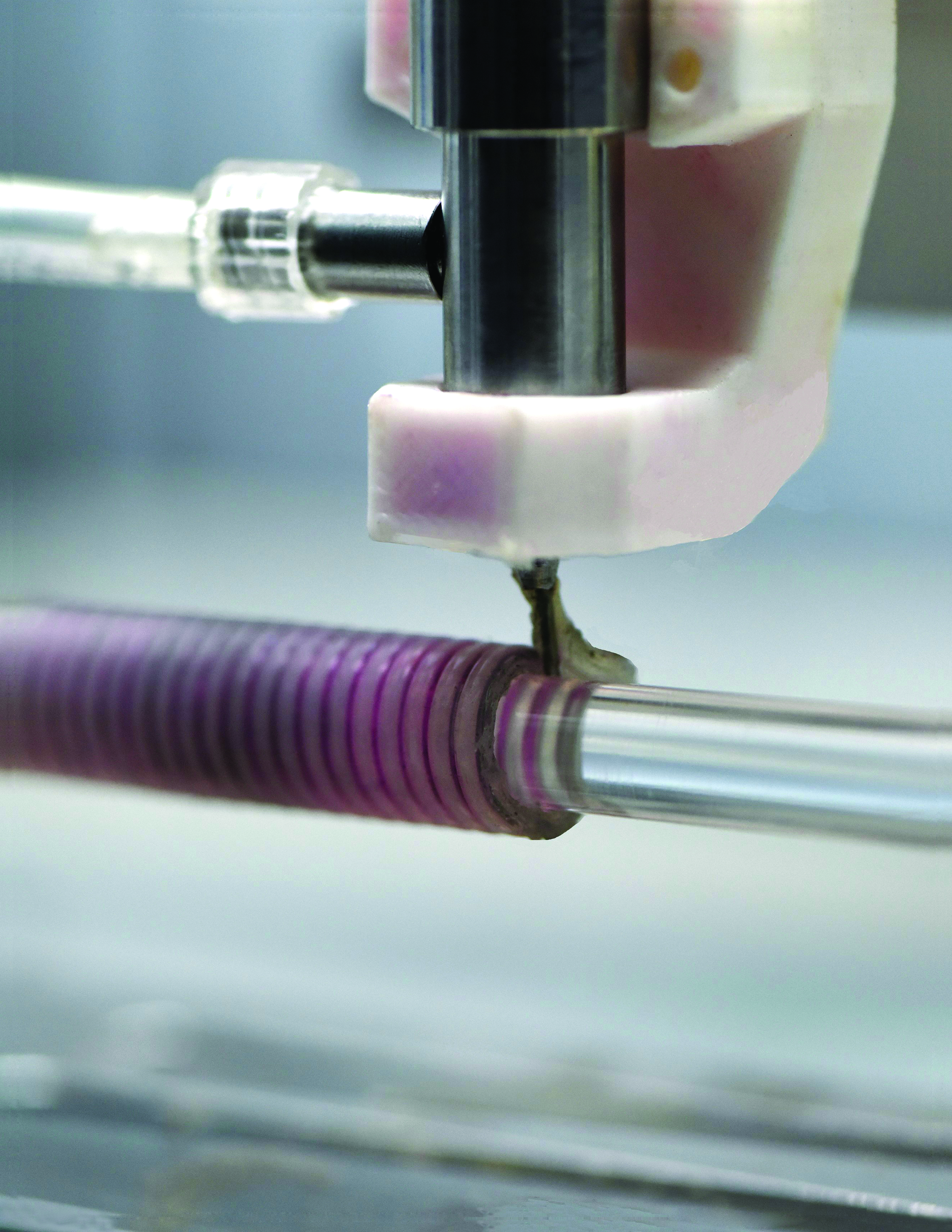
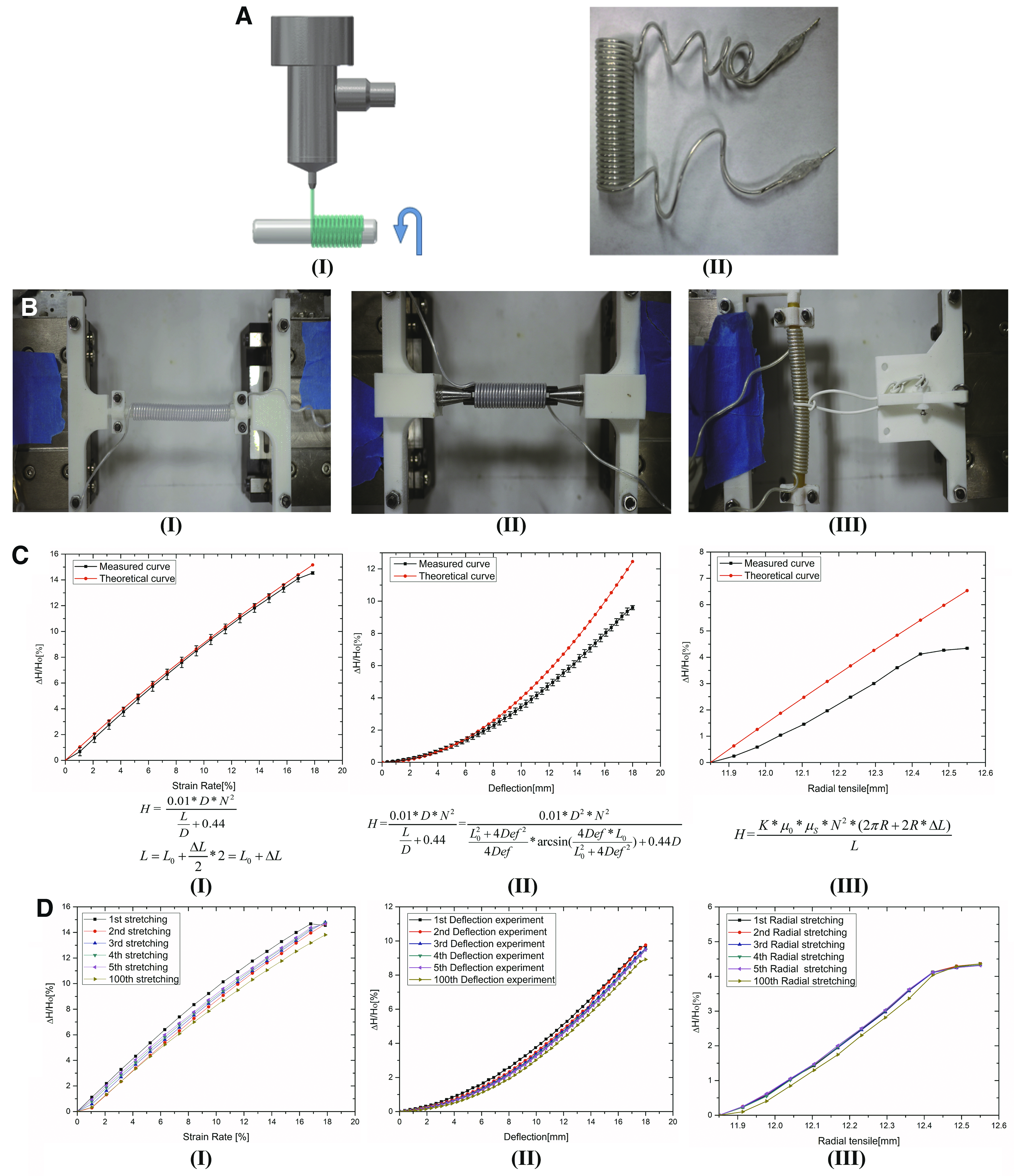
In this study, we utilized the coprinting method described above together with an auxiliary device. As shown in Figure 3A.I, a glass rod can rotate at a certain speed controlled by the computer, causing a single coaxial conductor adhesive on the glass rod to wind into the inductance sensor, as shown in Figure 3A.II. An environmental lubricant, in this case vegetable oil, was daubed onto the glass rod as a separating agent. This process is shown in Supplementary Video S3.
Coprinting of a multifunctional stretchable inductance sensor and calibration tests of the sensor:
Figure 3B.I–III shows the test platforms for the axial stretch test, deflection test, and radial stretch test. The test platforms consisted of three main parts: two linear motors, a motion control card, and a computer. The linear motor, LPP-CR11-0100-05, has high motion precision that can reach 1 μm/ms. The motion control card was obtained from the GOOGOLTECH company, model GT2400-ACC2-VER2.4-AD-DA. In Figure 3C.I, the multifunction inductance stretchable sensor was stretched 100 times repeatedly from 2 sides at a speed of 2 μm/ms from each side in axial stretch tests. In Figure 3C.II, the multifunction inductance stretchable sensor was fixed on a linear motor and another linear motor was used to pull the sensor at 2 μm/ms in deflection tests. In Figure 3C.III, two cones were used to strut the sensor from both ends to produce radial deformation. An advancing speed of each cone was 2 μm/ms. In the Inductance Equations of Sensor Under Different Deformations section, in Supplementary Data, these test methods are reduced to simple models as shown in Supplementary Figure S4, allowing mathematical models of various deformations. The final inductance equations of this sensor under different deformations for the axial stretch test, deflection test, and radial stretch test are shown, respectively, as the following.
where
Figure 3C compares the measured curves and the theoretical curves. The change rule of inductance is consistent in a range of deformation, demonstrating the validity of the theoretical derivations. The measured results will gradually deviate from the theoretical results as the deformation increases, especially in deflection and radial stretch tests. This error is due to the use of approximate mathematical models that were applied to obtain the theoretical curves of deflection and radial tests, because there are no inductance calculation formulas that are completely suitable due to the test limitations (see Inductance Equations of Sensor Under Different Deformations section in Supplementary Data). However, under an uninterrupted frequent deforming-releasing process, the sensor exhibits excellent cycling performance as shown in Figure 3D. The tiny null offset of the sensor is also shown. We next tested the accuracy of this sensor. As shown in Supplementary Figure S5, the precision of the sensors was measured and is extremely high, within the error range of −0.75667% to +2.696667% (axial stretch), −3.52% to +3.1767% (deflection), and −1.05179% to −2.03972% (radial stretch).
Applications
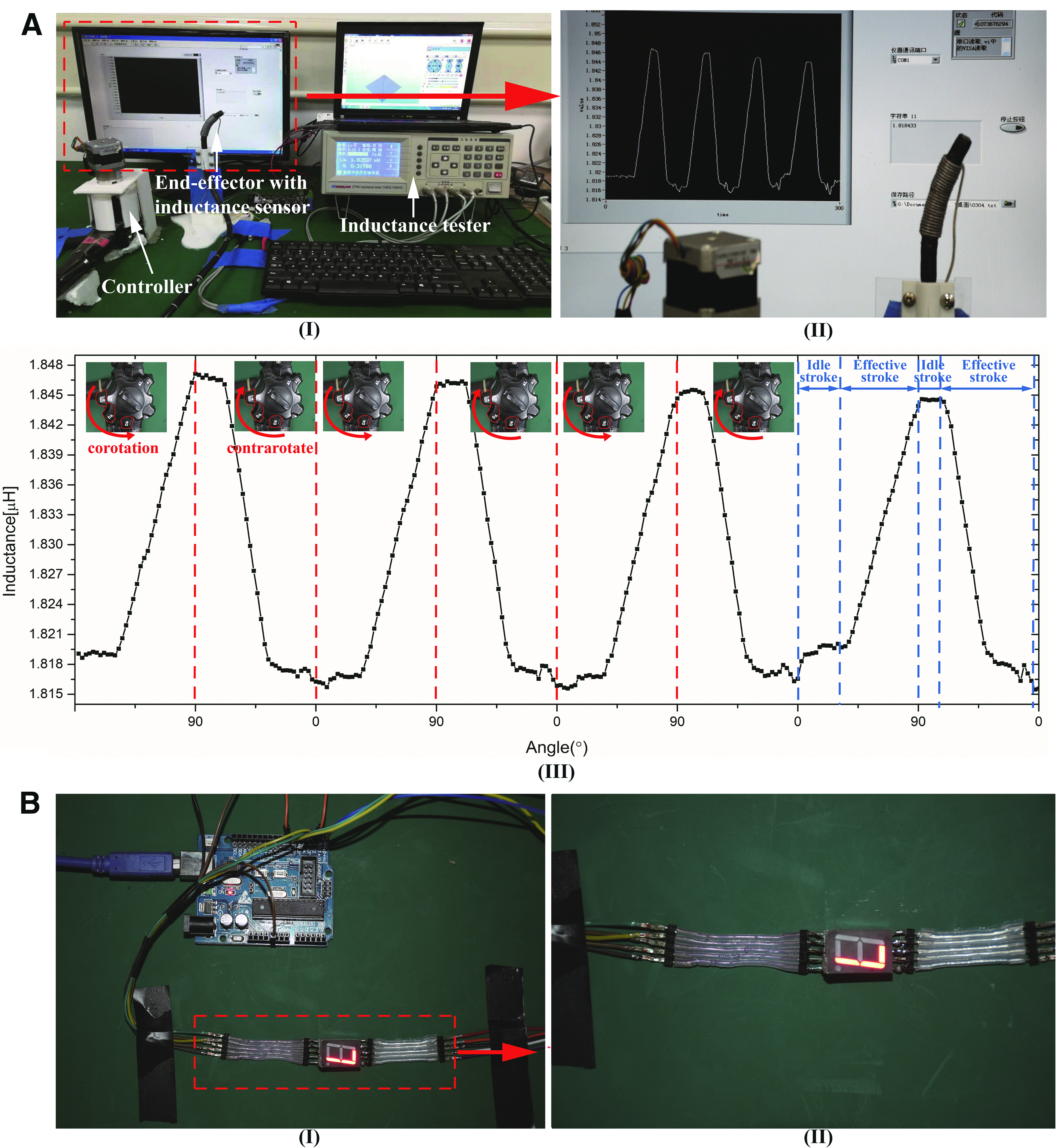
To demonstrate the utility of the sensor as a practical sensor, we pasted both ends of the sensor onto the end effector of an endoscope to measure the spatial motion of the endoscope (Supplementary Video S3). As shown in Figure 4A.I, the motion of the end effector was controlled by the handle. When the handle was turned, the inductance of the sensor changed regularly, which is plotted as a wavy curve shown in Figure 4A.III. The computer recorded these changes as shown in Figure 4A.II. As shown in Figure 4A.III, the sensor had excellent cyclic performance during the process of reciprocating deformation of the end effector. In addition, the inductive response of the sensor was quite sensitive, which indicates that the sensor has great dynamic response and can be used to assess the idle stroke of endoscopic monitoring, an important performance index. These data verified the performance of the sensor.
Applications:
Figure 4B illustrates the stretchable ribbon cable printed directly by the 3D coprinting method. Figure 4B.II shows that the ribbon cable can remain stable when stretched (more details are presented in Supplementary Video S4).
Conclusion
In this article, a simple, rapid, stable, repeatable, one-step additive 3D coprinting method that can coprint both liquid metals and elastic materials directly into 3D structures was developed to fabricate 2D or 3D stretchable electronic components and circuits. The continuous contact and extrusion of the external highly viscous elastic materials with its internal liquid metal inhibited the balling of liquid metal, which achieved the liquid metal 3D printing successfully. A commercially available cure sealant was used without modification as the elastic material to fabricate various kinds of stretchable electronic components. In this work, a novel stretchable inductance sensor was fabricated and demonstrated to be applicable to different test conditions with excellent test performance.
The printing materials used in this method are stable and nontoxic, and the resistance of GLMs is very small. The overall process is simple and stable, and further work is warranted to explore the use of this method to fabricate practical 2D or 3D stretchable electronic components and circuits by writing liquid metals directly. In the future, additional study of the stability of this 3D coprinting method is required to allow industrialization of this method to create novel electronic components and circuits rapidly and conveniently. Furthermore, we appeal to researchers to do more study on the printability of GLMs to optimize the theoretical basis of directly writing GLMs and provide better standards for choosing modified base materials.
Footnotes
Acknowledgments
This article was sponsored by the National Nature Science Foundation of China (No. 51622510, U1609207), the Science Fund for Creative Research Groups of the National Natural Science Foundation of China (No. 51521064), the Nature Science Foundation of Zhejiang Province, China (No. LR17E050001), and the China Postdoctoral Science Foundation (No. 2017M621915).
Author Disclosure Statement
The authors have no financial or nonfinancial relationships to disclose.
References
Supplementary Material
Please find the following supplemental material available below.
For Open Access articles published under a Creative Commons License, all supplemental material carries the same license as the article it is associated with.
For non-Open Access articles published, all supplemental material carries a non-exclusive license, and permission requests for re-use of supplemental material or any part of supplemental material shall be sent directly to the copyright owner as specified in the copyright notice associated with the article.