
Abstract
Abstract
We developed and constructed a novel digital light processing-based microstereolithography three-dimensional printing system capable of producing high-resolution components made of multiple materials in a fully automated, efficient, layer-by-layer manner. A high-contrast digital micro display with a pixel size of 15 μm was used to project customized 405 nm images through a borosilicate glass plate coated with optically clear polytetrafluoroethylene to induce polymerization in a variety of acrylate-based photocurable polymeric resins, where each layer contained multiple resin types. The new minimal-waste material exchange mechanism involves an air jet to remove residual liquid resin attached to the substrate after each exposure, which eliminated the need to use cleaning solutions that have been known to damage printed features. Complex, multimaterial microlattice structures were printed about 58% faster than existing studies that used cleaning solutions. Mechanical tests of tensile specimens demonstrated that the printing process formed sufficiently strong bonds between differing materials. The multimaterial capabilities of the new system, demonstrated as proof-of-concept in this article using photocurable polymer varieties, open doors for potential high-resolution high-efficiency multimaterial fabrication of a broad range of microarchitectures with novel functionalities and optimized performance made of ceramic, metallic, and biomaterials that find applications in the fields of metamaterials, bioinspired soft robotics, biodevices, microelectromechanical systems, optics, and microfluidics. System optimization to facilitate such capabilities remains as motives for complementary studies.

Introduction
T
Compared with the other 3D printing technologies, the digital light processing (DLP)-based 3D printing is a low-cost, fast-speed, and high-resolution 3D printing technology that is based on localized photopolymerization process triggered by the projection of the digitally masked UV patterns onto the liquid surface. Since the printing process takes place in a liquid environment, this technique eliminates the requirement for the use of any support materials in the fabrication of porous or hollow structures, and has, therefore, been used to fabricate lattice metamaterials,14,15 pneumatically actuated soft robots,16,17 and many other structures and devices constructed with trusses or cavities.18,19 In the recent years, the notable advances in this technology include projection microstereolithography that produced micron-scale printing resolution,15,20 continuous liquid interface production enabling 100 times faster printing, 21 and large area projection microstereolithography producing 3D features having feature sizes over seven orders of magnitude from nanometers to centimeters. 14 However, these studies focused on single-material fabrication, and the development of multimaterial DLP-based 3D printing systems remains comparatively limited.
Choi et al. used top down exposure DLP with multiple resin containers in an attempt to reduce the fabrication time, but the use of cleaning solutions to remove uncured resin proved to be damaging to features finer than ∼300 μm.22,23 It was also found that controlling the liquid levels in the multiple containers was difficult and the process was still relatively slow in the fabrication of complex multimaterial parts. More recently, Ge et al. demonstrated multimaterial printing using a top down exposure DLP system, in which a digitally masked UV pattern was directed downward onto the surface of a resin-filled container to fabricate parts having an edge resolution accurate to about 30 μm. 24 However, the material exchange process required draining and refilling of resin within the vat and thereby significantly slowed the process. In addition to the top down exposure approaches, Zhou et al. also developed a multimaterial 3D printing system based on the bottom up exposure method by using a rotating wheel where different materials contained were placed to realize the material exchange. 22 However, the cleaning process involved a brushing process along with ultrasonication, which significantly slowed the process. Instead of placing the material containers on a rotating wheel, Wang et al. built a bottom-up exposure-based multimaterial 3D printing by using the rotating wheel to deliver different material droplets that are selectively deposited onto it. The system was used to successfully fabricate metamaterial structures with negative thermal expansion coefficients; however, the complex material exchange process elongated the fabrication time of a structure of ∼6 mm long, 6 mm wide, and 6 mm high to over 6 h, and the severe material contamination was observed on the printed structures. 7
In summary, it remains a challenge to realize multimaterial 3D printing using existing technologies. The DIW and FDM methods are limited to the submillimeter printing resolution as well as the geometrical complexity of the printed structures, and the Polyjet method is unable to fabricate features smaller than about 200 μm and requires the use of support materials. In contrast, although DLP-based 3D printing ensures a high printing resolution, the currently used material exchange mechanisms make the DLP-based multimaterial 3D printing systems time consuming, and inefficient in material usage. Therefore, a novel material exchange mechanism is highly desired for building a high-efficiency high-resolution DLP-based multimaterial 3D printing system.
Multimaterial 3D Printing System
Setup and material exchange mechanism
We built a novel DLP-based multimaterial 3D printing system that uses a translationally moved glass plate to deliver different material puddles to realize the fast-speed material exchange, and for the first time employs an air jet-based cleaning step to minimize the degree of resin waste and material contamination, and avoid the use of any cleaning solutions that have been proven to be damaging to the printed parts.
The basic components of the apparatus are shown in Figure 1, in which liquid photocurable resins are subjected to UV projections in the upward direction through a 400 × 50 × 5 mm (length × width × thickness) borosilicate glass plate (Borofloat 33, Schott AG, Mainz, Germany, 93% UV transmission) that is covered on the top surface with optically clear polytetrafluoroethylene (PTFE) silicone-adhesive tape (CS Hyde, Lake Villa, IL). The PTFE facilitates the separation of the printed layers from the glass plate such that new layers adhere to the printing platform but not to the glass plate (Fig. 1a). The plate is horizontally translated using a translational stage (LTS150, Thorlabs, Inc., Newton, NJ). Customized 405 nm wavelength UV patterns are projected using a DLP light engine (CEL5500, Digital Light Innovations, Austin, TX) upward through the glass plate (Fig. 1b).
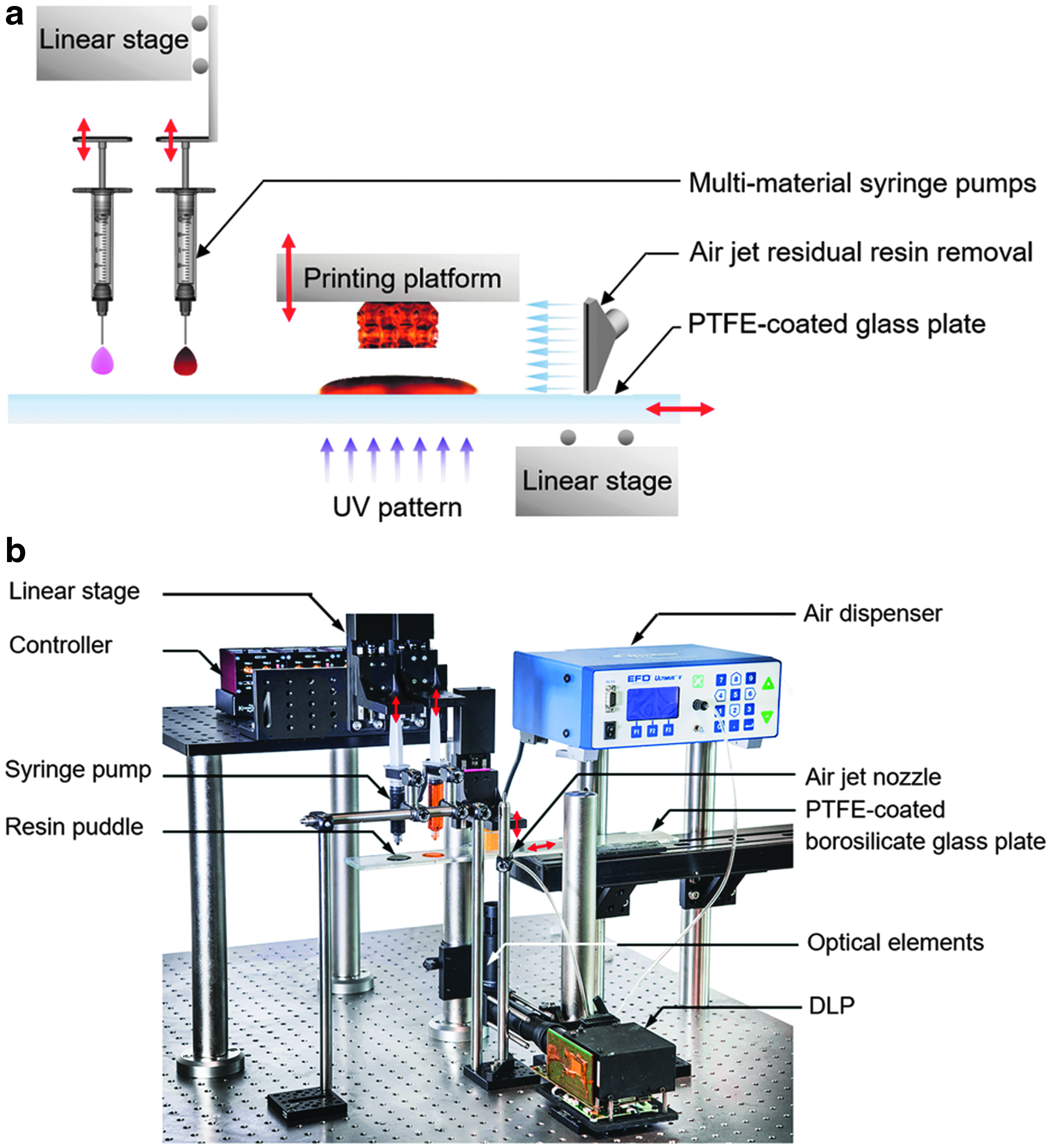
Components of the DLP-based 3D printing apparatus. Labeled
Figure 2 shows the efficient material-exchange mechanism where the glass plate also serves to deliver various material puddles to the printing platform to enable the multimaterial printing. Various photocurable resins are contained in different syringes and deposited on the glass plate by automatically controlling the linear stages connected to the syringes (Fig. 1). The material exchange mechanism incorporates a 5 s blast of a 0.5 MPa air jet through 2 mm diameter tubing placed ∼20 mm away from the substrate (Fig. 1), controlled in sequence using a high-precision dispenser (Ultimus V, Nordson EFD, Nordson, OH). Figure 2 shows the primary steps used in the fabrication of multimaterial components. In Step 1, the printing platform is above the glass plate at a distance equal to the prescribed layer thickness. In this position, as illustrated in Step 1 of Figure 2, the liquid resin of material A is contained between the printing platform and the glass plate. Then, a UV pattern of the regions within the layer containing material A is projected, leaving blank spaces for material B. In the next step, the printing platform is elevated to a height of 5 mm above the glass plate while the puddles are positioned beneath their respective syringe pumps. As shown in Step 2 of Figure 2, the puddles are refilled while the air jet is exposed to clean any remaining liquid resin attached to the printed part. The glass plate is then horizontally translated to position the puddle containing material B beneath the printing platform. Next, the vertical stage is lowered to submerge the printed structure within the liquid resin at a distance equal to a single layer thickness above from the PTFE-coated glass plate. In Step 3 (Fig. 2), the image is projected to the blank space next to the fraction printed in the same way as in Step 1, but using material B. In this moment, the two-material layer is fully formed, and the vertical stage is raised by 5 mm followed by horizontal translation of the glass plate to the position shown in Step 4 of Figure 2 for cleaning and puddle refilling. The cycle is then repeated for subsequent layers as evident in the Supplementary Video S1 (Supplementary Data are available online at www.liebertpub.com/3dp).

Illustrations of the positions of the glass plate used in each step of multimaterial fabrication.
The electronic components of the apparatus are controlled in sequence using codes written in LabVIEW 2016 (National Instruments, Austin, TX). As explained in the companion work of Ge et al., 24 a 3D computer-aided design structure is sliced into a series of 2D images with a prescribed layer thickness. The 2D images are later transmitted to the DLP-based UV projector as the dynamic mask that irradiates the modulated near UV light (405 nm) with the corresponding 2D image for each layer onto the surface of polymer resin. The UV radiation triggers the photopolymerization that connects monomers, oligomers, and crosslinkers to macromolecules, and solidifies the liquid solution into a solid patterned layer.
Materials
Table 1 gives the properties of the commercial photocurable resins designed for stereolithographic 3D printing that were used in the experiments, in which the values were obtained from the manufacturers: 3DM-ABS (Kudo 3D, Dublin, CA), VeroClear, VeroWhite, and VeroBlack (Stratasys Ltd., Eden Prairie, MN). Fluid viscosities were measured using a hybrid rheometer (Discovery HR-2, TA Instruments, New Castle, DE) using a 20 mm flat tip over a 50 mm Peltier plate. Despite the use of commercial resins in this work, the system can fabricate components made of a broad range of photocurable resins including various types of monomers, oligomers, initiators, and absorbers suited for various applications.7,15,17,21,24
The values other than viscosity were obtained from the manufacturers.
System Characterization and Demonstration
DLP image analysis
The first step was to characterize the UV projection at the focal plane as produced by the DLP light engine. As shown in Figure 3a, the input of squares and lines having widths and thicknesses ranging from 1 to 14 pixels into the DLP produced images ranging from 51 to 726 μm. Projected patterns, such as those in Figure 3a and b(i), were captured for analysis at the focal plane using a digital single lens reflex camera with 37.9 million 4.88 μm wide pixels (D810, Nikon Corp., Tokyo, Japan). The quantitative analyses of these images were conducted using digital software ImageJ. The camera's sensor was placed about 75 mm away from the leading optical element. Although this section's image characterization was performed using the optics provided by the manufacturer, the fabricated components in Structure Fabrication section made use of planoconvex optical elements to produce a field of view of 16 × 12 mm and a pixel size of <15 μm, which could be further reduced to the submicron scale with the use of objective lenses.
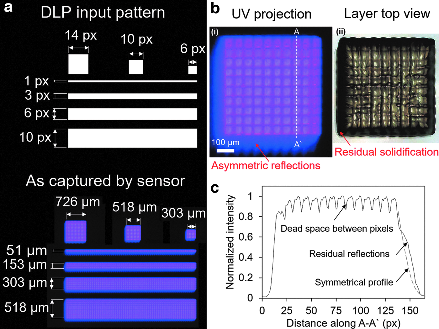
Characterization of the shape and uniformity of UV patterns projected by the DLP light engine.
A 3D digital microscope (RH-8800, Hirox Co Ltd., Tokyo, Japan) was used to quantify thicknesses and surface topographies of liquid and solidified layers with vertical and lateral accuracies of ±5 μm. A close investigation of the 10 pixel-wide square (Fig. 3b) reveals that there were asymmetric reflections in two of the four edges, presumably due to the stray light resulting from the tilting of the micromirror array. Figure 3b also shows that the shape of a solid layer produced using this pattern corresponded to the overall shape of the image, including the residual solidifications in two of its edges. The pixels in the top and right sides appeared well defined (Fig. 3b), whereas the left and bottom edges were smoothened and expanded by the undesired solidification caused by the reflections. The stray light is also evident in the normalized light intensity plot of Figure 3c, which shows that the shape of the curve was not symmetric as expected. Moreover, the smaller peak at the left side of the plot in Figure 3c compared with the rest of the peaks demonstrates the superposition of the neighboring reflections that occurred in the direction toward the bottom left of the square pattern. However, this effect produced an error of <5% in the lateral edge definition, and corrective measures remain as the objective of a future study. The dead space between pixels evident in the light intensity plot of Figure 3c was apparent in the topography of the printed layer in Figure 3b(ii). This showed that the surface roughness of printed layers was highly sensitive to the uniformity of the projection. In summary, despite the variations in the light intensity across pixels (Fig. 3c), our DLP-based 3D printing system enables the high-resolution features as demonstrated in Structure Fabrication section with the use of optical elements that reduced the pixel size to about 15 μm.
Resolution control
To secure high-resolution 3D printing, we investigated the effects of curing time on curing width and depth. As depicted in Figure 4a, we irradiated a pattern of UV lights onto polymer resin placed between the glass plate and the printing platform. The distance between them was relatively large such that the height of the pattern in the plot of Figure 4b did not reach the printing platform. The experiments revealed that resin solidification began to occur at the glass–liquid interface, then propagated upward toward the printing platform with increasing exposure. Figure 4b plots the width and height of a 518 μm-wide square pattern versus exposure time using 3DM-ABS and VeroBlack. It is seen that the width and height of layers made of both materials increased in a less-than-linear manner with increasing exposure, with the height increasing at a greater rate than the width. This is explained by the expected reduction in intensity as light propagates through any liquid as explained by the Beer–Lambert Law. 25 The light intensity further reduced with increasing layer thickness to give the decreasing slope of the height plots shown in Figure 4b. This effect also produced an edge slope of about 75° as shown in the surface topography of the printed layer shown in Figure 4c. It was of interest whether the use of a clear resin such as VeroClear would reduce the edge slope, but the measured edge slope of a similarly sized layer printed using VeroClear remained constant at about 75°, indicating that resin clarity did not have a significant effect on the edge slope. Figure 4b also shows that an exposure of 0.5 did not produce a solid layer using VeroBlack, indicating that the total energy delivered to the resin over the exposure was less than the minimum required for the cross-linking reaction initiation. This minimum threshold was lower for 3DM-ABS, since, as shown in Figure 4b, a solid layer did indeed form at this energy level.

Characterization of the printing resolution.
Structure fabrication
Since the initial distance between the printing platform and glass plate is unknown, each printing process requires the use of a sacrificial layer as illustrated in Figure 5. This is done by manually positioning the printing platform to within 1 mm away from the glass plate, followed by a relatively long exposure; for example, 60 s, to ensure that the gap is filled with a layer that adheres to the top plate. For all subsequent layers, the platform is raised by a distance equal to the desired layer thickness after the printing of each layer.

Schematics showing the steps in the formation of the sacrificial layer used to initiate the printing process.
Figure 6 shows high-resolution (15 μm pixel size) single- and two-material structures printed using the materials given in Table 1. The prescribed layer thicknesses, corresponding to the distance by which the printing platform elevators were moved, was 25 μm. These substrates demonstrate the high-resolution capability of the system. Figure 7a and b displays structures printed in which every layer consisted of two different materials. These structures took ∼2.2 times longer to fabricate than the single-material process for otherwise identical conditions. This was because for a given layer, the two-material process required two equal-duration exposures, translational motion of the glass plate, and air jet cleaning as explained in Multimaterial 3D Printing System section. For example, the multimaterial lattice structures shown in Figure 7a–c consisted of 126 25 μm-thick layers and took about 75 min to fabricate.

Single and two-material structures fabricated using 3DM-ABS alone or 3DM-ABS and VeroBlack. Exposure times: 2.5 s for 3DM-ABS, 3.5 s for VeroBlack.
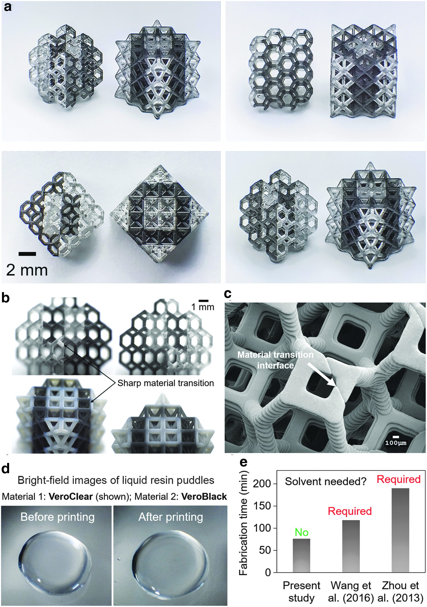
Multimaterial fabrication capability and performance of the present DLP-based system. Two-material lattice structures fabricated in a fully automated manner using
The effectiveness of the air jet cleaning process is demonstrated by the sharp transition from one material to another as evident in the scanning electron micrograph of Figure 7c as well as the top-view photographs of VeroClear puddles before and after printing (Fig. 7d) with the second material as VeroBlack, which show minimal cross-contamination (i.e., perfusion) between the two materials during the exchange process. As was shown in Figure 2 in Setup and Material Exchange Mechanism section, the air blasting process was directed at the printed substrate only without removing the puddle, thus preserving the puddles, which significantly reduced the degree of material waste. A 5 s blast of the 0.5 MPa air jet at a standoff of 20 mm was found to sufficiently remove any liquid resin attached to the substrate, presumably facilitated by the resins' relatively low viscosity given in Table 1. Although our process was relatively efficient, the material waste could be further-reduced to virtually zero by collecting and recycling the air-blasted liquids of various types into separate catcher bowls. Multiple-vat multimaterial DLP-based systems such as that of Zhou et al. dip printed structures into isopropyl alcohol (IPA) followed by submergence into a secondary resin vat after each exposure, increasing the likelihood of contaminating the large volume of secondary resin and potentially rendering it unusable. 22 Comparatively, our system affords the advantage of eliminating harsh cleaning solutions without introducing any additional resin waste. The 6 mm3 lattice structure shown in Figure 7c required about 8 mL of resin.
Figure 7e compares the duration required to print a 6 mm long, 6 mm wide, and 6 mm high lattice structure consisting of a total of 120 layers, each 50 μm thick, between the present DLP-based multimaterial system and those of Wang et al. and Zhou et al.7,22 It is seen that the present system was ∼36% and 80% quicker than those of Wang et al. and Zhou et al., respectively.7,22 Moreover, the present apparatus did not require the use of harsh cleaning solutions such as IPA, known to chemically damage solidified photocurable resins upon exposure. In addition, the process time could be significantly reduced chemically using photoinitiator additives with higher sensitivity to the system's 405 nm irradiation, or mechanically by utilizing commercially available high-speed translational stages with 400 mm/s maximum velocities as compared with the presently employed 50 mm/s stages.
Interfacial bond strength
The strength of the bond formed between layers of differing materials was investigated using tensile specimens made of VeroBlack and TangoPlus materials in the following configurations shown in Figure 8a: entire specimens made of (i) VeroBlack or (ii) TangoPlus, and (iii) half-and-half composite specimen made of VeroBlack and TangoPlus. TangoPlus was selected for its flexibility compared with VeroBlack, as evident in the uniaxial tensile test plots shown in Figure 8b. Figure 8a also shows that the fracture paths in all three specimens occurred in the narrow cross-section, and away from the Vero–Tango interface in the composite specimen, demonstrating that the interfacial bond strength was reasonably good. Young's moduli, computed using the data shown in Figure 8b as 129.9, 1.1, and 0.4 MPa for Vero only, Vero–Tango, and Tango only specimens, respectively, were much smaller than those provided by the manufacturer in Table 1. The much smaller stiffness indicated that the light intensity and exposure time used in the present experiments did not complete the cross-linking reaction, that is, the solid layers produced formed by gelation rather than complete polymerization. It should be noted that the samples were not treated in a UV oven after printing to prevent nonuniformity in stiffness, since, although the exterior may have been further stiffened, the UV rays would not effectively reach the core. In summary, the finding may have important implications in tailorable mechanical properties through light control.
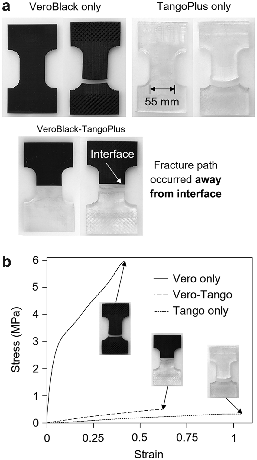
Characterization of the bond strength between different materials.
Conclusions
Existing 3D printing systems developed for the fabrication of multimaterial components using DLP-based stereolithography are relatively slow, wasteful, and are unable to print high-resolution structures, and require the use of harsh cleaning solutions that damage fine details within printed substrates. This study developed a novel high-resolution and high-efficiency bottom-exposure DLP-based microstereolithography system using a new air jet-assisted material exchange mechanism.
It was found that the surface topography of solid layers formed in the bottom-exposure configuration was highly sensitive to the uniformity of the light intensity, that is, the layer surface waviness closely depicted the measured profile of the light intensity. Moreover, the width and height of solidified layers increased in a less-than-linear manner with increasing exposure time. The edges of these layers were not vertical and had an edge slope of ∼75°. Successful fabrication of high-resolution two-material lattice structures demonstrated the effectiveness of the material exchange process by showing minimal resin cross-mixing during the printing. For identical conditions and substrate, a two-material process was about 2.2 times slower than the single-material process, but could be sped up using faster translational stages through hardware upgrade. The air jet-assisted material exchange mechanism minimized the degree of material waste, since, in contrast to previous studies such as that of Wang et al.,7,22 this study did not dispose of the liquid resin puddles after each exposure. Uniaxial tensile tests of composite specimens made of different materials revealed that the fracture path occurred away from the material transition interface, demonstrating that the process can produce reasonably strongly bonded multimaterial layers. Taken together, the advantages such as relatively quick and efficient printing of high-resolution multimaterial components open doors to a broad range of applications involving any combination of polymers, sintered ceramics, metallic, or organic biomaterials, including but not limited to negative thermal coefficient metamaterials, 7 microelectromechanical systems made of sintered ceramic, metals, or fused silica glass composites,14,26,27 3D microfluidic platforms made of functional embedded channel features, 28 biosensor microdevices using varieties of hydrogels, bioinspired microsoft robotics, fiber-optical components using materials with varying refraction indices, functionally graded or voxel microstructural components, and functional tissue scaffolds.
Footnotes
Acknowledgments
The authors gratefully acknowledge support from SUTD Digital Manufacturing and Design Centre (DManD) funded by the Singapore National Research Foundation. Q.G. acknowledges SUTD Start-up Research Grant.
Author Disclosure Statement
No competing financial interests exist.
References
Supplementary Material
Please find the following supplemental material available below.
For Open Access articles published under a Creative Commons License, all supplemental material carries the same license as the article it is associated with.
For non-Open Access articles published, all supplemental material carries a non-exclusive license, and permission requests for re-use of supplemental material or any part of supplemental material shall be sent directly to the copyright owner as specified in the copyright notice associated with the article.