
Abstract
Abstract
The Jammed Architectural Structures (JAS), presented in this article, are 3D-printed fully reversible architectural elements, composed of low-cost loose bulk material, and string reinforcement. The material system is based on crushed stones (known from the railroad industry) and recycled string. If poured without any containment, the stones naturally form a pile. However, in the case of our JAS, a robotically placed string is applied to confine and transform the bulk material into geometrically differentiated structures at an architectural scale. Since this is a nonstandard material system, a combination of techniques from the fields of architecture and materials science is necessary to, first, understand the material behavior and consequently to inform the processes of design and construction. This article investigates the load-bearing capacities and the deformation of our JAS by presenting results from a series of uniaxial compression tests and fiber-optic measurements. Findings from these tests serve to inform the generative logic of the string layout, which is not only key to the design of our JAS but also responsible for the material properties of the system. The developed methods are validated at an architectural scale through the design and construction of a wall segment loaded with concrete slabs. The presented results prove that the string/stone material system has the potential of becoming an actual load-bearing building material and forms the basis for material-informed design strategies for JAS.

Introduction
In materials science, granular systems form a distinct class of materials known as fragile matter. 1 They are defined as a large number of unbound particles, for example, beans, powders, grains, and stones. Granular materials are characterized by their capacity to change their compositional state from solid to fluid, depending on the external forces acting on them. For instance, if a box filled with stones is gradually tilted, after reaching a certain angle of inclination (the so-called angle of stability), the upper surface will erode. The transition from one state to the other is known as the jamming transition 2 and if the particles are jammed and locked in place, they form marginally stable 3 structures. On one hand, this suggests that structures built with granular materials without permanent bonding are fully reversible and thus considered sustainable and recyclable. On the other hand, considering granular material for application in architecture, the concept of marginal stability is rather unconventional, since building materials are in general supposed to be nonfragile—buildings are always designed to be stable. Therefore, to investigate the architectural applications of granular systems and to study their potential of becoming effective building materials, it is crucial to face the question of stability.
Load-bearing capacities of granular-based architectural elements
In the last decade, researchers from the disciplines of both architecture and materials science successfully realized freestanding basic architectural elements such as walls, columns, and even enclosed dome-like structures with designed particles.4,5 Conceptually, designed particles suggest that the shape of the single element can be designed to predefine the behavior of the bulk. If a large amount of elements are poured, they jam due to the local interactions encoded by their form and allow the construction of freestanding and stable structures. However, only some of these structures have been tested for their load-bearing capacities.
One example is the project Z-shape 6 (2016), a collaboration between physicists at the Jaeger Lab at the University of Chicago and the artist Dan Peterman. Their arc-shaped structure was built from bent recycled plastic pieces and its load-bearing capacity was demonstrated by a person standing on top of it. In preceding studies, 7 the Jaeger Lab looked into the simulation and realization of freestanding columns made of 3D-printed z-shaped particles. Cylindrical samples with diameters between 4.5 and 5 cm and a minimum height-to-diameter ratio of 2:1 were tested for their stability under the impact of axial forces. The important conclusion of their study was that if jammed structures composed of unbound granular materials are prestressed through compression, the number of contact points between the individual particles and packing density increases. Thus, these structures become more stable, if they are exposed to axial forces.
Another line of investigation in the scope of granular materials for architecture is to use bulk aggregates. For instance, Rock Print, 8 realized in 2015 as a collaboration between the groups of Gramazio Kohler Research (ETH Zurich) and the Self-Assembly Lab (MIT), was a four-meter-tall structure standing on four legs and built with lightweight glass foam aggregates and string. Subsequently, Rock Wall, 8 a project realized in 2017 at MIT, was built with rocks and loose coconut fibers. Both projects investigated the application of simple and available granular materials for the construction of architectural elements. However, the load-bearing capacities of these structures were not explored within the scope of the research. In an earlier project called Tent Pile, 9 realized in 2013, designers from the Formlessfinder architectural office used a sand pile as structural support and tested its capacity to withstand the weight of a glass/aluminum canopy. This experimental project suggests using a simple natural substance such as sand as an actual load-bearing building material for architectural-scale components.
Load-bearing Jammed Architectural Structures
Jammed Architectural Structures 10 (JAS) is a research project that investigates on a building material system for the realization of vertical architectural elements such as walls or columns, which become more compact and solid under the applied compression load of the ceilings and/or multiple stories in a building. Figure 1 shows an example of a wall segment with dimensions of ca. 1700 × 1000 × 2700 mm loaded with 2.6 t heavy concrete slabs. Unlike structures composed of designed particles, our JAS rely only on the combination of low-cost materials such as railroad ballast and textile string placed in alternating horizontal layers by an industrial robotic arm, and without using formwork (Fig. 2).

Loading of JAS (1700 × 1000 × 2700 mm) with concrete slabs (M = 2.6 t). JAS, Jammed Architectural Structures.
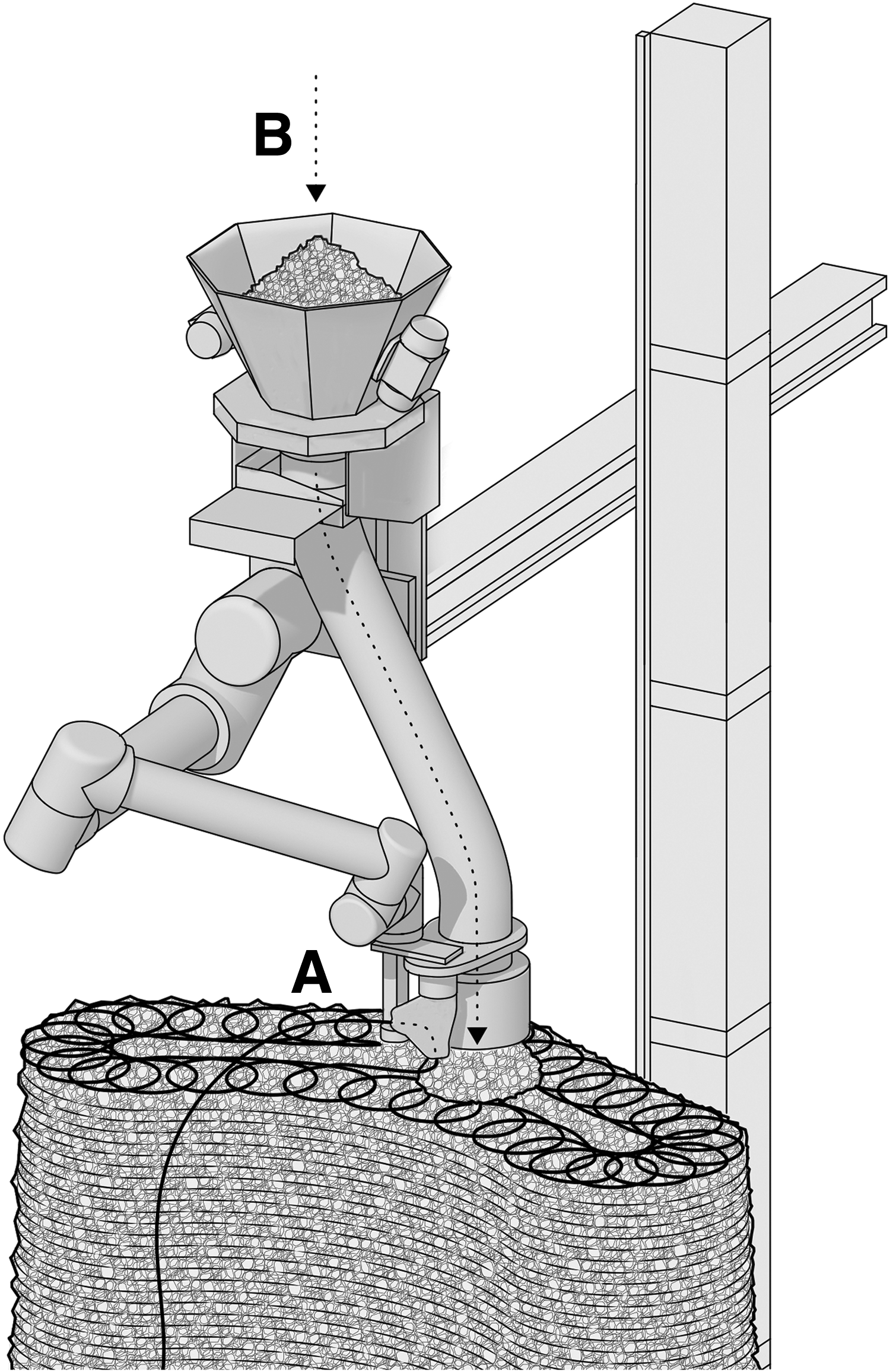
Diagram of the buildup of JAS by successively fabricating layers of
The global stability of our JAS is related to the local interaction between the gravel and string and is based on gravity and friction. On the granular scale, this behavior was analyzed by discrete element simulations, within which the motion of each interacting grain and string segment was calculated. Simulations with varying frictional coefficients, string stiffness, and stone size distributions revealed their role for the overall mechanical behavior (see “Discrete element modeling of free-standing wire-reinforced jammed granular columns”—an article accepted for the Journal Computational Particle Mechanics 2018). Within this material system, the string has a confining function and is responsible for holding the stones tightly together. Thus, the design of our JAS and the properties of the material system depend mainly on the pattern in which the string is arranged. The string layout and the arrangement in layers allow the production of geometrically differentiated architectural elements distinct from the form poured stones naturally adopt, the pile. Any slight change in the pattern parameters influences the behavior of the material system.
The presented article describes and analyzes experiments on the JAS material system under loading conditions. The Materials and Methods section begins with a brief introduction to the two material components, the stones and the string, followed by the generation of the string layout and the description of the fabrication method. Then, the article presents two adapted methods for studying the material behavior, applied in the unconfined uniaxial compression tests and the fiber-optic measurement tests. These methods—appropriated from the fields of engineering and materials science—serve to improve the understanding of the material performance under compression. The section concludes with a description of a large-scale experiment, shown in Figure 1, with the purpose of validating the developed methods at an architectural scale. Fundamental findings on the load-bearing capacities and the deformation of our JAS are presented in the Results section. The article concludes with the extracted information on the material system's behavior and the relevance of the developed methods. It discusses the results and suggests further lines of investigation for the architectural potential of the material system.
Materials and Methods
Strings and stones
The stones for the fabrication of all prototypes, described in this article, are low-cost crushed porphyry (16–32 mm). This largely available natural resource is extracted at Porphyrwerk Detzeln GmbH, 11 a local stone quarry, and is normally used as railway ballast or for road construction. The string is an eco-friendly, low-priced breaded thread made of recycled synthetic and natural leftovers from the textile industry, 2.5 mm in diameter, mainly used for packing purposes. It was chosen for its ability to form precise loops in relation to the stones' size (see the String Layout section). According to experiments conducted at the Department for Computational Physics for Engineering Materials (ETH Zurich), 12 the failure load of the string was 482.5 N and the measured string stiffness was 7.86 N/mm. Statistical experiments on the stone/stone static frictional coefficient showed an average value of 0.65 and a stone/string static frictional coefficient of 0.655.
String layout
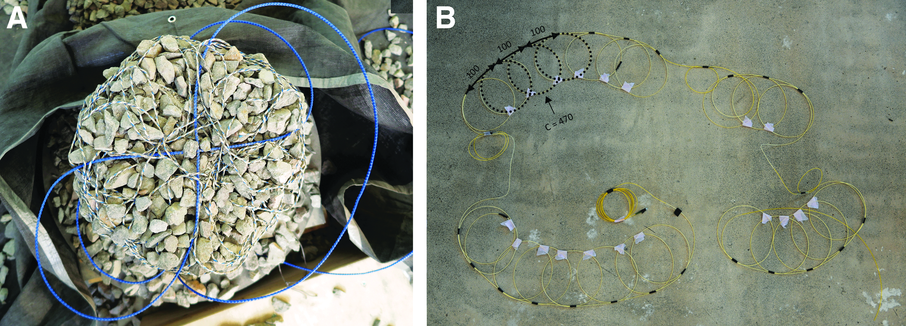
The string pattern, used for realization of our JAS, consists of circles as main units (Figs. 2 and 3). At an earlier stage of the project, other geometries, such as teardrop-shaped loops with different proportions, have also been empirically tested. Moreover, different string layouts have been studied using discrete element simulations. 13 However, the geometry of the circle proved to be most suitable and efficient for fabricating prototypes at a large scale. The equally enclosed circular shape defines the ability of the string reinforcement to evenly distribute the forces inside the structures and, at the same time, to confine and keep in place the bulk material on the surface. Therefore, the chosen size of the circle unit (Ø 150 mm) and the vertical distance between the individual horizontal layers (10 mm) depend strongly on the average stone size (16–32 mm) and the string thickness (2.5 mm).

Close view on the end effector attached to the robotic arm showing the individual steps of the fabrication process:
To computationally design JAS and to automatically generate string patterns for each of the horizontal layers of a desired shape based on the above-defined material settings, a computational design tool was implemented. The tool is written in Python and runs in the computational design toolkit Rhinoceros 3D/Grasshopper.
14
The procedure to generate the string patterns can be described as follows. First, an NURBS polysurface has to be defined as geometrical design input. It is sliced into horizontal boundary curves according to the defined vertical distance between the layers. These boundary curves are allowed to have a certain maximum curvature (
The string pattern on the boundary confines the stones on the surface and is responsible for the global shape appearance and surface definition of the structures. Thus, it is defined by the relationship between the circles, not only in the particular layer they are contouring but also in regard to the circles' position in the neighboring layers (Fig. 4). If the patterns do not correlate with each other, stones would erode through the gaps during the fabrication process. Each boundary curve is divided based on the optimal distance between the center points of the circles, informed by the findings of the uniaxial compression tests (see the Results section).

For the generation of the pattern in the structure's core, the computational tool distributes circles also inside each boundary curve by calculating a grid, which intersection points mark the locations for the circular pattern loops. In this way, an equal distribution of the circular units at the core of the structures is achieved. This is a requirement that is defined by the findings from the fiber-optic measurements presented in the Results section of the article. The generated string patterns serve as input for the fabrication process and define the robot's paths.
Fabrication method
The fabrication method, developed for the realization of our JAS, is similar to layer-based 3D printing methods in which the stones and string are placed in alternating layers using an industrial robotic arm with a customized end effector (see “Direct Deposition of Jammed Architectural Structures”—an article by Aejmelaeus-Lindström et al., accepted for the ROB|ARCH 2018 conference). First, the robot lays string, following the geometrically defined paths (Fig. 3A), and then deposits stones (Fig. 3B). After material placement, the top surface is compacted with a pneumatic hammer to increase the gravel density, to flatten the surface, as well as to activate the string reinforcement (Fig. 3C). This fabrication method allows for layer-based fabrication of the structures without any external confinement or formwork. Our JAS are conceptualized as in situ fabricated structures, since the absence of any permanent bonding between the two components of the material system makes their transportation and, therefore, their prefabrication precarious. The string is laid as one continuous piece throughout the prototypes and could therefore be easily pulled out to disassemble them. In this way, the structures can be fully recycled and brought back to the previous state of the material system's components; a pile of stones and a spool of string.
Material samples
The fabrication method was used to build multiple cylindrical prototypes (V = ca. 0.27
Due to the binding action of the string, the samples' dimensions were designed according to the testing procedure for uniaxial compression tests for cohesive soils in the ASTM D2166, 15 with the diameter being more than 10 times the largest particle size and with a height-to-diameter ratio between 2 and 2.5. The columns for the uniaxial compression tests were constructed with identical string patterns, but different string volume fractions of 4.6% (called HD) and 4.1% (called LD) for five samples each. The length of the string per layer was 10 m for the HD samples and 9 m for the LD samples, respectively. An additional LD column was prepared with embedded sensors to test the fiber-optic measurement technique, described later in this article.
Uniaxial compression tests
To determine the performance of the string-reinforced granular packing, unconfined compression tests were performed on the above-described samples with the compression direction perpendicular to the string placement planes. The aim was to quantify the unconfined compressive strength σu, the compaction behavior, as well as to estimate the relaxation behavior for samples. The prepared cylindrical samples were aligned to the center in between two compression plates of a servo-hydraulic universal testing machine (Schenck 480 kN). The compression plates were restrained to allow only for displacement in the vertical direction without rotation.
The applied constant displacement rate was 0.625%/min, while the unloading rate was 1.25%/min. The samples were incrementally loaded up to 40, 80, 120, and 200 kN, but once they reached the increment load, the displacement was kept constant and the sample was allowed to relax for 400 s. Consecutively, samples were unloaded to 6 kN and reloaded to the next load increment. This sequence was repeated until the maximum load of the samples was reached. Some of the samples were allowed to relax for 3600 s to study the material behavior under compression over a longer period of time. During the tests, the crosshead travel, as well as the force, was recorded at 1 Hz, and images of the sample were taken at 30 s intervals to analyze the surface behavior of the structures. To measure the deformation inside the structures during loading, embedded strain sensors have been applied, as discussed next.
Fiber-optic measurement tests
Fiber-optic measurements, based on Rayleigh backscatter technology, were performed to assess the deformation inside one loaded sample. Typically, in the field of engineering, such measuring systems are used for monitoring the structural health of bridges and concrete structures 16 by assessing the deformation of the reinforcement bars inside them. The measurements represent the assessed strain along the sensor‘s length. In the scope of our JAS project, the technology is used to analyze the deformation of a rather untested material system, string-reinforced granular matter, the performance of which differs significantly from the material behavior of continuous materials. Two types of fiber sensors were installed inside the prototype, one for assessing the general behavior of the structure and the other for measuring the local perturbations of the individual string pattern loops. The first type was a custom-produced glass fiber coated with a layer of metal and a layer of plastic thereon (Ø 5 mm). Due to the stiffness of the coating, these sensors cannot mimic the string placement. Therefore, they were placed straight inside the structures (Fig. 5A) and were used to capture the general behavior under the applied load. The second type of sensors was standard telecom cables with an inner core of 0.009 mm and total diameter of 0.25 mm. They, unlike the steel-coated ones, are more flexible and can take the shape of the string pattern (Fig. 5B). To protect the glass fibers from the sharp stone edges, they were placed inside a silicone tube (Ø 0.3 mm).
Two different types of sensors:
To perform fiber-optic measurements on one of the LD testing samples, a custom-made clamping setup was constructed to apply and measure compression on the sample. The setup consisted of two steel plates, one on top and one at the bottom, connected with threaded bars, a load cell, and a digital weight transmitter (Fig. 6). The nuts on the bottom were welded onto the steel plate, such that the threaded bars can be fixed in place after building a material sample directly onto the bottom plate. The top steel plate had holes, so the threaded bars can slide through and the plate can slide down by tightening the three nuts on the top. As such, the material sample could be compressed and became more resistant to external horizontal forces and vibrations.

Setup for the fiber-optic measurements consisting of
In the test, the structure was vertically loaded with a force of ca. 40 kN by tightening the top nuts and the applied force was measured with the load cell, mounted between the upper steel plate and the sample. In this loaded state, the sensor values of each sensor were recorded and their differences to the sensor's baseline were calculated. The results measured with the fiber-optic device are trustworthy up to a threshold strain value of 13,000 microstrain, and the maximum length of the sensor is limited to 50 m.
Since the measurements did not include the shape and position of the sensors in space, but only the strain along the sensor's length, a strategy was developed to map the extracted data onto a section curve in the digital model of the material sample, representing the sensors' placement (Fig. 7). For instance, in the case of placing the second sensor type as the string pattern, the aim was to measure the deformation of the individual circular loops, and hence, the sensor's segments that serve as a connection between these loops are not of interest. Therefore, the preparation of the sensors included to allocate the segments that form the loops, equal to the circumference of the basic circle unit
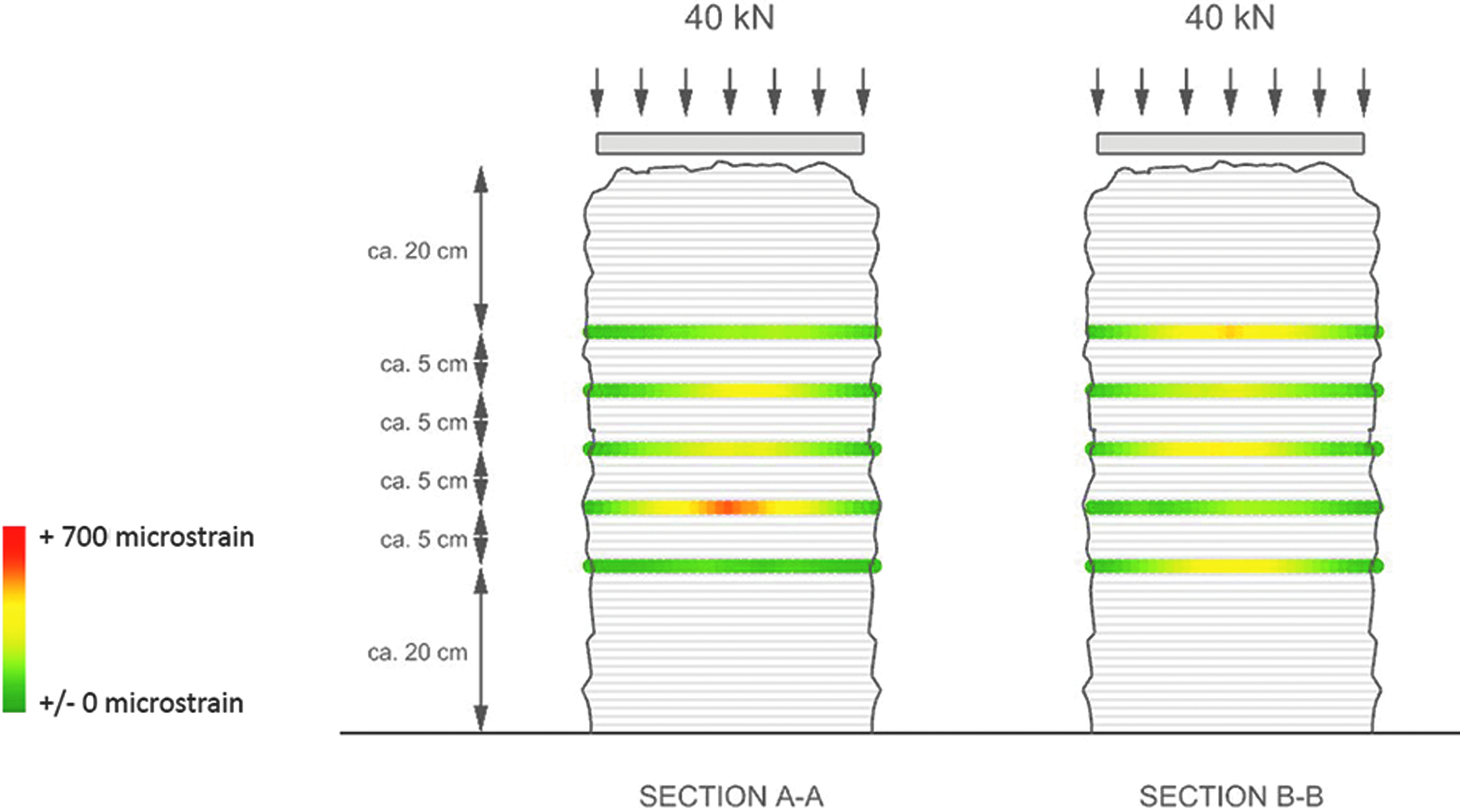
The results of the first fiber-optic measurement displayed by colors.
However, in the field of engineering, fiber-optic measurements are typically performed on significantly larger samples, so local disorder becomes irrelevant for the overall outcome of the experiment. In addition, multiple measurements are taken in equally spread periods of time to draw conclusions about the long-term behavior of tested structures. This was taken into consideration in the planning and execution of the following experiment.
Load-bearing capacity and deformation of a large-scale prototype
To test the load-bearing capacity and deformation of our material system at an architectural scale, a large-scale wall segment (Fig. 1) was fabricated. The size was defined through maximum dimensions possible with the available robotic setup (W = 1700 mm, D = 1000 mm, H = 2700 mm). Previous material tests proved that shapes with rounded horizontal sections are more suitable geometries, since, due to the overall stochastic behavior of the material system, sharp defined edges and corners are not feasible. Therefore, the minimum outer curvature radius for this prototype was derived from earlier material tests on the material resolution (see the Material Samples section - R > 330 mm). The structure was designed to be symmetrical and slightly curved through the middle, forming a wide v-shaped footprint. In this way, the possibility for buckling during the load test was minimized and a more stable global behavior was assumed.
The structure was wider at the bottom and, following a moderately curved B-spline, tapered toward the top. The top surface was dimensioned to fit the size of the prefabricated concrete slabs (W = 1900 mm, D = 900 mm, H = 190 mm), so that they can rest safely, and to allow for a slight cantilever. The structure encompassed a volume of ca. 2

The position of the concrete plates on the same axis as the center of mass of the wall segment was crucial for the success of the experiment. Due to the required height and due to safety measurements, the experiment took place outdoors beneath an 8 m high canopy. The load package was hung on a chain attached to a steel beam in the ceiling. In between the chain and concrete slabs, a scale was attached to measure the load placed on top of the structure. The placement was guided with two forklifts—one on the long side and one on the short side of the wall segment. In this way, it was possible to gradually compress the structure first with 10 kN, then with 18 kN, and finally with the full capacity—25 kN. This stepwise loading was intentional, since after each loading cycle, a fiber-optic measurement for assessing the structure's deformation was taken. The concrete slabs were left to rest on top of the structure for 20 days in total and two additional fiber-optic measurements were taken during this period.
Results
On the load-bearing capacity of our JAS
The performed uniaxial compression tests yield the first findings about the load-bearing capacities of our JAS material system and discuss the stone-to-string ratio of the material system. Although the difference in string density between the LD and HD samples (see the Uniaxial Compression Tests section) could be considered minimal, one can observe quite distinct behavior during loading in an unconfined compression test. Figure 10 shows the measured compressive stress/strain curves for two different string density samples. It is evident that samples with a higher string density exhibit stiffer macroscopic behavior with significantly reduced lateral strain. For HD samples, an average tangent stiffness in the region ranging from 10% to 85% of the ultimate stress is measured as 10.68 ± 0.13 MPa, while the LD configuration has 10.04 ± 0.30 MPa. Values for the Poisson's ratio are estimated to be 0.44 ± 0.02 for HD and 0.47 ± 0.02 for LD samples.
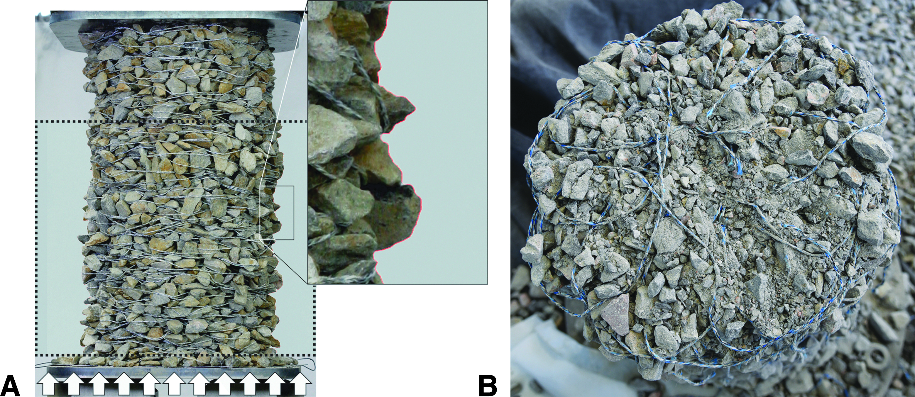
In addition, a series of images, recorded during the tests, were enhanced and segmented, allowing the contour to be analyzed (Fig. 10A), using the image processing toolbox MATLAB. The average horizontal position of the central part of the left and right contour was determined and used for the calculation of an average lateral and volumetric strain for all loading, unloading, and reloading paths. Note that even though subpixel accuracy is achieved, this method cannot be applied for final loading states, because if particles erode or shear bands form, single average values become meaningless. The volumetric strain is larger with more string. Due to high strain values, volumetric strains must be calculated without the typical neglect of terms with strain products.
The mean ultimate compressive stress σu is 1.95 ± 0.05 MPa for the HD and 2.29 ± 0.05 MPa for the LD configurations with respective strains of ɛu of −22.9% ± 1.3% for the HD and −28.2% ± 1.0% for the LD. To understand this counterintuitive behavior, it is important to investigate the failure evolution. By studying some of the samples after load tests, it became clear that a force of 200 kN causes significant failure of both—the stones and string in the middle area of structures (Fig. 10B). For both configurations up to σu, the samples compress uniformly with moderate barrel formation due to friction on the supports. The softening of the HD sample is dominated by the formation of a single shear band under 45 degrees, while for LD samples, disintegration within a larger horizontally oriented zone can be observed.
The incremental loading allowed to investigate how the system withstood the load. During unloading, first, a very steep descent can be observed, followed by a regimen with a strong decrease of stiffness (Fig. 11). This can be explained by the relaxing contact force network of the particles in the beginning, which is followed by string relaxation. If unloaded entirely, the unloading curve becomes almost asymptotic to the horizontal axis. The remaining plastic strain is a combination of grain attrition, fragmentation, and ratcheting. To quantify the plastic strain ɛpl, however, a line is fitted to the linear part of the reloading curve and its intersection with the strain axis is taken (see, for example, Fig. 11 gray line and * mark). The resulting true stress σT, plastic strain ɛpl normalized by total strain plot to decompose elastic and plastic strains, distinguishes the different behaviors of HD and LD samples (Fig. 12A).
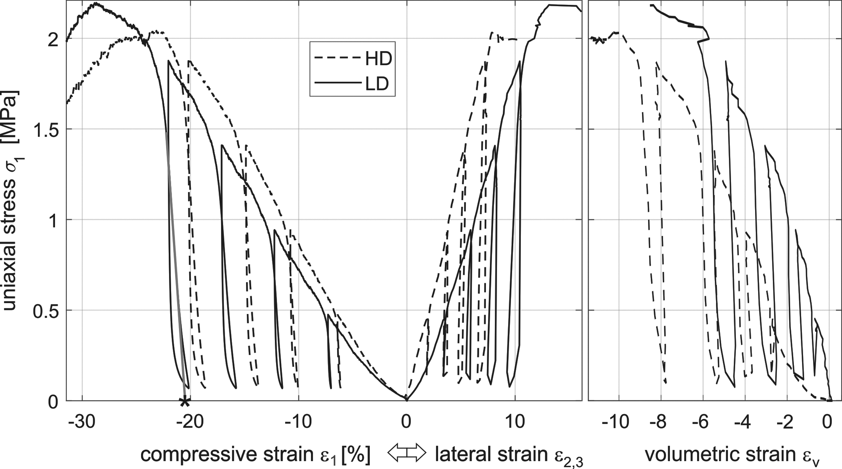
Typical nominal stress/strain plot for incremental unconfined compression test for one HD and one LD sample with average principal strain components and volumetric strain; the * marks the intersection between a line fitted to the linear part of the reloading curve and the strain axis.
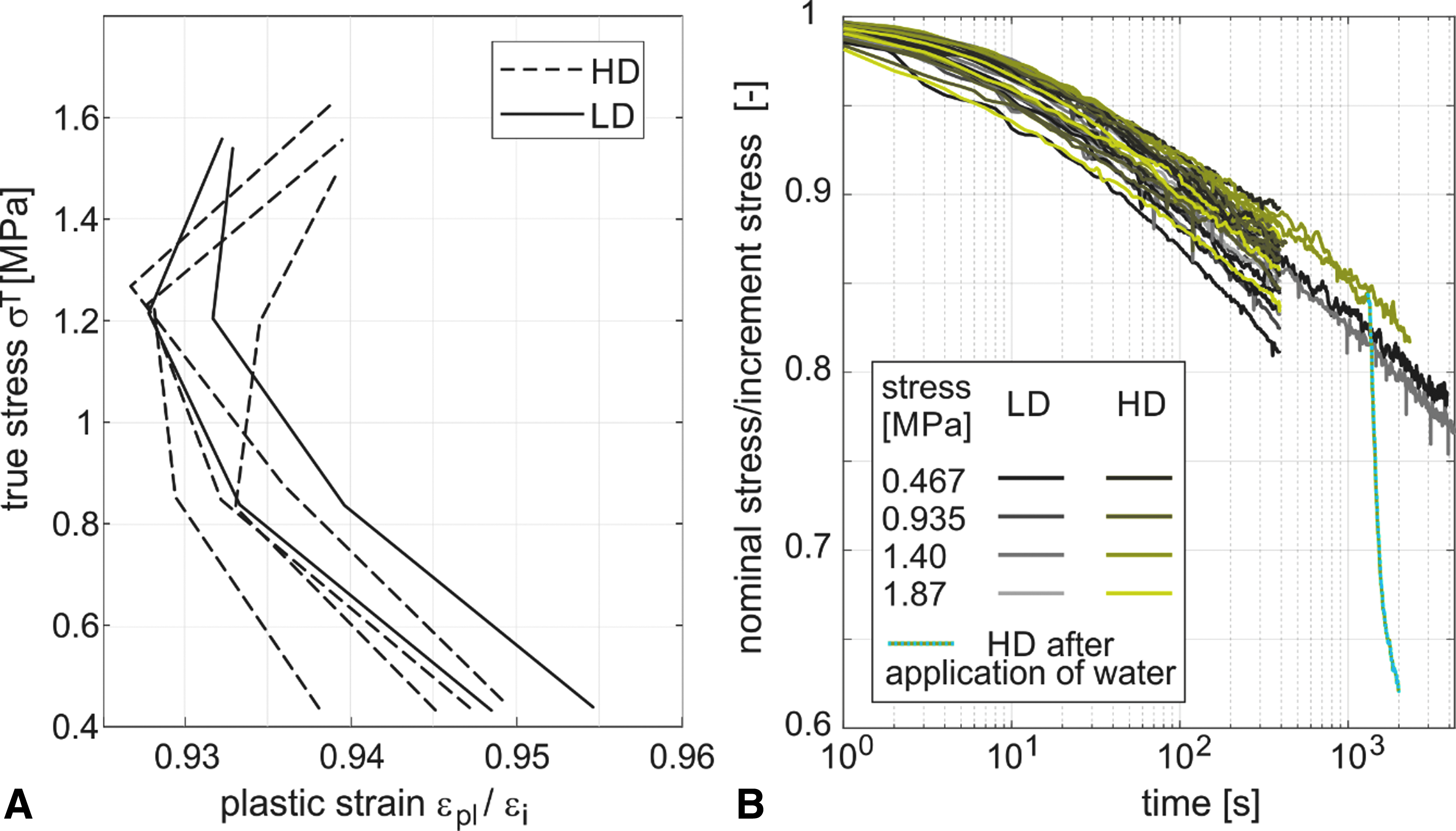
While HD samples initially flow less than LD samples, they exhibit significantly larger plastic strain increments when approaching the ultimate load. This could be the emergence of the early shear band localization. LD samples exhibit linear hardening up to the last stable increment. Note that the true stress calculated from the image correlated average lateral strain at that point is used (Fig. 12A), while other measures use the nominal stress that corresponds to the initial cross section. To summarize, the string impedes lateral expansion and thus for HD samples, the same axial displacement results in larger volumetric compression, enhanced stiffness, a lower Poisson's ratio, and increased plastic deformation in contrast to the LD case.
The relaxation curves for the loaded samples are shown in Figure 12B, with the nominal stress normalized by the initial stress at the beginning of the relaxation step. The rheonomous behavior of HD and LD samples is quite similar, with a trend of larger relaxation at higher load increments of HD samples. Note that the slope of the relaxation curves after 400 s is already close to the ones of 3600 s. Water was sprayed onto one HD sample 1000 s after reaching the third load increment, resulting in significant relaxation. This is critical for outdoor construction of JAS and has to be further investigated, as mentioned in the Discussion.
Unconfined compression tests, typically proposed for cohesive systems, are suitable to assess the behavior of string-reinforced granular matter up to the ultimate stress and beyond. Even though the string density of HD and LD samples does not differ strongly, the systems respond to compressive loading perpendicular to the string placement plane in distinct ways. The tested load is significantly higher than the typical loading of railway ballast, which causes particle attrition and fracture, resulting in compaction (ɛv < 0) and global reorganization of the intrinsic contact force network. With less string, the stones' tendency to rearrange is larger than for higher string density and all observed phenomena are a direct consequence of this relationship. As an example, HD samples are stiffer (Fig. 11) and less compact, and exhibit less volumetric compaction strain and smaller plastic strain increments. Hence, they are more prone to localization in form of shear band formation resulting in smaller ultimate strain (Fig. 10) and reduced plastic hardening (Fig. 12A). In conclusion, the LD samples demonstrated a more resistant behavior during the load experiments. Hence, all following prototypes built after these test series were based on the pattern density used for LD samples. This finding is of great importance for the string pattern distribution logic of our JAS (see the String Layout section).
On the deformation of our JAS
The results from the fiber-optic measurements provide information about the material deformation inside the structures. The results illustrated in Figure 7 show the two sections of the sample along the horizontal axes (Fig. 5A) with the measured data mapped on the segments inside the structure. The colors represent deformation of the sensor after applying vertical force and range from green to red, where red indicates positive strain. The mapped data show local disorder. For example, the red segment displayed on section A-A probably identifies a sharp stone edge pressing strongly on the sensor.
In addition, the completely green area on the same section is the last segment of the sensor, where the measurement's accuracy depends strongly on how well the glass fiber's end is protected from light absorption. It is evident that the most deviation occurs at the core of the column, which matches the preliminary assumption that the forces concentrate in the middle of the structure. The same conclusion was drawn during one of the uniaxial compression tests, described earlier. During this experiment, 200 kN force was applied on top of the sample resulting in string breakage only in the middle area of the structure (Fig. 10B).
With the performed tests, it became explicit that the internal string arrangement is of great importance for the distribution of forces occurring at the core of our vertically loaded JAS. Therefore, the string circles in the middle area of each layer should be positioned as equally as possible to each other. In this way, the perpendicularly applied forces can be evenly distributed through the structure's core. This finding is integrated into the string pattern generation logic, described earlier in the article (see the String Layout section).
Results from the large-scale experiment
To test the developed string distribution and load-bearing capacity of the material system at an architectural scale, a wall segment was fabricated and loaded with concrete slab (see the Load-Bearing Capacity and Deformation of a Large-Scale Prototype section). The applied force resulted in 0.05 MPa, or 40 times less than the maximum compression force applied during the uniaxial compression tests, described earlier. However, the structure withstood slightly more than its self-weight, through which neither the string nor the stones broke during the experiment. This proves the concept of our load-bearing and, simultaneously, fully reversible JAS.
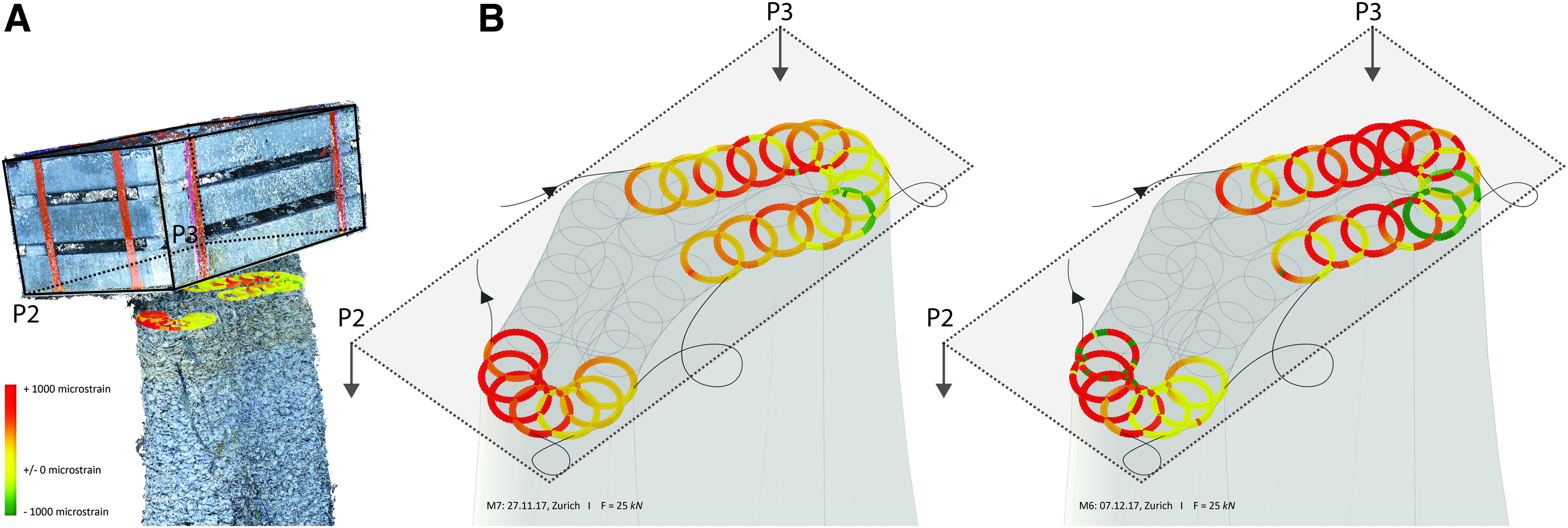
The concrete slabs were not placed completely horizontally on top of the wall segment because of the uneven surface of the structure, as well as the difficult estimation of the final volume of the wall segment and its exact position in relation to the hanging load package. The wall segment was loaded unevenly, pressing more strongly through corners P2 and P3, respectively (Fig. 8A). This predefined the deformation direction of the structure and its final tilting. This was also visible through measurements along the sensors. The results of the steel-coated sensor (Fig. 8A) show the positive stain deviation marked in red and the negative strain deviation marked in green. According to all measurements, a constant deformation, caused by both compression and tension of the sensor, occurred on layer four. This might be due to constant rearrangement of matter over time, resulting in both pulling and pushing of the glass fiber. In addition, since the first day of the experiment, deformation was measured around the center point of layer two under the force of 25 kN (Fig. 8[A-M7]) and gradually increased in the following 20 days (Fig. 8 [A-M8;M9]). Figure 8B represents a point cloud created from multiple pictures taken on the last day of the load experiment and imported to standard photogrammetry software. A more precise mapping of the sensor data was possible based on a comparison between the designed sensor position and point cloud. Since the largest positive strain deviation occurs on layer two, and this is approximately the level at which the structure starts bending, the sensor measurements match the general tilting of the prototype.
Furthermore, the results of the measurements taken by the silicone-coated sensor also correlate with the general deformation of the structure (Fig. 9). The parts mostly colored in red are below corners P2 and P3 of the concrete slab, which, due to eccentric loading, press more on the structure. The two subsequent measurements show a gradually amplified deformation in the regions mainly affected by the uneven impact of concrete slabs on the structure.
Despite imprecise loading, the experiment was still successful since the wall segment did not collapse and the results of the fiber-optic measurements related to the general deformation of the test sample. Therefore, the validity of the method to allocate and quantify the deformation of string-reinforced granular matter was proven.
Conclusion
The marginal stability of granular matter, described in the beginning of the article, can be overcome by, on one hand, adding textile reinforcement and, on the other hand, additionally applying compression force on the jammed structures. The article presented here describes first steps into defining the performance of string-reinforced granular matter and its potential of becoming an actual building material. Two methods were applied to collect findings about the material and have been validated through the uniaxial compression tests, the fiber-optic measurement tests, and the large-scale experiment.
The results reveal a definite link between string content and placement and the structural behavior of our JAS. Consequently, it was proven that the string pattern has not only a confining function but also a direct influence on material behavior. The large-scale experiment (Fig. 1) demonstrated the potential of the fiber-optic measuring technique for long-term monitoring of structures composed of loose stones and string. Moreover, the large-scale loaded wall showed the capacity of our JAS to perform as load-bearing building component. The findings from the material tests have been incorporated into generative logic for string layout, which is fundamental for the design and fabrication of material-aware JAS.
Discussion
The results of the experiments, described within the scope of this article, yield two topics for further investigation: on one hand, the material behavior and, on the other hand, the architectural potentials of our JAS. Regarding the material properties, an important feature of the material performance, discovered during the uniaxial compression tests, is the creep that occurred due to the polymeric string, the string-grain, and intergrain contacts. It exhibits a time-dependent behavior that is amplified with the presence of moisture. If building JAS under outdoor conditions, the deformations caused by the impact of rain or condensation have to be considered. Furthermore, the experiments described within this article focus on the application of vertical compression force only. The behavior of JAS exposed to both vertical and horizontal forces could be interesting for further exploration, under the assumption that the structures become even more stable if compressed.
In the context of architectural design, the function of the presented computational tool could be extended from the generation of material-informed string layouts based on input geometries to the algorithmically controlled formation of structurally sound and fabrication-aware JAS. In addition, an arrangement of multiple JAS walls could result in more stable behavior under the weight of a slab and compensate for an imprecise placement. Moreover, since the compression force applied on the wall segment, Figure 1, was more than its self-weight, two-story JAS could be a further step in testing the architectural potential of our material system.
Footnotes
Acknowledgments
The research is sponsored by the ETH Zurich Foundation. The authors thank the team at ETH Zurich for the collective efforts in building the prototypes described in this article, especially Dr. Ammar Mirjan, Stephané de Weck, Marco Palma, Jesús Medina Ibáñez, Michael Lyrenmann, and Philippe Fleischmann. They are particularly grateful to the team at ETH Zurich HIF-Bauhalle, and especially to Dominik Werne, for the opportunity to use the necessary machines and equipment for the conducted experiments. In addition, they are grateful to the group of Prof. Walter Kaufmann “Concrete Structures and Bridge Design” (Department of Civil, Environmental and Geomatic Engineering, ETH Zurich) and especially to Severin Haefliger, for sharing their experience with the fiber-optic measuring device. Finally, the authors thank Dr. Romana Rust for the fruitful discussions and her valuable insights.
Author Disclosure Statement
No competing financial interests exist.