
Abstract
Additive manufacturing (AM) is gaining increasing interests in modern industries, with its unparalleled capability for direct manufacture of high-value geometrically complex products. With continued technology advancements, plastic AM enables consumer goods to be economically produced in a low to medium production scale. Due to unique AM process characteristics, current design methods that are established based on traditional manufacturing processes are unable to effectively capitalize AM advantages. The traditional designer's mind-set in product design needs changing, which requires new design methods and guidance to be established. However, the majority of the design rules for AM developed so far is primarily on “feature-level,” namely, they can only ensure the manufacturability of the designed features in the final design stage. This fails to guide designers throughout the entire design process to exploit full potentials of AM processes. Therefore, this study proposes a design for AM (DfAM) framework to guide industrial/product designers to create an effective design for end-use plastic consumer products for series production. The framework is developed based on a practically proven design practice that is obtained from a series of interviews with professional designers and practitioners with significant experience in DfAM. It summarizes the DfAM principles and addresses major considerations in process selection, design process, and production. This article focuses on illustrating the framework using two detailed case studies showing the real design process for designing two products that are currently being sold on the market. The DfAM principles and considerations in manufacturing process selection, design, and production stages are presented, together with the advantages and disadvantages of the products being designed for AM. It demonstrates the importance of DfAM principles for creating a successful product design.
Introduction
The emergence of additive manufacturing (AM) is changing the way that products are designed and manufactured. The application of AM has expanded to a wider spectrum, including not only aerospace and medical applications but also daily consumer goods market. 1 The layer-by-layer fabrication characteristics distinguish AM from traditional production processes. As a result, the concept of design for AM (DfAM) has emerged, which aims to help designers capitalize advantages of AM while circumventing the inherent limitations, maximizing product performance and reducing production costs.2,3
The majority of the research relating to DfAM design guidelines and rules is on the feature-level, investigating the limit of a specific AM process capability in relation to achievable part quality, for example, minimum wall thickness producible by selective laser melting (SLM) 4 and self-supporting angle for fused deposition modeling (FDM).5,6 Allison et al. 7 developed design rules that detail the achievable geometric resolution and accuracy in relation to build orientation, materials, and locations within the build chamber of the selective laser sintering (SLS) system. Kranz et al. 8 developed extensive SLM design rules, showing the dimensional accuracy and surface quality of a range of typical features (e.g., holes, cylinders, and thin walls) in relation to build orientation. In addition to SLM, Adam and Zimmer9,10 established SLS and FDM rules for similar features. Similarly, Lockett et al. 11 evaluated the process capability of wire arc AM, by which a set of design rules in terms of geometrical complexity and symmetry were complied. More design rules can be found in the recent review articles by Kumke et al. 12 and Yang and Zhao. 13 In addition to academic research, industries are also keen on developing design guidelines and rules. Leading AM manufacturers (e.g., Stratasys, Inc., 14 EOS GmbH, 15 and 3D Systems, Inc., 16 ), software developers (e.g., Materialise NV 17 ), and service providers (e.g., 3D Hubs 18 ) have established a comprehensive set of “feature-level” design rules, covering a range of mainstream AM processes.
In addition to feature-level detail design rules, AM-enabled lightweight designs are becoming an increasingly popular research topic. Lightweight design is usually realized by applying advanced computer algorithms such as topology optimization (TO), 19 cellular structures, 20 and biologically inspired optimization. 21 Belhabib and Guessasma 22 developed a TO-based asymptote method for minimizing part volume by up to 50%. Garland and Fadel 23 combined TO with the orthotropic gradient material optimization method to optimize the macroscopic structure of a part. Syam et al. 24 proposed a method for cellular structure generation, which takes into consideration, part volume, material properties, and mechanic vibration resistance. Yang et al. 25 redesigned a triple clamp by combining a number of components into one, followed by generating cellular structures for weight reduction. With respect to biologically inspired optimization methods, Dhokia et al. 26 developed a generative design tool utilizing the behavior of termites in constructing complex nests to optimize AM parts.
High-level design methods have also been investigated to facilitate the design process. Rias et al. 27 built an open framework upon the concept of intermediate objects to assist concept generation for AM. Panesar et al. 28 developed a design framework to assist designing products with embedded components. Orquéra et al. 29 developed an optimization approach to designing and optimizing movable engineering components for mechanical systems.
While substantial effect has been made to advance DfAM research in recent years, most of the studies focus on the design of engineering components for engineering applications rather than the design of daily consumer products from an industrial/product designer's perspective. The “feature-level” design rules can only be used to assess the printability of an already designed feature. They fail to help designers exploit full potentials of AM processes. Although TO capitalizes certain AM potentials and capabilities, it cannot stimulate designers to conceive the product in early design stages, so that misses the opportunity to take advantage of full AM potentials. Therefore, this study aims to develop a holistic DfAM framework based on design practice adopted by professional industrial and product designers. It provides guidance throughout the entire design process for designing end-use plastic consumer products for series production, allowing designers to utilize AM advantages and circumvent the disadvantages. This article is focused on demonstrating the major elements of the framework using two detailed case studies. The research methodology used in this study is presented in the Research Methodology section. The overview of the framework is described in The DfAM Framework section, followed by the case studies of two successful products in the Case Studies section.
Research Methodology
An interview-based research method
30
was used to collect data for developing the DfAM framework. This study consisted of three stages as follows:
First stage: the professional designers were first sought through the partners of this research project. A short survey was then conducted to understand designers' general experience in plastic AM, helping to identify more informants. Finally, a list of 17 interviewees was formed. All of the designers have had significant experience in DfAM together with long-term exposure to product and engineering design from 5 to 20 years with at least a Bachelor degree in industrial/product/engineering design. Second stage: the first 11 designers and AM practitioners were interviewed and the initial framework was developed. Third stage: two case studies were performed where six designers and practitioners from two companies were interviewed. These two cases were selected as the two products were currently sold on the market. They were designed specifically for series production using SLS and FDM, respectively. The designs were investigated in-depth to refine the initial DfAM framework.
In total, 13 structured on-site interviews (including group interviews) were conducted. The successful products that were available on the market (at the time of the interviews taking place) were discussed. Three mainstream plastic AM processes are considered, namely, SLS, stereolithography (SLA), and FDM.
The duration for each interview was 150–180 min consisting of three major sections in sequence: (1) understanding the participant(s)’ overall experience in DfAM; (2) analyzing example plastic parts/products, for example, process selection between AM and traditional production processes, and pros and cons of using AM; and (3) exploring the impact of introducing plastic AM into the current design and production of consumer goods.
The interviews were audio recorded and transcribed into more than 190,000 words of text-based data, which was then divided into groups for analysis using QSR NVivo 11® software. The passages of interest were thematically tagged and related to each other. 31 The data were analyzed by three researchers independently. The early form of the DfAM framework was developed based upon the first 11 interviews, which was then presented to the interviewees to gain their insights (i.e., the second stage of this study). Finally, additional two in-depth interviews (i.e., the 12th and 13th interviews in the third stage) were conducted, focusing on the design process of two consumer products presented in the Case Studies section. Based on these two interviews, the DfAM framework was refined, which is described in The DfAM Framework section. The research methodology presented above is depicted in Figure 1.
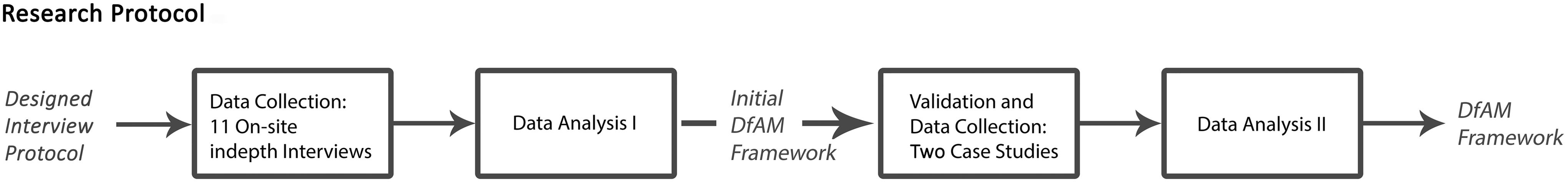
The research methodology. In total, 11 on-site interviews were conducted, following which two detailed case studies were performed investigating the design principles and rules for two successful consumer products currently sold on the market.
The DfAM Framework
The DfAM framework is depicted Figure 2, which is developed from the interviews based on real and successful products that were designed for plastic AM and manufactured in series production. The framework shows a typical design process for the development of a new end-use product for plastic AM volume production. In general, the first step is to select an economically viable and capable production process based on the product requirements. A number of factors come into play in the process selection, for example, material, production volume, lead-time, and costs. This requires the designer to acquire a broad understanding of various production processes such as process advantages, disadvantages, manufacturable geometries, and associated production costs.

The design for AM framework for designing end-use plastic consumer products. The main flow starts from design requirements, through selection of manufacturing processes, conceptual, embodiment, and detail design, to process planning analysis. Various considerations, design rules, and AM process limitations are considered throughout the entire design process. AM, additive manufacturing. Color images are available online.
If AM is chosen to be the production process, it does not mean the design is completely free of constraints. On the contrary, it requires the designer to consider unique AM process characteristics throughout the entire design process. AM-specific design rules and guidelines need to be followed. Having said that, AM does enable the designer to place more attention to pursuing design aesthetics and product functionality due to its capability to produce complex geometries. It was found from the interviews that, apart from design rules and guidelines, the design of a product is fundamentally restricted by production costs and also affected by the designer's own intents. It is also noted that these factors are not isolated and instead are interconnected. For example, the production cost has an impact on the designer's intent. The designer is restricted by the production costs, which reflects on the product appearance if the specific appearance will incur a high production cost. When the product design is finalized and progressed toward production, certain AM-specific production considerations should be carefully examined to facilitate the printing process and ensure finished products are of high and consistent quality.
Case Studies
Two case studies were carried out, exploring the designs of a night lamp for SLS and a moon-shaped lampshade for FDM. The first case study focused on the early and main stages of the design. The second case study looked into the later stages of the design process. The principal designers for these two products were interviewed (interviewee ID15 * for the night lamp case and interviewee ID16 and ID17 for the moon-shaped lampshade case). The DfAM framework was presented to the interviewees and the validity was assessed.
Case study I: design of a desk night lamp
Product overview
A desk night lamp made of Nylon 12 is shown in Figure 3a. The size is 82 × 72 × 93 mm (L × W × H). It was series produced by SLS. The total number of items produced at the time of writing this article was 500. For each SLS build, 60 lamps were produced. It was sold on the market as £18–20 each. The shape of the lamp is based on an already extinct bird—Raphus cucullatus, also called Dodo. It was sold as a souvenir in the exhibition of rare endangered animals hosted in the Shanghai Museum and London Natural History Museum. The lead-time of this souvenir design project was 4 months, including design and production.
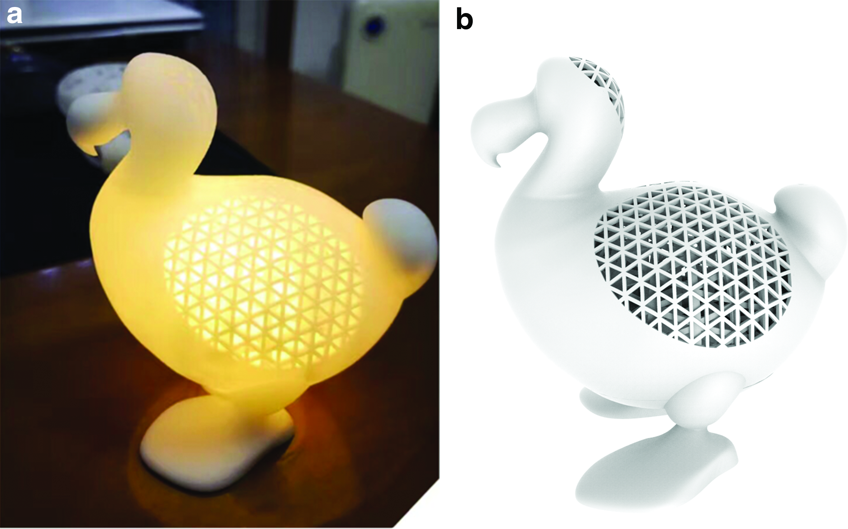
The desk Raphus cucullatus night lamp made by SLS
The lamp comprised three parts: (1) a lamp main body that contains a bulb, electronics (for brightness control and touch switch), and a battery chargeable through a standard USB socket; (2) a 1-mm-thick spherical bulb cover (Fig. 4) that sits inside of the main body to reduce the light intensity to avoid the bulb being exposed directly to customers; and (3) a cap at the bottom of the main body for placing and installing the bulb, electronics, and battery. The main body is hollow with various wall thicknesses throughout. The light is scattered through the hollow-out triangular structure, creating a luminous effect.

The plain view of the lamp (courtesy of Yunji Creative Design Ltd.). The bulb cover pointed by the arrow is designed to be contained within the lamp main body, which cannot be produced by traditional manufacturing processes. Color images are available online.
Production process selection
The traditional mass production technique that was first considered was blow molding. However, assembly operations and substantial additional costs would be needed to manufacture the hollow-out triangular structures that are embedded in the hollow main body. In addition, before the design process, the designer intended to design fine textures on the Dodo's head and the bulb cover to create a stylish layering luminous effect, which would be virtually impossible to produce by blow molding. Plastic AM processes were thus considered. As a customer-facing product, SLS and SLA were more suitable than FDM in terms of surface quality and smoothness. When it came to the comparison between SLA and SLS from the production perspective, SLS was a better option due to (1) a much higher production rate, that is, 60 lamps can be packed together and produced in one build, and (2) no need for support when printing the large hollow lamp main body.
Advantages and disadvantages of designing the lamp for SLS
Advantages
It allowed the designer to design the hollow main body of the lamp with freeform curves and texture at no additional cost, for example, the hollow-out triangles (Fig. 3), the beak (Fig. 3), and the texture on the bulb cover (Fig. 4). The bulb cover reduces brightness together with the texture that creates a scattered lighting effect, enhancing the product functionality. The functionality was further enhanced by designing various wall thicknesses in different regions of the lamp. For instance, the light intensity in Figure 3a is the strongest in the triangle area, reduced in the neck and thigh areas, and blocked in the beak, feet, and tail areas.
In addition, to ensure the lamp can firmly stand on the desk, the center of gravity was designed to be in a proper position, which was achieved by adjusting the weights of the beak, feet, and tail using varying wall thicknesses. It was not virtually impossible for blow molding where the wall thickness needed to be constant, leading to compromised product functionality and appearance.
Disadvantages
One of the drawbacks of the lamp being designed for SLS is the lack of consistent process repeatability in terms of dimensional accuracy in series production. Another major drawback is the low durability during the product lifecycle. The lamps tend to fade gradually after 12 months of use and will eventually become dark yellow, significantly affecting the product appearance.
“I once asked [an AM bureau] to make 60 pieces [the lamp] and they came out well. Perfect. But the next time I asked them to print 30 pieces, and they were all small, out of tolerances. For some cases, the head [the Dodo's head] being smaller wouldn't matter too much, but for some cases like the inlet, it's critical because I can't actually fit the bulb into the lamp, because it's too small. This also had something to do with the printer set up. So I had to make sure all parameters were set up correctly before I told them [the AM bureau] to hit the print button.” (interview ID15)
The design process
Conceptual, embodiment, and detail design stages
Conceptual design
The designer started with developing 3D computer-aided design (CAD) models based on a sketch of the R. cucullatus (as shown in Fig. 5a) provided by the British Museum, which formed the foundation of the conceptual design. Given children and teenagers being the target customers, the idea was to come up with an animated and lovable shape but also presented the actual appearance of the R. cucullatus.
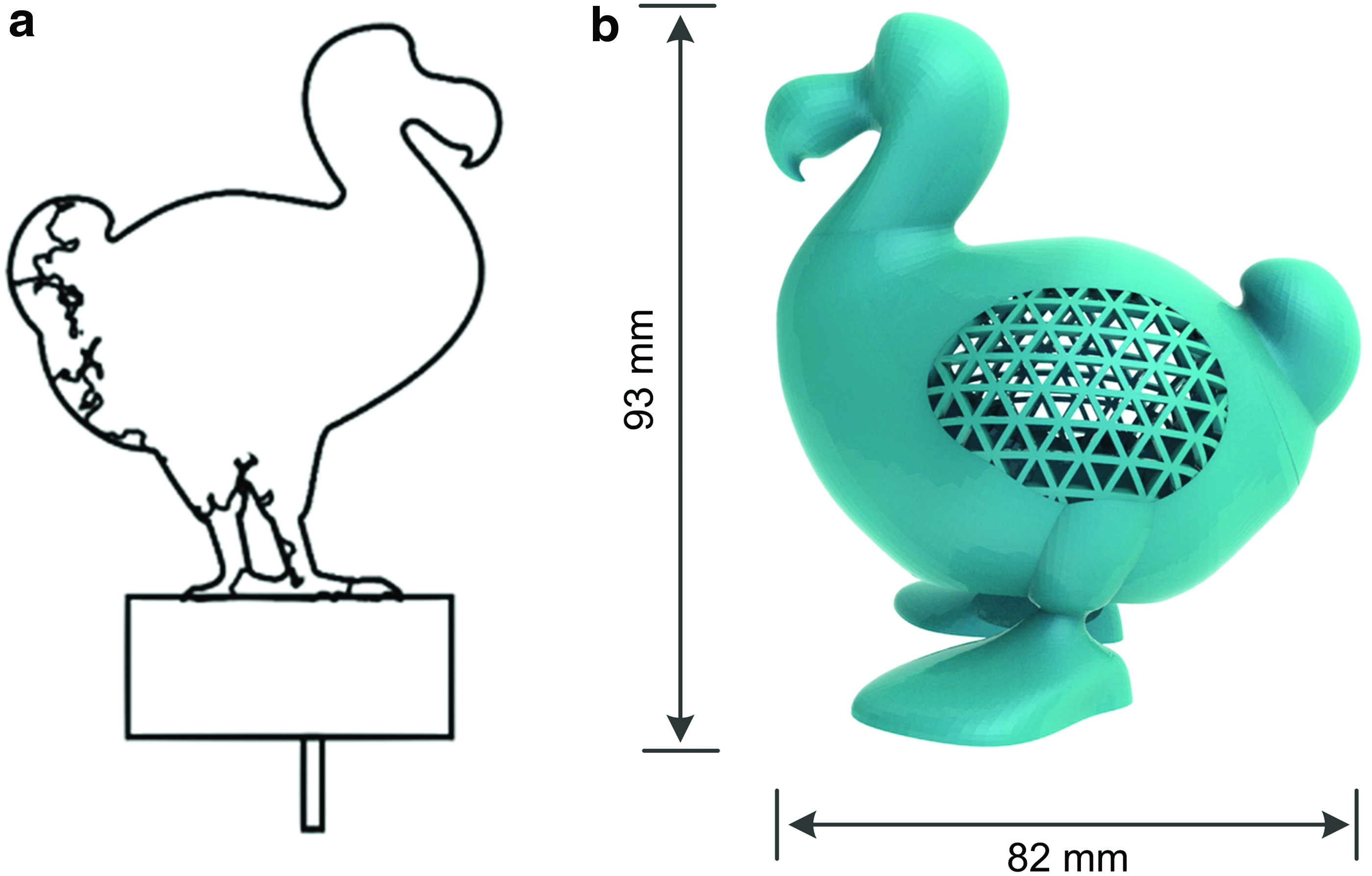
An early version of the lamp design (courtesy of Yunji Creative Design Ltd.)
Embodiment design
The wings of the R. cucullatus were first removed, creating the space for light dispersion, that is, the hollow-out triangles shown in Figure 5b. There were a few shape basic shapes to choose from for the hollow-out structures, including triangles, circles, diamonds, and random curves. Due to the Shanghai Museum having some triangles as the interior and exterior decoration, similar triangles were thus designed to embed into the lamp. A bulb cover with convex texture was also designed, generating soft lighting with a shaded effect when the light comes through the cover. As SLS typically processes Nylon 12 in the temperatures between 178°C and 180°C, the critical consideration in the bulb cover design was that it did not entrap much heat from the bulb. Otherwise it would cause not only the bulb overheat but also, as a consequence, degradation of the cover.
Detail design
In the detail design, dimensions of each feature were determined, for example, wall thickness of the tail, which were refined in the preproduction runs. Unsintered powder removal was considered to make sure it could be completely removed, particularly for sharp corners such as the beak and the feet.
Designer's intents and considerations
Design for product functionality
The functionality of the lamp was enhanced by designing the bulb cover and the hollow-out triangular structures. The bulb cover reduced the lamplight intensity to an extent that is comfortable to human's eyes. The texture on the cover together with the triangles, as described in the Conceptual, Embodiment, and Detail Design Stages section, created a better illumination effect.
Design for product appearance
As introduced in the Conceptual, Embodiment, and Detail Design Stages section, the adorable shape of the R. cucullatus lamp was designed in the conceptual design to attract interests from children and teenagers. As a souvenir, it originated from the morphological features of a real R. cucullatus (shown in Fig. 5a) but presented itself in a more pleasant way to the target customers. The design of the hollow-out triangles was also the designer's own preference. As such, the advantage of SLS in producing complex geometries was highlighted.
Design considerations in relation to postprocessing
A few modifications on the design were made to address some design considerations relating to postprocessing. Printing the beak and the feet that contained sharp corners could result in difficulty in removing unsintered powder. Hence, their shapes and dimensions were carefully determined. The struts between each hollow triangle were thickened and widened to make them sufficiently rigid to avoid potential damage in postprocessing, for example, high pressure bead blasting.
“It's [sic] not always possible for machine operators in [the AM bureau] to be very familiar with your designs, so sometimes in powder removal they might not pay enough attention, for example some tiny features or corners. We've found some of our SLS parts that aren't [sic] 100% clean. So I'd [sic] prefer to design something simple, that does not need too much sophisticated post-processing, so we can reduce uncertainties in finished part quality.” (interviewee ID15)
Case study II: design of a moon-shaped lampshade
Product overview
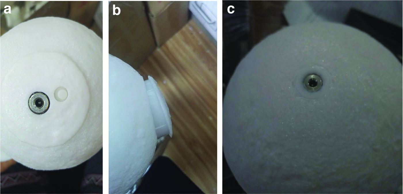
An example of the moon-shaped lampshade is shown in Figure 6, which is series produced by FDM. The company (i.e., Zeegine Ltd.) that designs and produces the lampshades also develops its own FDM systems. The series production is realized by having more than 100 FDM machines in parallel with each one printing one lampshade at a time, as showcased in Figure 7. The production rate for one FDM machine is two items per day. The material used is polylactic acid. This spherical lampshade has a shell thickness of 1.2 mm and a diameter of 150 mm. The bulb, rechargeable battery, electronic board, and touch switch are housed in the lampshade. Impressively, the entire lampshade is printed in one go without assembly. This is achieved by pausing the print halfway through the build, placing the bulb as well as other elements into the lampshade, and resuming the print until the lampshade is completely made. The convex texture (referred as “emboss” in this article) on the lampshade surface represents the landscape of the moon, with an average thickness of 2.5 mm. At the time of writing this article, there had been more than 3000 lampshades produced with a price of ∼£40.
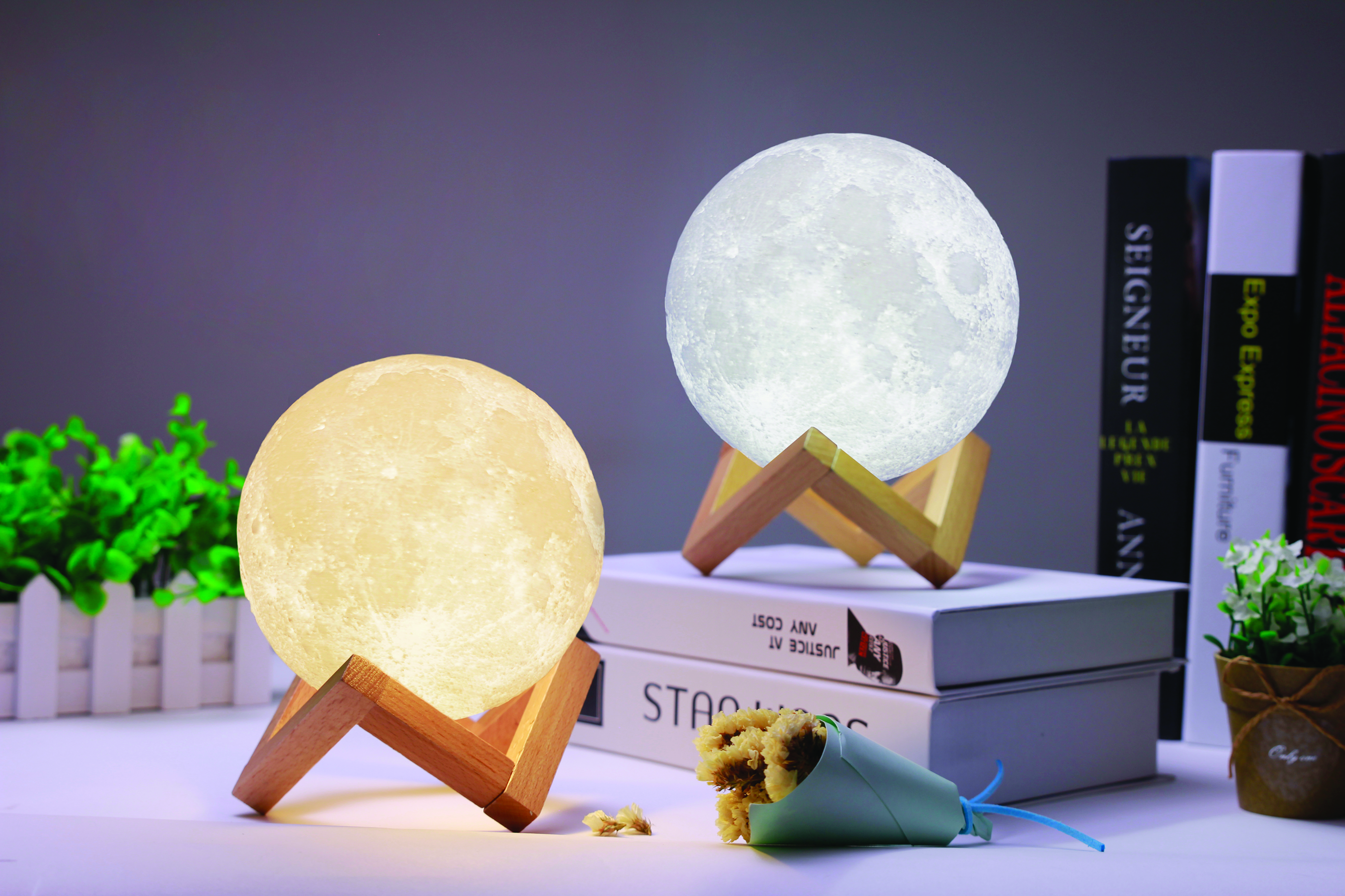
The 3D-printed moon-shaped lampshade made by FDM (courtesy of Zeegine Ltd.). The landscape of the moon is displayed while the lamp lights up. The bulb was placed into the main body half way through the build. FDM, fused deposition modeling. Color images are available online.

Series FDM production of moon-shaped lampshades (courtesy of Zeegine Ltd.). This shows the viability of using FDM in a series production scenario. Color images are available online.
Production process selection
As the lampshade was a plastic product, injection molding was first considered to be the production process. However, before designing the lampshade, the designers could not foresee how customers would respond to the product and thus were unsure of the production volume. Using injection molding for low-volume production would significantly increase the production costs. In addition, the lampshade would have been designed in at least two separate pieces for assembly if injection molding was used. On the contrary, injection molding allowed the lampshade to be designed and manufactured as a complete unit at a lower cost than injection molding. FDM also facilitated the iterative development of the product. The company has recently launched the third generation of lampshade to the market, which would not have been economically viable if injection molding was selected. Moreover, the texture of the lampshade was not dimensionally critical to customers, which also justified the use of the FDM process.
Advantages and disadvantages of designing the lampshade for FDM
In addition to the advantages mentioned above, the FDM process provided increased flexibility for the designers to control the transparency of the lampshade to the light by changing the emboss thickness in different regions across the entire lampshade. Figure 8 shows the top view of the lampshade. Figure 8a is the prototype under development and Figure 8b is the final product. Both spheres have the same landscape, but the emboss thickness was reduced in Figure 8b, allowing more light to penetrate through the lampshade creating a better illumination effect.

Top view of the lampshade with the light on (the red circle is the top of the sphere):
The disadvantages of using FDM included low-dimensional accuracy, increased cost for increased production volume, and low repeatability in finished product quality, which also resulted in a low yield (i.e., low rate of qualified products). At least 20% of the printed lampshades were categorized as unqualified. This was due to (1) an increased possibility of print failure in a long build (10 h per lampshade), and (2) unstable FDM systems developed by the company itself.
The design process
Conceptual, embodiment, and detail design stages
Conceptual and embodiment design
Since the lampshade design was purely based on the real landscape of the moon, the computer model of the lampshade was generated from a photograph of the moon in Figure 9a, using a specific design software (the interviewees preferred not to disclose the software name). The generated computer model is shown in Figure 12b. The thickness of the each emboss depends on the lightness † of each crater on the moon's photograph in Figure 9a. Another major task in the embodiment design was to design the lampshade as a single sphere instead of two hemispheres for assembly while making sure it could be successfully printed, which is presented in the Designer's Intents and Considerations section.

A photograph of a region of the moon
Detail design
The detail design stage involved continuous refinement of features to ensure manufacturability. The designers insisted not to use support structures as this would diminish surface quality. Therefore, the emboss thickness and inclination angle needed to be adjusted.
“We tweaked the design to make sure all embosses were self-supported. This was particularly important for the bottom of the lampshade where support was usually needed. [The original emboss is shown in Figure 10a and the tweaked one which was self-supported is shown Figure 10b].” (interviewee ID16)
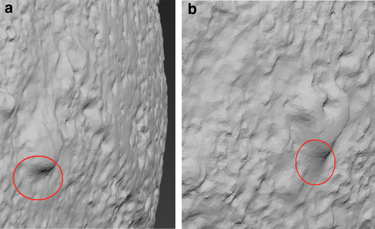
Tweaking the inclination angle of an emboss to ensure it supports itself in the FDM print (courtesy of Zeegine Ltd.). The inclination angle in the original design was shown in
Testing and design iterations
Four major design modifications were undertaken since the first version of the design. The most significant change was to design the lampshade in one complete unit for manufacture, which is shown in Figure 11 and described in the Design for Product Appearance section. In addition, more than hundreds of minor modifications have been made in the continuous embodiment, detail design, and iteration process. Some examples include tweaking emboss thickness to enhance the illumination effect (shown in Fig. 8) and adjusting the inclination angles of the embosses to ensure printability (shown in Fig. 10).
Lampshade design iterations.
Designer's intents and considerations
Design for product functionality
As presented in the Advantages and Disadvantages of Designing the Lampshade for FDM section and Figure 11, the thicknesses of some embosses were carefully adjusted, by which the lampshade provided a better illumination effect when the light was turned on.
“We've [sic] done perhaps over a hundred changes to embosses. Some of them were too thick so they became very dark when you switched the light on, so you can't [sic] really see them clearly. We didn't [sic] like that because that didn't [sic] show you the landscape of the moon. On the other hand, some embosses were too thin, so you can see this region is very bright [the interviewee was pointing at a lampshade prototype shown in Figure 8a]. ‘Cause it's [sic] too bright, it'll [sic] make you uncomfortable if you are very close to it.’ So we had to tweak it, tweak each emboss one by one.” (interviewee ID17)
Design for product appearance
In the design iterations, the first version of the lampshade was designed to be in two separate pieces, as shown in Figure 11a, b. The bottom part in Figure 11a was first printed followed by placing the bulb and electronics onto it. The rest of the lampshade was fabricated and then assembled with the bottom part. However, the problem with this design was that the interface between the two parts was rather noticeable, making the lampshade less appealing to customers. This design was improved by designing only one complete spherical lampshade (Fig. 11c).
Production considerations
The major consideration for efficient production was to facilitate the slicing of the computer model of the lampshade. The aim was to reduce the file size of the computer model because a small model facilitated slicing and printing. An example of the Standard Triangle Language (STL) file image of a region of the lampshade for slicing is shown in Figure 12, where a plethora of facets caused additional difficulty in slicing and generating deposition toolpaths, leading to redundant toolpaths and consequently a longer printing time. The designers thus smoothed out certain surfaces to reduce the number of facets, which ultimately increased the productivity of the FDM print.
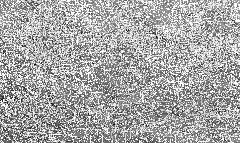
An STL file image of a region of the lampshade computer model (courtesy of Zeegine Ltd.). Having a plethora of facets caused additional difficulty in slicing and generating deposition toolpaths, leading to redundant toolpaths and consequently a longer printing time. STL, Standard Triangle Language.
Discussion and Conclusions
In recent years, plastic AM has started to be used as a series production technique in a small scale, especially in the consumer goods market. This study investigated the DfAM design practice that is adopted in daily work of designers, by which a new DfAM framework was developed. It consists of seven elements that have a significant effect on the design process, including AM process capability and limitations, production costs, designer's intents and considerations, design guidelines and rules, and production considerations. It provides guidance to designers throughout the design process for designing end-use consumer products for plastic AM volume production. Two examples of successful products that were sold on the market were studied, demonstrating the major elements in the framework as well as the feasibility of using plastic AM for end-use product design and manufacture. In addition, the impact of introducing plastic AM into design and production was discussed in the interviews.
Plastic AM products are generally of irregular shapes, which are difficult or not cost effective for series production using traditional processes, for example, the products shown in Figures 3 and 6. This enables designers to conceive wider design ideas, allowing them to focus more on product functionality while realizing the appearance that is more appealing to customers, as presented in The Design Process sections. This has far-reaching impact on various aspects of the product development process that was formed based on the traditional manufacturing processes. In addition to the broadened design freedom, the design process is simplified as a result of minimized or eliminated intermediate production stages, for example, tooling and assembly. Another influence caused by plastic AM is a better control of product cost. In injection molding, for instance, it is difficult to obtain a precise estimation of production costs until the tooling design is finalized. Whereas in AM, the major factors (e.g., part volume, printing time, and material usage) that determine the costs can be calculated in CAD/computer-aided manufacturing or other design software. This keeps the designer informed of any cost changes that are caused by the design changes, providing an accurate cost estimation in the design process.
“One of the big influences I can now see is that AM allows more people to get involved in product design. For traditional processes, there are quite a lot of process and geometry constraints. For example, you can't [sic] have an undercut feature for CNC machining. You need to think about material fluidity in injection moulding so you should design wall thickness very carefully. This is almost difficult for somebody who does not have plenty design and manufacturing experience. However, AM sort of [sic] requires less skills in the design process. I mean, AM brings the technology threshold down so that, like I just said, more people can get involved in both design and manufacture, which is very exciting. As a result, we will potentially have a wider product variety. That's [sic] a significant impact.” (interviewee ID16)
However, the broadened design freedom does not necessarily indicate design constraints or rules to follow. The interviews revealed that plastic AM parts were not for safety critical applications, primarily due to diminished surface quality, accuracy, and inferior mechanical properties. When designing a thin wall, despite the fact that it can be made by AM, it might be inherently weak, which may easily lead to a failure soon after the part is in use. Another aspect that is usually neglected by novices is that most plastic AM parts need postprocessing, which is a time-consuming and costly process. Moreover, the durability of plastic AM products is typically lower than traditionally manufactured products in certain circumstances where they are exposed to a strong sunlight (e.g., SLA products) or a moist environment (e.g., SLS products). Low durability requires designers to thoroughly assess the design of functional features, making necessary modifications to enhance the durability in certain application environments, for example, avoiding excess heat accumulation for the bulb cover described in The Design Process section.
From the production perspective, the most prominent impact of plastic AM is that it significantly reduces production costs, providing a new economically viable option for low-volume series production in terms of production time, cost, and material consumption. Due to simplified or eliminated intermediate production stages, for example, no tooling is required, and lead time and cost are thus substantially reduced. Raw material utilization is also increased compared with subtractive processes. However, it should be noted that the raw material utilization of plastic AM might not be as efficient as it is publicly advertised. Designers should be aware that certain amount of material needs to be sacrificed to form the final product, which is all accounted in the production costs, for example, surrounding powder in SLS and support structures in FDM. Despite both SLS and FDM being categorized as plastic AM processes, they have unique advantages and disadvantages. Based on the two case studies, it was found that SLS showed the capability to build more complex structures than FDM, which also exhibited a better surface quality. Whereas the production and maintenance costs of FDM systems were lower than SLS. An issue reported in the FDM moon-shaped lampshade in Case Study II: Design of a Moon-Shaped Lampshade section was the high print failure rate especially in printing a large object. On the contrary, SLS allowed the designer to focus more on the product appearance and functionality without paying too much attention on print failure rate, as presented in Case Study I: Design of a Desk Night Lamp section.
However, features produced by SLS are inherently brittle, and hence, designers need to ensure that the feature thickness is sufficient and certain packaging issues need to be addressed to reduce the risk of damage during transport. At present, most of the AM products found in this study are series produced in low production volume. The interviewees were confident that, with continued advancements in material availability and printing speed, AM will play an important role for medium volume production. However, it is not clear that AM can be used for mass production in the near future. Having said that, the intention of developing AM technologies is not to replace all existing production processes. Using AM for mass production might also largely weaken AM's unique advantages and magnify the process shortcomings, as presented in the Advantages and Disadvantages of Designing the Lampshade for FDM section. Moreover, high printer failure rate, high maintenance cost, and low-quality consistency of printed parts are other intractable issues to overcome for plastic AM to be a robust and economically viable series production technique. The abovementioned factors have made “design for AM for low- to medium-volume production” different to “design for AM for one-off customized product.” In the “design for AM for one-off customized product” scenario, product appearance and functionality that are tailored to the individual are usually considered to be more important than other factors, and the cost involved in printing such a customized product becomes less of an issue. Whereas in the “design for AM for low- to medium-volume production” scenario, in addition to the manufacturability of the products, production cost and quality consistency are the two most important factors to consider, as emphasized by more than 90% of the interviewees. These include printing speed, material cost and utilization (possibility to fit multiple products in one build), printer failure rate, and maintenance cost.
AM is apparently under rapid development toward a higher process reliability, wider material availability, faster printing speed, higher accuracy and surface quality, and so on. This requires designers to keep up-to-date knowledge on AM technology development, which will enable them to design products that take the latest advantages of AM processes. It is anticipated that, with technology advancement, the current design rules and considerations relating to AM process limitations and production costs would change. For example, features that are not suitable for AM series production at present due to either manufacturability or high product costs might be possible to economically produce in medium volume. In terms of plastic AM's influence on the environment, although it is promising in terms of waste material reduction, which is obviously beneficial for the environment, the interviewees raised concerns on the shortened life cycle, resulting in negative impact on the environment. The life cycle of an AM product is shorter than the injection molded one due to the low durability. In addition, some products are made of nondegradable polymers such as acrylonitrile/butadiene/styrene for FDM. The environmental impact needs to be addressed together with the development of new environmentally friendly materials.32,33
“I'm [sic] not quite sure how scrap material is recycled and reproduced. I had a chat with other companies which do 3D printing services, I mean, printing parts for customers, they said they just simply throw parts away that do not meet desired quality without thinking about recycling. This will definitely have a big and negative impact on the environment. AM makes production much easier than before. We can see the trend that more people can now take part in design and manufacture of their own stuff with just a proper desktop printer. Product life cycle becomes shorter. Products are less possible to be reused. From material point of view, if we fail to develop sustainable materials, we will get more waste eventually.” (interviewee ID07)
It is noted that the developed framework summarizes the main factors, considerations, design rules, and principles involved in designing a consumer product for plastic AM series production. It is anticipated that these factors, considerations, and rules would be different if designing for safety-critical engineering components or designing products for metal AM processes. Therefore, future research will explore wider application areas to categorize design considerations for different applications. Further work will also focus on developing a feature set consisting of a number of groups of features categorized by build time, mechanical properties, accuracy, surface quality, and production costs. These features will take advantage of plastic AM processes and will be included in the DfAM framework to assist designers to generate effective designs for plastic AM series production.
Footnotes
Author Disclosure Statement
No competing financial interests exist.
Funding Information
No funding was received for this research.