
Abstract
Additively manufactured cellular structures represent a promising engineering design concept for making customized products where user-specific mechanical properties are required. One of the major challenges in the additive manufacturing (AM) process is removal of unwanted support structures from the lattice. The support structure consumes extra material, printing time, and energy for manufacturing. Postprinting, it needs extensive postprocessing work to remove it from the lattice structure chemically or mechanically. In the case of flexible materials such as thermoplastic polyurethane (TPU), removing the support structure from the lattice is very difficult with the material extrusion process. In this article, a new type of a shell-shaped lattice structure inspired by sea urchin (SU) morphology is designed. This lattice can be additively manufactured by material extrusion processes such as fused deposition modeling (FDM) without requiring any support structures. The mechanical properties of the proposed structure, such as stiffness and energy absorption during loading and unloading, have been evaluated as they are important for cushioning. The compressive results indicate that the stiffness property is almost twice as high compared with the benchmarked, bending-dominated, body-centered cubic (BCC) lattice structure of the same relative density and ethylene vinyl acetate (EVA) foam. Energy absorption is almost equal to the BCC lattice and 20% better than EVA foam. Last, a predictive model on stiffness behavior and energy return was developed to facilitate a systematic way to select optimal densities of the SU lattice structure for energy-absorbing applications. Visual inspection has also revealed that there is no sagging or failure of the lattice, which reduced the manufacturing time and postprocessing time, saving a significant amount of material without compromising on quality. Supportless lattice printing was also validated by printing the specimen with a different FDM printer and TPU filament. A possible application for supportless lattice structures can be for AM of customized shoe midsoles at low cost, ski boots, tires, automotive crush boxes, or any other energy-absorbing structures.
Introduction
ASTM F42 has categorized the AM process into seven different types (as seen in Table 2) for a wide spectrum of applications with a variety of materials such as polymers, metals, and ceramics. For polymer printing, commonly used processes are fused deposition modeling (FDM),7–9 VAT photopolymerization, 10 powder bed fusion, 11 sheet lamination, 12 and material jetting. 13 Polylactic acid, acrylonitrile–butadiene–styrene, and thermoplastic polyurethane (TPU) are some of the polymers used by the FDM process for printing of parts.
In this study, the FDM process was chosen because it has a low operation cost with low maintenance, which also makes it the most popular AM process at present. 8 In FDM, the supporting material can be extruded from the secondary nozzle if support is built by a secondary material. For printing support with a similar material, extruders can be the same. Postprinting, the support structures are removed either by a mechanical process or chemical process. 4 The major manufacturers of the material extrusion-based system are Stratasys, Inc., for polymers; Desktop Metal, Inc., for metal printing; and MarkForged, Inc., for composite materials.
Man-made load-bearing structures are dense solids such as steel, concrete, and glass, but nature uses the cellular structure as a fundamental design tool for support such as in cedarwood, cork, and trabecular bone. The cellular structure is very porous and has a low-volume fraction of solids, which makes natural materials very efficient and optimal in terms of material.14,15
The unit lattice structure is made up of an interconnected network of solid struts or surfaces forming the basic building blocks (as seen in Fig. 4b), which can be tessellated in X, Y, and Z directions in a periodic or aperiodic manner.16,17 Physical, mechanical, and thermal properties of cellular materials such as density, thermal conductivity, and Young's modulus are important for the design of lattice structures and the most important structural characteristics are relative density (ρ*) and Young's modulus (E*). 14
where ρlattice is the density of the lattice structure and ρsolid is the density of the solid material. The value of relative density ρ* ranges from 0 to 1, where 1 indicates that the lattice is fully solid.
where E* is defined as
where Elattice and Esolid are Young's moduli of the lattice structure and solid material, respectively, and as defined by Gibson and Ashby, 14 the value of C1 in Equation (2) ranges from 0.1 to 4.0 and n depends upon the loading condition such as bending and stretching.
During fabrication of lattice structures with FDM, a support structure is provided throughout the printing process so that each lattice element is printed defect free and accurate without any distortion or sagging. This distortion can be warping due to residual stress, which is caused by sudden cooling of the extruded material from the nozzle and sagging or complete failure of the part due to the unsupported region. Hence, support structures are needed to provide a stable platform on which the lattice element is printed.
This support material is removed during postprocessing either by mechanical or chemical methods. 18 For hyperelastic or elastic materials such as TPU, there is no sacrificial material that could be used as support and hence the same material is used as support. Removing this support structure either chemically or mechanically from lattices is nearly impossible due to the intricate nature of lattices, and when compared with rigid thermoplastic, TPU has much lower viscosity and this leads to high intermolecular diffusion or healing between the two layers during the FDM process.19,20
Using support structures during fabrication of lattice structures consumes extra material, energy, processing time for printing, and extensive postprocessing work to remove the support. 18 There have been several works regarding how to design lattice structures for AM,21–27 but none of them focused on designing supportless lattice structures for the FDM process with TPU material.
The objective of this research is to design and print a self-supporting, stable lattice structure that will eliminate the need for support structures. These lattices should be embedded into the design space and printed without retraction and support with a TPU filament to make the FDM process more efficient with high speed and better build quality. In the present study, the lattice structure chosen is a shell-shaped lattice structure designed like a sea urchin (SU) as it has a mechanically stable and load-bearing shape. 28 This lattice can be additively manufactured without any support and almost no retraction of filament, which is important for printing flexible filaments.
The design of the lattice structure is influenced by three major properties of lattice structures: (1) properties of the material, (2) topology/shape and size of the unit lattice cell, and (3) the relative density/volume reduction coefficient (VRC) of the lattice structure.29,30
The results showed that supportless lattice structures significantly outperformed benchmarked, body-centered cubic (BCC) lattices and ethylene vinyl acetate (EVA) foams in terms of stiffness and energy absorption. A supportless lattice structure was also fabricated with varying density for establishing a predictive model on stiffness behavior and energy return percentage of these structures. This will facilitate a systematic way to select the optimal densities of SU lattice structures for energy-absorbing applications. Supportless and continuous lattice printing claims were also validated by fabricating the specimen with a different FDM printer and TPU filament to compare the time and cost of making such structures with structures that contain the support.
Experimental Design
Materials
The cellular supportless lattice structure was fabricated using a TPU filament of 1.75 mm diameter produced by Daytay Plastic Industry Ltd. (Taiwan). TPU is a linear, segmented block copolymer containing alternating hard (adduct of di-isocyanate and small glycols) and soft (e.g., polyester and polyether) segments connected to each other by urethane groups (-NH-COO-). By varying the amounts of hard and soft segments, the properties can be varied over a wide range. To find the material property of the TPU filament, ASTM D638 type 431,32 standards were followed and samples were printed on the FDM machine (Flashforge Beaver 3) with the print direction being the same as the applied force with 100% infill, as seen in Figure 1a. Tensile dog-bone samples were modeled in Creo Parametric 3.0 and exported to the STL file for slicing using Simplify3D software to generate G-code files.

Dog-bone samples were printed with the same parameters as explained in the AM of supportless lattices section and three random samples were taken for tensile testing on the MTS universal testing machine (MTS Systems Corporation) with a 10 kN load cell and strain rate of 20 mm/min. The material property and stress–strain graph obtained can be seen in Figure 2.
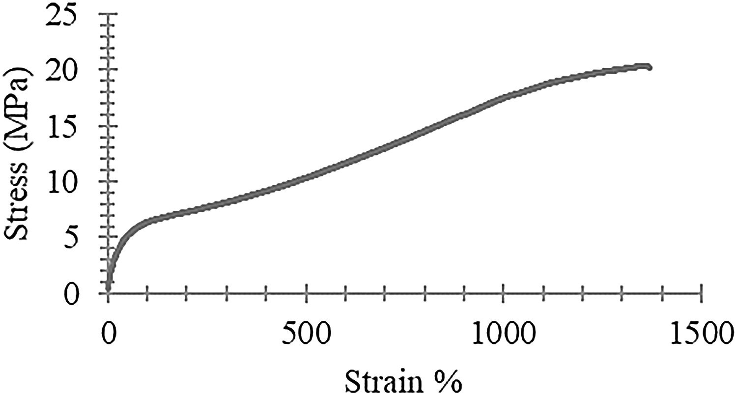
Typical stress–strain plot of printed TPU by FDM. TPU, thermoplastic polyurethane.
TPU material properties are listed in Table 1 and the same printing parameters were also followed for printing the supportless lattice structure. A rectangular sample of EVA foam from the research and development center of Far Eastern New Century Corporation (Taiwan) was also used for benchmarking. This material is normally used for cushioning applications.
Material Properties of the Thermoplastic Polyurethane Filament
Design of supportless lattice structures
In AM, each process has its own requirements for producing supportless structures and for some supports that exist by default and cannot be eliminated, as described in Table 2. In the FDM process, supports are used when lattice structures have steep overhangs and parallel ledges, as seen in Figure 3a.
Support Structure Requirements of the Additive Manufacturing Process
ADAM, atomic diffusion additive manufacturing; AM, additive manufacturing; BJ, binder jetting; CDLP, continuous digital light processing; DLP, digital light processing; DMLS, direct metal laser sintering; DOD, drop on demand; EBAM, electron beam additive manufacturing; EBM, Ebeam; FDM, fused deposition modeling; LENS, laser-engineered net shape; LOM, laminated object manufacturing; MJ, material jetting; MJF, multijet fusion; NPJ, nanoparticle jetting; PVA, polyvinyl alcohol; SLA, stereolithography; SLM, selective laser melting; SLS, selective laser sintering.
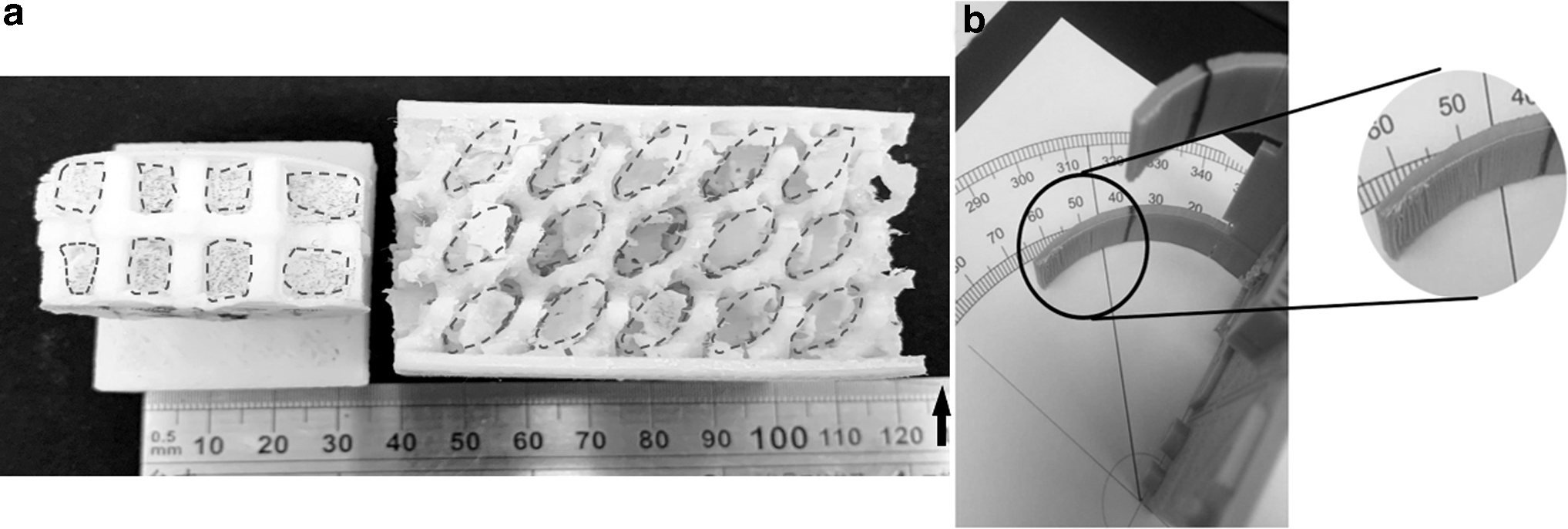
Thomas 33 and Cloots et al., 34 with the experimental method, concluded that the lowest orientation to be printed without curl is 45° with a 0.5-mm parallel ledge for the selective laser melting process. The experimental method was designed to identify the same for the FDM process. As seen in Figure 3b, with visual inspection, distortion in the part was seen after 45°. With this result, it can be inferred that to design a supportless lattice structure for the FDM process, two important considerations are (1) the maximum overhang angle should be 45° and (2) the parallel ledge should be eliminated.
Bhate et al., 17 explained that incorporating the lattice structure into the design space has to follow four steps: (1) design of the unit lattice (beam type or shell type) based on application, (2) selection of unit size of the lattice, (3) selection of parameters for optimization, and (4) connectivity of the lattice in the design space. According to Tancogne-Dejean et al., 35 stiffness of the plate or surface-based lattice structure is higher than the truss-based lattice. Contemplating these requirements, the unit lattice structure designed in this work is a surface-based cubic lattice.
The shape of the unit lattice is designed like a regular SU structure of the Echinoidea class (Fig. 4a) with a focus on structural morphology, as seen in Figure 4b. AM technology with layer manufacturing has made it possible to fabricate complex parts such as the natural geometry of SU shells with ease. This plate structure is characterized by its remarkable ability to transfer any kind of stress evenly on its surface. In the work by Malcolm 28 and many other researchers,36–39 they have explained that the design of the urchin or dome-type structure is economical in materials as compressive stress is transferred very effectively from the surface of the dome to the margin of the dome or ambitus of the urchin. This makes this kind of surface more stable and stronger and, as a result, it has been used for architectural design,36–39 but it has hardly been explored for lattice design in AM technology.
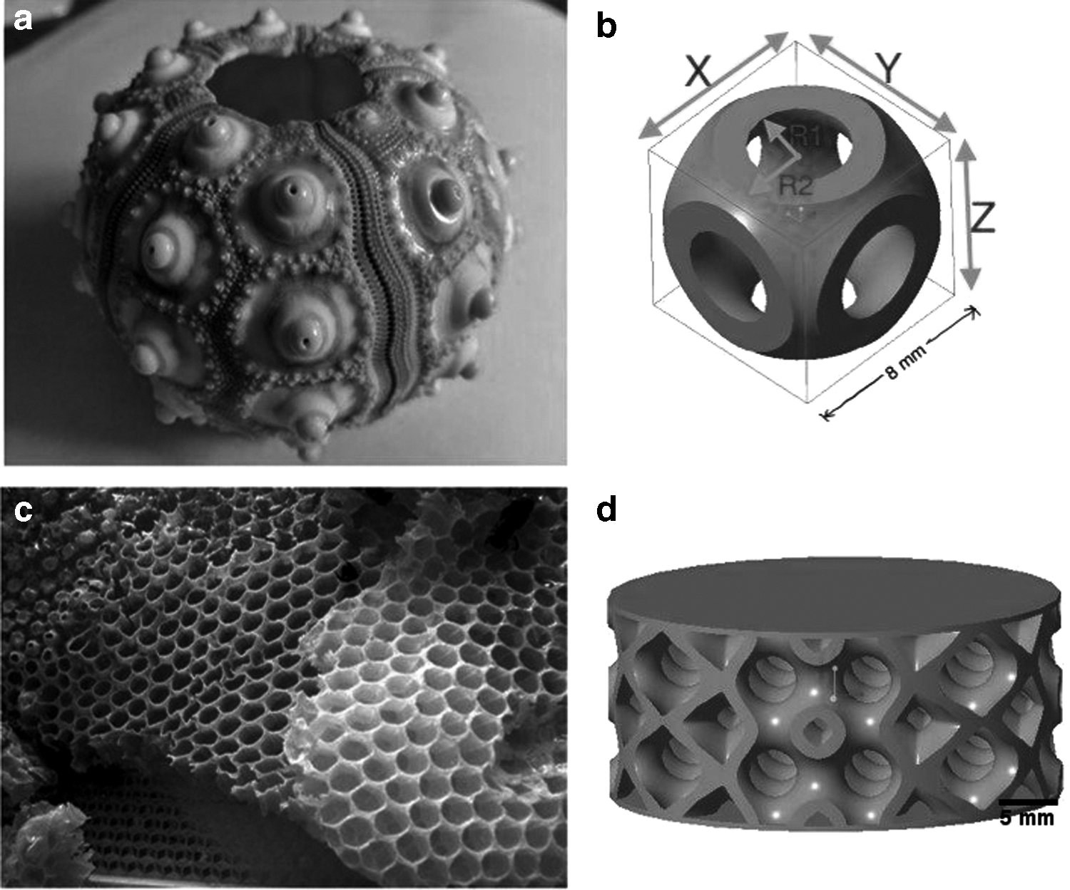
Philippi and Nachtigall 40 have analyzed the mechanical response of a regular SU shell under various external loading conditions through finite element analysis, and results were analyzed to understand the shell shape and mechanical behavior. Tessellation depends on the close packing concept as explained by Pearce, 41 so the unit lattice, which has six faces, is surrounded by exactly six lattices in X, Y, and Z directions and is tightly packed, as densely as possible. This type of packing or connection has left no void between lattices, as seen in Figure 4d, and this can also be seen in nature in a bee honeycomb (Fig. 4c) or collagenous fiber plate. This kind of tessellation with face-to-face connection in all three directions covering the design space, makes the lattice structure periodic and unary type.
The design is reproduced in Creo Parametric© in the form of a nonuniform, rational B-spline surface on the faces of a primitive cubic lattice. The inner radius R1 and outer radius R2 are two important design parameters, as seen in Figure 4b, as the VRC ϕ is controlled by both radii, and X, Y, and Z control the size of the unit lattice structure.
where VL is the volume of the lattice and Vs is the volume of the solid lattice.
The size of the unit lattice selected for this study is constant after understanding the FDM process capabilities 42 at 8 × 8 × 8 mm with density/VRC being variable. Tesselation of the lattice structure in the design space is done on the cylinder of diameter 38 mm and thickness 16 mm with 0.5 mm skin on both sides, as seen in Figure 4d, with trimming of lattice within the design space as no dangling of beam is seen at the outer area. For comparison of energy absorption and stiffness, the BCC lattice structure was also designed as this structure can also be printed supportless and is very effective in energy absorption.43,44
AM of supportless lattices
The fabrication process was carried out using the FDM machine Flashforge Beaver 3 from Mastech Machine Co. Ltd., (Taiwan) after performing the capability study of FDM42,45 with a TPU filament 1.75 mm in diameter. No special extruder was selected for printing this flexible material, buckling of the filament is avoided due to no retraction and continuous print of the cellular lattice structure. The STL file was sliced using the Simplify3D LLC, version 3.0, software with printing parameters optimized for printing the TPU filament listed in Table 3.
Fused Deposition Modeling Parameters Used for Printing All Lattice Structure and Dog-Bone Samples with the Thermoplastic Polyurethane Filament
These data were uploaded to the FDM machine for AM and validation of the design. The printing orientation of all parts was the same as in Figure 5a, with environment temperature maintained at 20°C–24°C. No postprocessing is done after manufacturing and various designs of the supportless lattice structure were printed with the same parameter as seen in Figure 5. Design details can be seen in Table 4.

Fabrication using the FDM process of
Specification of Supportless Lattice Used in the Study
VRC, volume reduction coefficient.
Results and Discussion
Three specimens of each different lattice structure designed were fabricated with a material extrusion process, as seen in Table 4 and Figure 5b. Three specimens of the bending-dominated, truss-based, BCC lattice structure were also fabricated with the same process and parameters.
Visual inspection
Visual inspection under the 4 × magnification lens found no imperfection or broken lattice within the structure, which confirms the ability to fabricate the supportless lattice for end-user products. This novel and complex supportless lattice structure, which is impossible to manufacture with traditional manufacturing methods, proves that it can reduce the manufacturing time and postprocessing time, saving a significant amount of material without compromising on quality. Furthermore, these lattices are well suited for fabrication based on the extrusion process with a broad range of unit lattice sizes based on application.
Energy absorption of the lattice structure
The stiffness and hysteresis of the supportless lattice were quantified using the MTS universal testing machine (MTS System Corporation) with a 10 kN load cell. To calculate energy loss during loading and unloading as well as the stiffness of the structure, each lattice structure was placed between two flat metal fixtures and cyclic tests were performed as seen in Figure 6. Each lattice structure was subjected to 20 consecutive loading and unloading cycles to ensure that it reaches steady-state hysteresis46,47 and data of the 21st cycle were used for analysis.
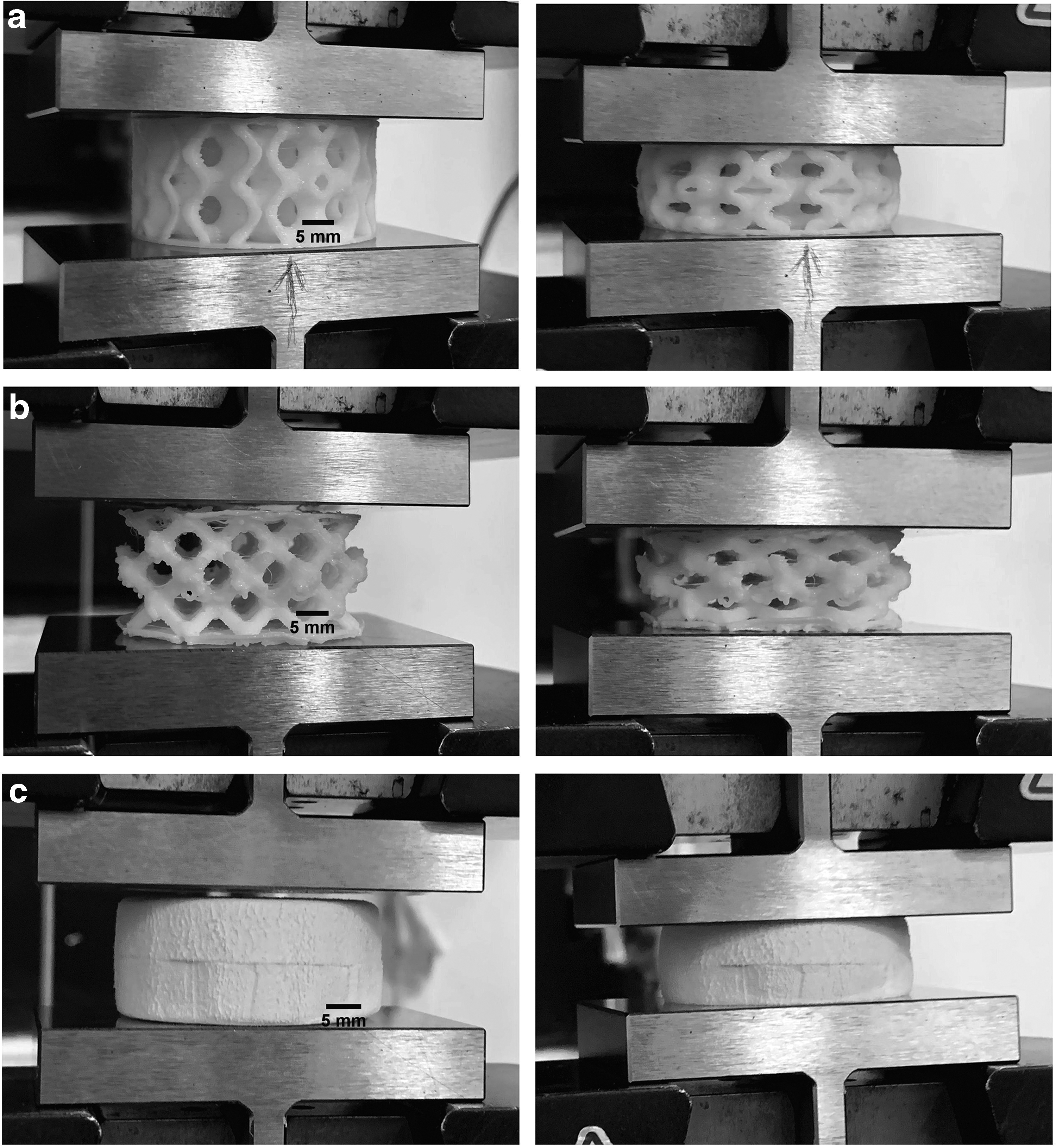
Loading and unloading test performed on
This was also proved during pilot testing of the lattice and it was observed that after the 15th cycle, a steady state was reached. During each cycle, lattice structures were compressed at a strain rate of 5 mm/min with displacement up to 35% of height. After each cycle of loading and unloading, a 10-s pause was applied because the viscoelasticity of the material causes the structure to take time getting back to the starting position.
A rectangular sample of EVA foam was also used for comparison of energy absorption in lattice structures. The sample was cut into a circular shape of the same dimension as the other lattice structure fabricated. EVA foam samples along with supportless lattice and BCC truss-based lattice with comparable VRCs were used for comparing stiffness and energy absorption.
The force–deformation curve of the loading and unloading test on the supportless lattice with constant unit lattice size, but with various relative densities, can be seen in Figure 7. The stiffness of each lattice structure was determined by calculating the slope of a line best fit to the loading curve. The area under the loading curve of the lattice structure is the energy absorbed by the lattice and the area under the unloading curve is the energy return of the lattice and this was calculated to find energy loss. Hence, the energy lost is the hysteresis, which is the area between the loading and unloading curves. 48
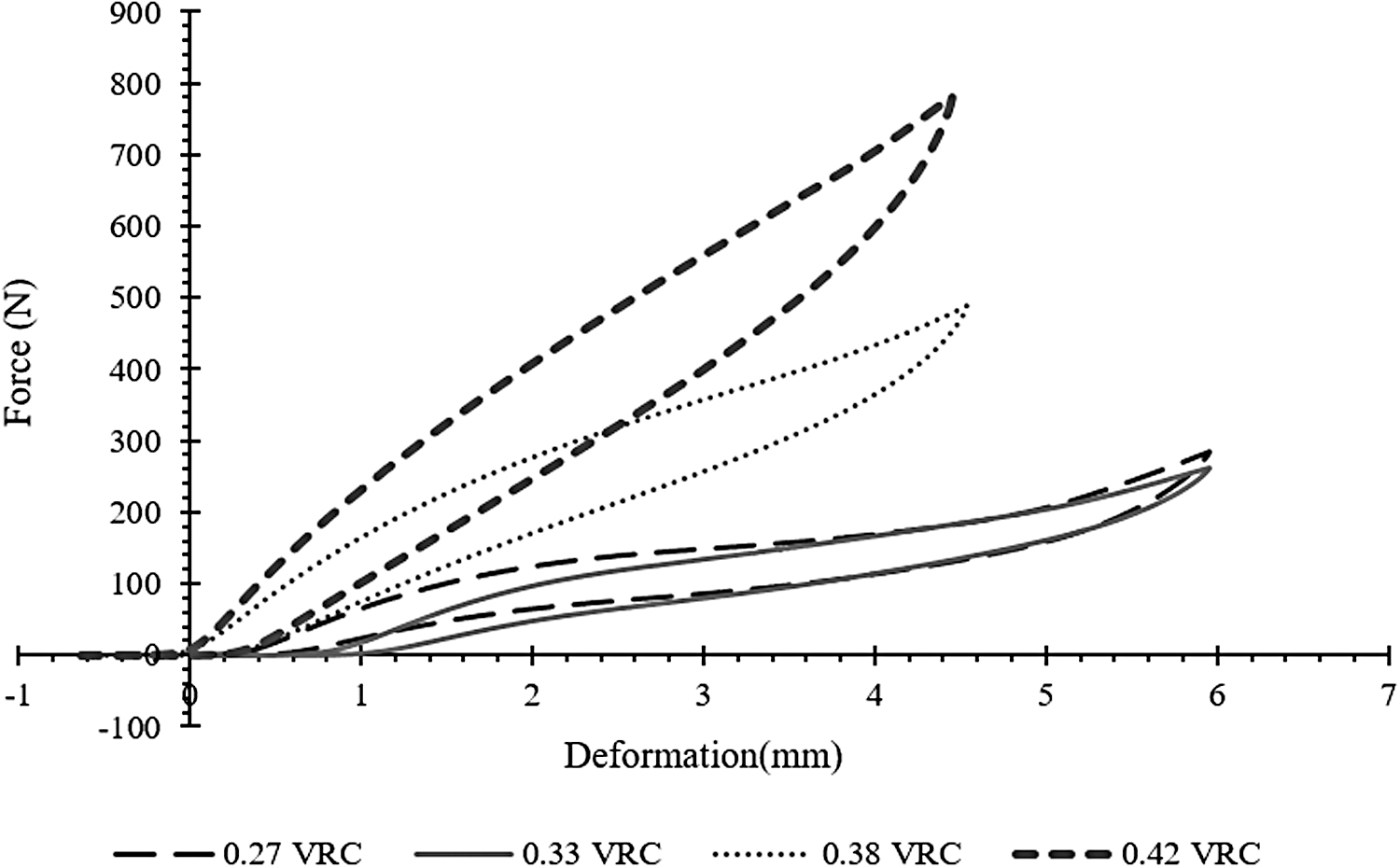
Force–deformation curves obtained from loading–unloading cycles for each lattice of different density/VRC. VRC, volume reduction coefficient.
The same procedure was done for each lattice structure to understand the effect of VRC or relative density when the unit lattice size is constant. It can be seen in Table 5 that as the relative density increases, the stiffness of the lattice structure increases, but energy loss is constant for all structures. As reported by Worobets et al., 46 for cushioning applications, the increase in stiffness leads to a decrease in energy loss. However, this novel lattice structure has consistent energy loss across all relative densities and has a multifold increase in the load-bearing capacity.
Energy Loss Percentage Value of Each Lattice with Different Volume Reduction Coefficients
BCC, body-centered cubic; EVA, ethylene vinyl acetate; SU, sea urchin.
Supportless lattices were further investigated with the bending-dominated BCC lattice 49 with VRC of 0.33 and EVA foam, which is the popularly used material for cushioning applications, as seen in the loading–unloading curve in Figure 8. The bending-dominated BCC lattice is known for high energy absorption and this ability can also be seen in Table 5 as it shows the lowest energy loss among all lattices.
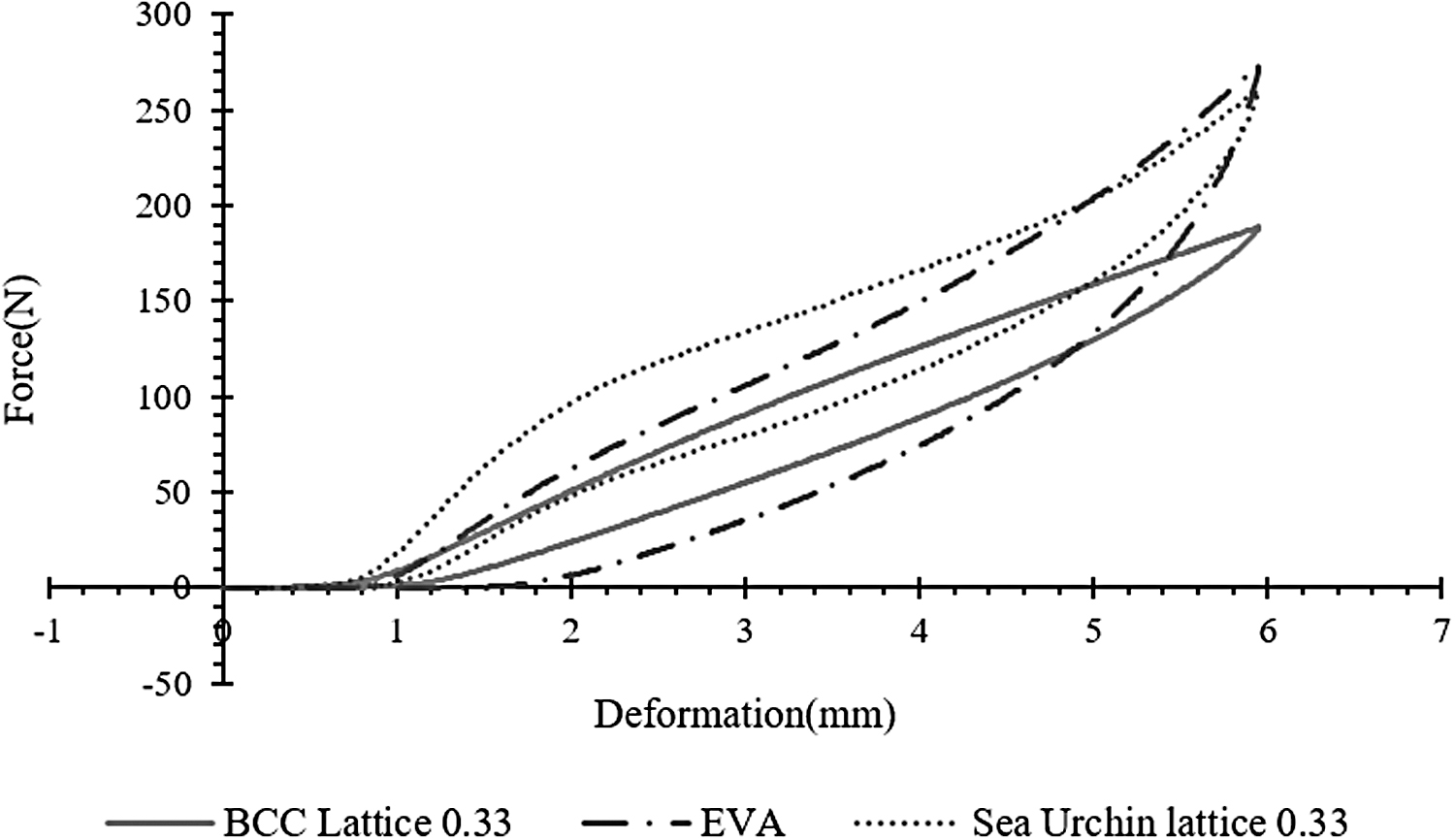
Force deformation curves obtained from loading–unloading cycles for the BCC lattice, SU-inspired lattice, and EVA foam.
The SU supportless lattice structure has almost the same energy loss compared with the BCC lattice, but the stiffness is more than two times better compared with the BCC structure. EVA foam energy loss is almost 1.5 times higher compared with the SU lattice and BCC lattice, whereas the stiffness of the SU lattice structure is 1.4 times better than EVA foam. Overall, the SU supportless lattice structure shows better stiffness and almost equal energy-absorbing capabilities compared with the BCC lattice structure.
Effect of relative density on lattices
The effect of VRC/relative density on supportless lattice structures when the unit lattice size is constant was also investigated in this study. Lattice structures were fabricated with three specimens, each with a different thickness (T = R2 − R1) on FDM, as detailed in Table 6. Each specimen's stiffness was quantified using the same method as the earlier samples and data of the 21st cycle were taken for calculation of stiffness. The average stiffness values of three specimens with different thicknesses (T) were calculated, as seen in Table 6.
Average Stiffness of the Lattice Structure with Various Densities
To establish the predictive model for the material behavior of the SU-inspired supportless lattice with respect to unit lattice thickness (T), the SU lattice structure was fabricated using a low-cost FDM printer with a nozzle diameter of 0.4 mm. The experimental result shows that unit lattice thickness from 0.4 to 0.8 mm has a very uncertain stiffness because during fabrication of these structures with a 0.4-mm nozzle diameter, the infill could not be generated properly.
When the thickness of the lattice structure passes beyond 0.8 mm, the stiffness rises steeply up to 520 N/mm for unit cell thickness (T) 1.5 mm, as seen in Figure 9. Stiffness is due to resistance against buckling of the walls of the cellular lattice. The rise of the stiffness value can be understood from the fact that beyond 0.8 mm thickness, the printing extruder can make full infills, which was not possible from 0.4 to 0.8 mm wall thickness. The data points of stiffness values for all samples were plotted and two linear best curve fit models were established.
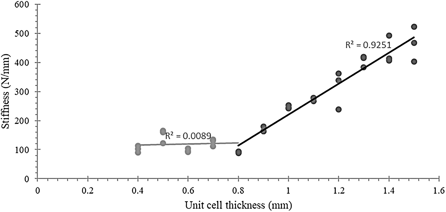
Predictive model for the material behavior between stiffness and thickness of the supportless lattice.
Equation (5) is the linear best curve fit model when the supportless lattice thickness (T) ranges from 0.4 to 0.8 mm and Equation (6) when the thickness (T) ranges from 0.8 to 1.5 mm. Beyond 1.5 mm, the increased thickness of shells is expected to make the structure behave more like a dense solid rather than shell-based cellular structures responsible for energy return properties. Gibson and Ashby 14 lattice structures with density larger than 30% are better represented as solid structures with holes.
The curve fitting in Figure 10 shows that the total energy return percentage is almost constant for all samples, irrespective of VRC/relative density. This supportless lattice structure shows a near-constant energy loss of around 30%, that is, total energy absorption of 70% with varying stiffness. The average range of energy absorption for all the samples is between 65% and 70%. All the test results obtained were under quasi-static cyclic loadings and no failure occurred in the specimens. Hence, the supportless lattice structure is able to recover after the loading–unloading cycle, which indicates repeated energy absorption of this lattice structure.
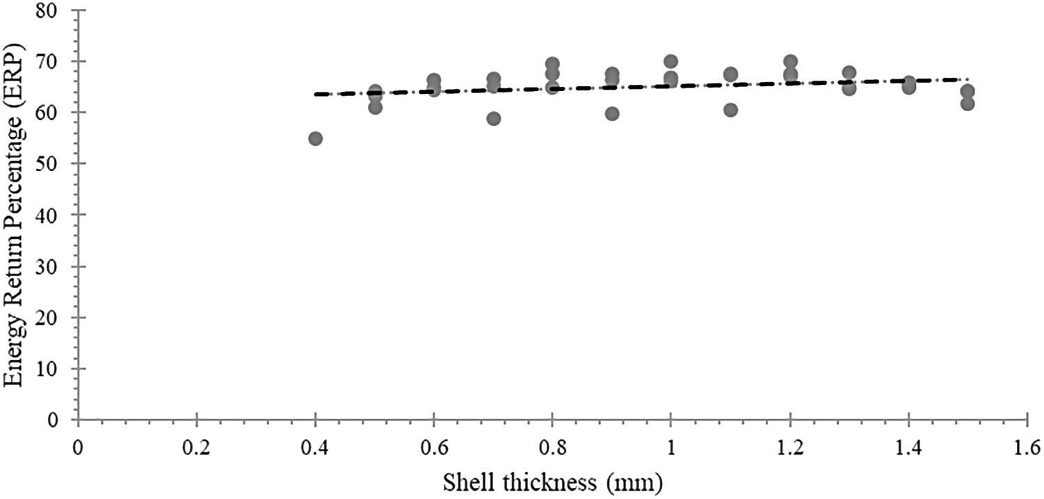
Energy return percentage versus supportless lattice structure thickness.
Validation
Validation of the supportless fabrication with a different make of FDM printer and TPU filament was done using the Ultimaker-3 3D printer with a TPU filament having the same hardness of 95 Shore A from the same manufacturer. The printing speed was kept at 1500 mm/min with a 0.2-mm layer height for all three samples. Three specimens as seen in Figure 11 were fabricated with (1) the SU lattice structure without support and with continuous type fabrication, that is, no retraction is allowed in the process; (2) SU lattice structure with polyvinyl alcohol (PVA) filament as a support material with continuous type fabrication; and (3) BCC lattice structure without support and with retraction.

Printing of specimens with the Ultimaker FDM printer and Ultimaker TPU filament.
All three samples had a VRC of 0.33. Printing time was noted down for all three samples, including the postprocessing time in cases where samples were printed with PVA support. Printing cost was calculated only for the material and other overhead costs were not used for this calculation.
After fabrication of all three specimens as seen in Figure 11(e2, e3, e4), printed specimens were compared with specimens benchmarked, Figure 11(e1), which was a printed sample of Figure 5. Stringing was seen in the printed sample with Ultimaker FDM, but no defect was observed in the specimens and stringing could be avoided with further advance retraction process optimization.
The printing time, as seen in Figure 12, is less for SU lattice structures with no support when compared with the other two samples; SU lattice with support was printed with an extra 3 h compared with SU lattice with no support and 11 h for removing the PVA support chemically. The BCC lattice structure took 9 min extra compared with the supportless SU lattice.

Printing time of specimens printed with Ultimaker FDM.
The cost for fabrication of these specimens was calculated with material consumption. The TPU filament costs 82 USD/750 g and PVA costs 62 USD/350 g. The total weight of printed specimen structures, SU with no support and BCC with no support, was 10 g, whereas SU with support had 10 g of TPU and 12 g of PVA support. As seen in Figure 13, the SU lattice with support had three times higher cost when compared with no support. This cost can further add up when calculated with overhead costs such as labor cost, electric cost, maintenance cost, and manufacturing cost.

Printing time of specimens printed with Ultimaker FDM.
Conclusion
This study evaluates the AM of supportless lattice structures with TPU filaments and material extrusion processes such as FDM for the application of energy absorption. This has a manufacturing advantage as the support fabricated by the flexible material (TPU) for the lattice structure is very difficult to remove either chemically or mechanically. Supportless lattice structures inspired by SU shells can improve the overall speed of the AM process for building customized parts. This periodic supportless lattice offers great potential for fabrication parts with a wide range of volume fraction/density values and different unit cell sizes. This type of lattice reduces the material, energy consumption, and production time since postprocessing to remove the support structure can be eliminated.
Visual inspection under the 4 × magnification lens found no imperfection or broken lattice within the structure, which confirms the ability to fabricate the supportless lattice for end-user products. This novel and complex supportless lattice structure, which is impossible to manufacture with traditional manufacturing methods, proves that it can reduce the manufacturing time and postprocessing time, saving a significant amount of material without compromising on quality.
The energy return capacity of the supportless lattice structure under cyclic loading for various densities of the lattice is almost constant and an increase or decrease in stiffness value does not have much influence on energy loss or energy return.
The supportless lattice structure has almost identical energy loss compared with the bending-dominated BCC lattice, but stiffness is two times better compared with the BCC structure. EVA foam energy loss is almost 1.5 times higher compared with the SU Lattice and BCC lattice, whereas stiffness of the SU lattice structure is 1.4 times better than EVA foam. Overall, supportless lattice structures exhibit superior mechanical properties.
The experimental results also show that unit lattice thickness (T) from 0.4 to 0.8 mm has an almost constant value of stiffness, which ranges from 90 to 150 N/mm. When the thickness of lattice (T) is beyond 0.8 mm, stiffness rises steeply up to 520 N/mm for thickness (T) of 1.5 mm.
The fabrication time of the supportless lattice was 3 h less when compared with specimens printed with support and 11-h reduction of postprocessing hours. The same also took 9 min of lesser fabrication time when compared with the BCC structure of the same volume fraction, but with a noncontinuous type printing requirement. The cost for printing this was three times less compared with specimen printed with support.
Hence, a supportless lattice structure can strengthen the capability of the AM process for fabricating load-bearing parts with less weight, high speed, and less cost.
Future Work
The expected application of this supportless lattice structure is in development of customized midsoles of sports shoes and ski boots by the material extrusion process. The effect of flow rate on the accuracy of printing using a fixed nozzle diameter will also be investigated.
Footnotes
Acknowledgment
The author would also like to thank Kenneth C. Huang for proof reading.
Author Disclosure Statement
No competing financial interests exist. The design patent of a supportless lattice structure has been filed at the US Patent and Trademark Office (18PV0123US) and Taiwan Patent.
Funding Information
This work was financially supported by the High Speed 3D Printing Research Center from the Featured Areas Research Center Program within the framework of the Higher Education Sprout Project by the Minister of Education (MOE) (Grant No. 108PO12) in Taiwan.