
Abstract
Lattice materials represent one of the utmost applications of additive manufacturing. The promising synergy between additive processes and topology optimization finds full development in achieving components that comprise bulky and hollow areas, as well as intermediate zones. Yet, the potential to design innovative shapes can be hindered by technological limits. The article tackles the manufacturability by laser-based powder bed fusion (L-PBF) of aluminum-based lattice materials by varying the beam diameter and thus the relative density. The printing accuracy is evaluated against the distinctive building phenomena in L-PBF of metals. The main finding consists in identification of a feasibility window that can be used for development of lightweight industrial components. A relative density of 20% compared with fully solid material (aluminum alloy A357.0) is found as the lowest boundary for a 3-mm cell dimension for a body-centered cubic structure with struts along the cube edges (BCCXYZ) and built with the vertical edges parallel to the growth direction to account for the worst-case scenario. Lighter structures of this kind, even if theoretically compliant with technical specifications of the machine, result in unstable frameworks.
Introduction
A lattice is an architecture that derives from the regular repetition of a structural unit, the so-called unit cell, in all directions. Lattices, as well as (solid) foams and sponges, belong to the wider category of cellular solids. However, the structural periodicity distinguishes lattices from foams (having open cells) and sponges (having closed cells), whose architecture is instead stochastic.1,2 Lattice materials lie at the boundary between composite materials and monolithic materials because at the microscale, they consist of two separate phases, namely solid struts and void parts, and hence they can be described as composites, but at the macroscale, they show a consistent set of effective properties and therefore can be treated as monolithic materials. 1
The periodic architecture can be designed to provide the lattice material with specific functions. One of the most important benefits of lattice materials is lightweighting for structural applications, which is based on optimization of the stiffness- (or strength-) to-weight ratio. 3 Using as little material as possible is particularly important in automotive and aerospace industries, where any mass saving, also minimal, brings about a sensible reduction in cost and often an increase in performance.4–6 For this reason, attempts have been made to scale the lattice optimization approach to the design of macroscale structures such as the piston of an internal combustion engine 7 or even the automotive chassis. 8 However, lattice materials have many other applications, such as heat exchangers, energy absorbers, biomedical devices, and thermal and acoustic insulators.1,9
So far, several conventional methods have been proposed to manufacture metal-based lattice materials, including investment casting and metal wire approaches.1,10 However, these techniques often use very complicated equipment and require subsequent assembly or bonding procedures to achieve the desired lattice structure. According to a recent survey of the available literature, there exists no traditional manufacturing method that enables the production of lattice structures without subsequent assembly or postprocessing treatments. 11 This implies that the feasible architectures are very limited when working with conventional processes. 1
A revolutionary approach to production of metal lattice materials relies upon additive manufacturing (AM) techniques. AM is addressed to the construction of three-dimensional objects by the progressive addition of material, usually in a layer-wise manner. In principle, this allows for an unprecedented freedom in geometry, which includes production of multipart assemblies, enclosed and interlocking parts, workpieces with conformal cavities, and complicated lattice structures. 12 Since the fabrication costs are governed by the cost of the feedstock material (i.e., the weight of the part and of the supporting structure) and even more markedly by the build time (i.e., the volume or height of the part), this geometric complexity comes for free and lattice structures are often cheaper to be built by AM than fully solid parts.13,14 AM techniques significantly reduce the time and cost to market compared with conventional manufacturing methods. Moreover, sudden changes in design models can be readily implemented without additional expenses. For these reasons, AM is well suited to the production of prototypes, customized single parts, or small volume productions. 15
For metals, the most important AM techniques can be grouped into two families, namely powder bed fusion (PBF) methods, which include laser-based PBF (L-PBF) and electron beam melting (EBM), and direct energy deposition (DED) methods, which include wire and powder laser metal deposition. Among them, DED is rarely used to produce lattice materials, whereas PBF techniques are prevailing for this application. 11 L-PBF is based on a laser beam to selectively melt a powder bed layer upon layer. Since the laser beam affects a very small volume of material compared with the entire volume of the part and since the surrounding powder bed is just moderately heated, extremely high cooling rates are locally established, thus engendering very fine microstructures, out-of-equilibrium phases, and reduced segregation with respect to conventional cast counterparts.16,17
L-PBF works with relatively fine powders (mean diameter: 30 μm) compared with EBM (mean diameter: 70 μm) and the size of the laser spot is much smaller than that of the electron beam (in EBM, a large spot is needed to limit local charging and consequent repulsive forces between particles). L-PBF is therefore a nearly net shape technique since the surface finish is relatively good, with Ra values typically in the 4–11 μm range against the 25–35 μm range commonly encountered in EBM. Moreover L-PBF allows for a better geometric tolerance (±0.05 to ±0.10 mm for L-PBF and ±0.20 for EBM) and a lower minimum feature size (as low as 40 μm for L-PBF and 100 μm for EBM).18–21
In principle, L-PBF paves the way for production of any lattice structure that derives from topological optimization for a given application. Nonetheless, some issues are still under debate. For example, the size of the unit cell depends on the thickness (or diameter) and length of its struts and on the geometry of connecting nodes. In the main, larger cells are not only easier to print, at least if they do not include overhangs, but can also show a more stepwise response. Vice versa, smaller cells give place to more homogeneous system responses, but their printability is limited by the minimum feature size. In addition, the material choice is not neutral. The geometry being the same, choosing a stiffer metal will result in a stiffer lattice material. On the other hand, lattice materials printed from a stiffer metal generally enable a greater design freedom, with thinner struts and larger cell sizes. Another parameter to be considered is the relative orientation of the unit cell with respect to growth direction because it affects the number and placement of overhanging areas that would require supports, which instead should not be used as they would be impossible to remove. In theory, a well-sized and oriented unit cell for a given build material should fulfill self-supporting restrictions.
The present contribution aims at clarifying the feasibility of lattice materials by L-PBF of A357.0, which is a relatively new entry in the market of industrial feedstocks. Aluminum alloys are well suited to produce lattice materials due to their excellent specific strength. Moreover, aluminum-based cellular structures are expected to experience large plastic deformation and hence to absorb important impact energy under quasi-static and dynamic loading. 9 Nonetheless, a limited number of contributions have been dedicated so far to production of AlSi10Mg-based lattice materials by AM,3,22–25 and to the best of the authors' knowledge, this is the first time that the printability of A357.0 into lattice materials is openly and thoroughly discussed. The lattice geometry was created by repetition of a BCCXYZ unit cell, which is shown in Figure 1. The BCCXYZ unit cell corresponds to a body-centered cubic cell with additional struts on all edges of the cube, thus preserving the geometric condition of cubic symmetry. Nonetheless, it is known that AM parts are anisotropic along the growth direction26,27 and therefore the structure and size of the obtained lattice materials were accurately investigated, also taking into consideration the potential development of process-induced anisotropy.
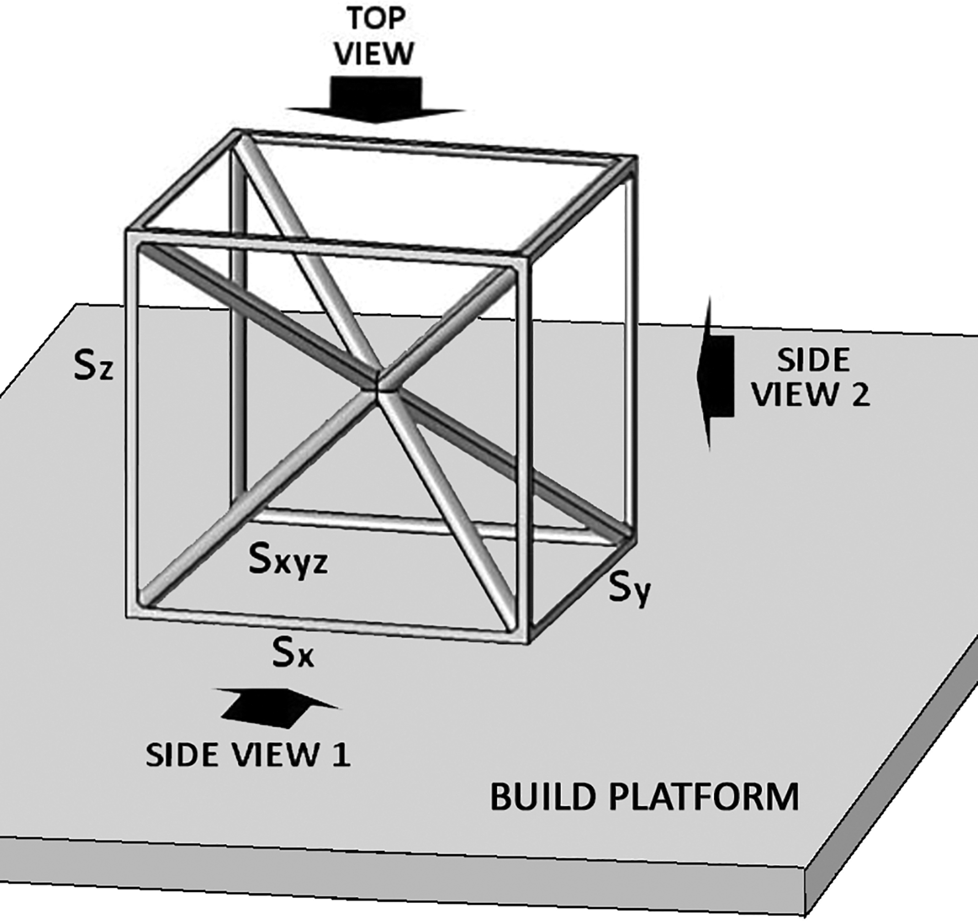
BCCXYZ unit cell.
Materials and Methods
The lattice materials were built on an SLM® 500 machine (SLM Solutions Group AG, Lübeck Germany) operated with a scan speed of 1100 mm/s, laser power of 350 W, and layer thickness of 0.050 mm. The applied process parameters were optimized for lattice structures based on consultancy with the machine developer. The geometry in Figure 1 was oriented in such a way that the struts labeled Sz were parallel to the growth (Z) direction. After printing, all the specimens were T6 treated under an inert atmosphere, which implied heating at 540°C for 16 h, water quenching down to 30°C/35°C, and artificial aging at 160°C for 10 h. The chemical composition of the feedstock powder is detailed in Table 1. 28 The powder had a granulometric distribution with D(10) = 22 μm, D(50) = 45 μm, and D(90) = 83 μm.
Chemical Composition (wt%) of the Feedstock Powder 28
To check the feasibility of lattice materials on a relatively large dimensional scale, cubic samples were designed and printed having an edge length approaching 48 mm. To this aim, the size of the single BCCXYZ unit cell was kept constant at 3 mm and the lattice was generated by repeating the unit cell by 16 times along each edge. The struts were designed with a uniform round cross section, and to reduce the relative density (which is the density of the lattice material normalized by the full density of A357.0, i.e., 2.67 g/cm3) of the different groups of samples, the nominal diameter of the struts was progressively lowered from 0.70 mm for group 3.4 (relative density: 40%) to 0.30 mm for group 3.05 (relative density: 5%). The complete list of the sample groups, with corresponding dimensional parameters and nominal relative density values, is reported in Table 2. In more detail, the computer-aided design (CAD)-based models were drawn by CATIA V5 R21 software (Dassault Systèmes, Vélizy-Villacoublay, France) and saved as .STL files. Taking into account the cubic symmetry of the unit cell, only one-eighth of the cell was generated in the CAD software and then repeated considering any rotational and planar symmetry.
Details of .STL Files, Strut Diameters, and Densities of the Lattice Materials
The mass of the lattice sample was measured with an electronic balance (Ohaus, model PA 124C, Ohaus Europe GmbH, Switzerland). As to the volume, for the single sample, the average length of each side was calculated on three different points and volume was calculated as the volume of a rectangular prism. The experimental density was hence determined as the mass-to-volume ratio. The experimental relative density was expressed as the fraction of the experimental density of the lattice material to the full density of A357.0. For the 3.1 group, whose geometry was incomplete due to manufacturing issues, as a first estimate, the volume of each sample was approximated to the volume of the circumscribed prism. As a consequence of the approximated volume, the experimental density and relative density were underestimated and considered as mere guidelines.
The lattice materials were observed under a stereomicroscope (SMZ1270, Nikon, Japan) to measure the average diameter of the struts in different orientations. At least 10 struts were considered on each view. For higher magnifications, which were required to understand the build quality, the samples were also observed under a scanning electron microscope (Quanta-200; FEI, The Netherlands).
Results
Printability
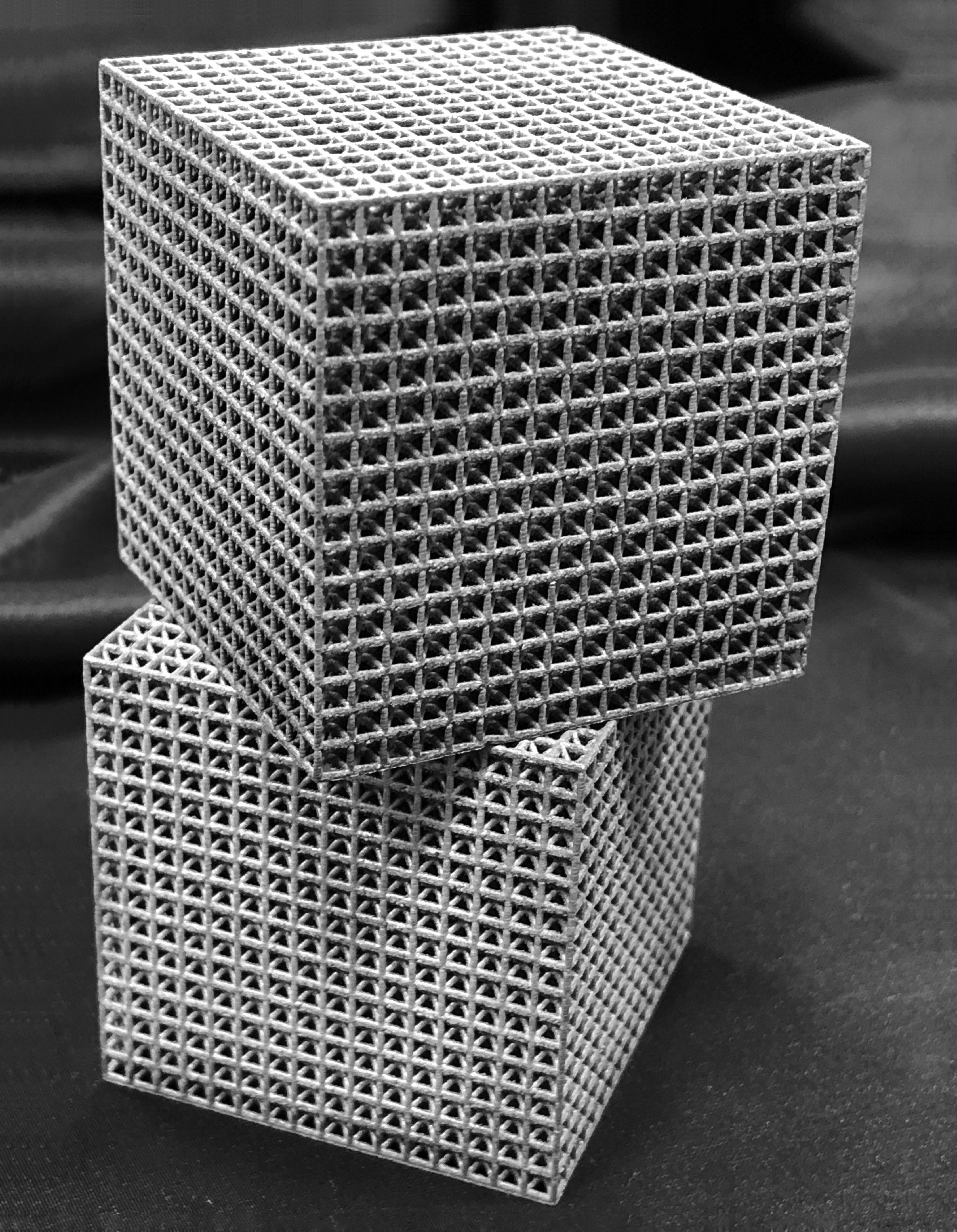
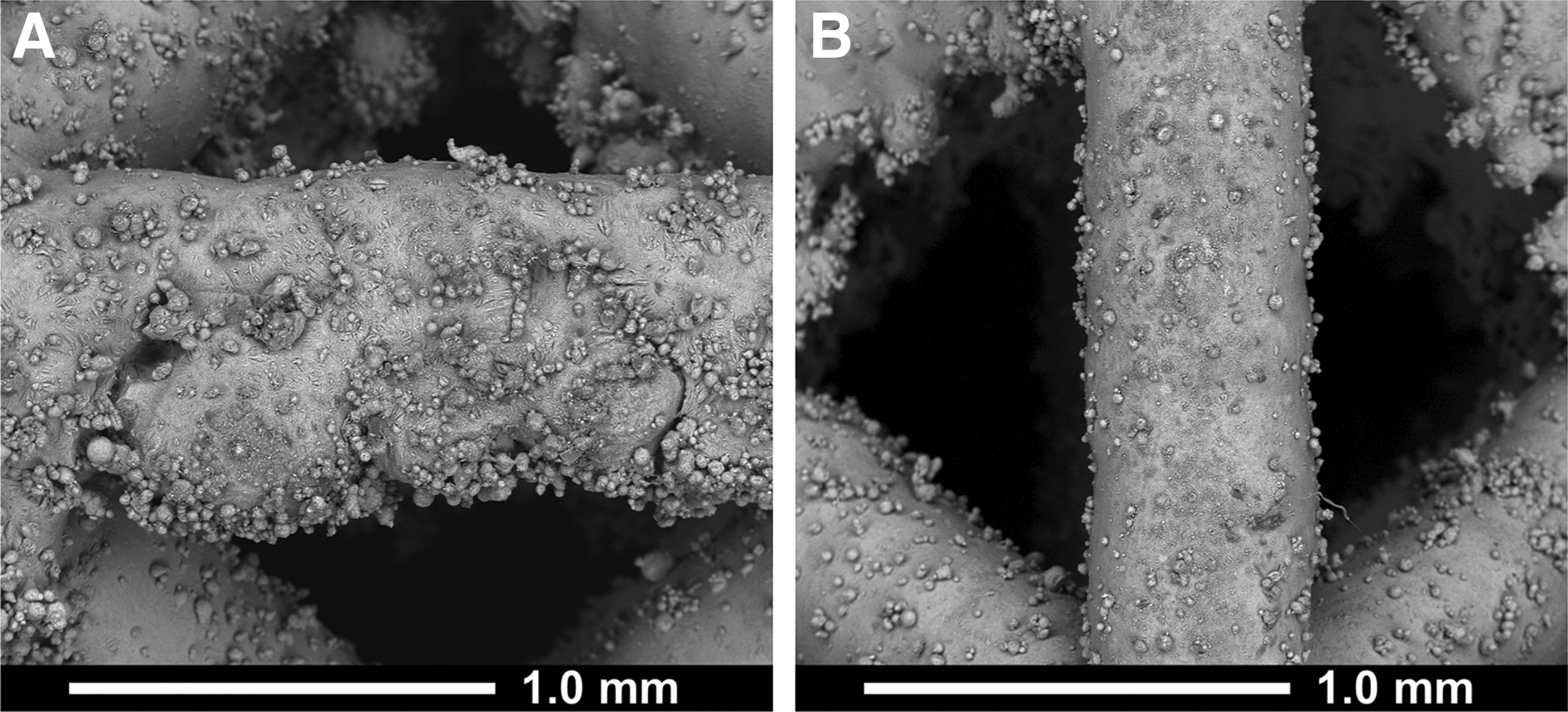
As shown in Figure 2, the 3.4, 3.3, and 3.2 lattice materials were successfully manufactured. The 3.1 samples were instead highly defective. The geometry was not completely reproduced and parts of the struts were not connected. In more detail, the horizontal struts (Sx, Sy: perpendicular to the growth direction) were often incomplete, whereas the printing reliability was higher for vertical struts (Sz: parallel to the growth direction) and for diagonal struts (Sxyz: inclined at 35.26°). The 3.05 specimens resulted in a job failure as struts of 0.30 mm diameter were too thin to be printed. With a nominal beam focus diameter of 80–115 μm, the SLM 500 machine theoretically allows for a minimum feature size of 150 μm, which is smaller, but already comparable with the strut diameter of the proposed 3.05 lattice materials. On the other hand, it is known that besides the laser spot diameter, the particle size of the feedstock powder and other processing parameters such as the laser power and scanning speed may also affect the minimal strut size. 1 As long as the 3.05 group of samples could not be printed, it was thus disregarded in the subsequent discussion.
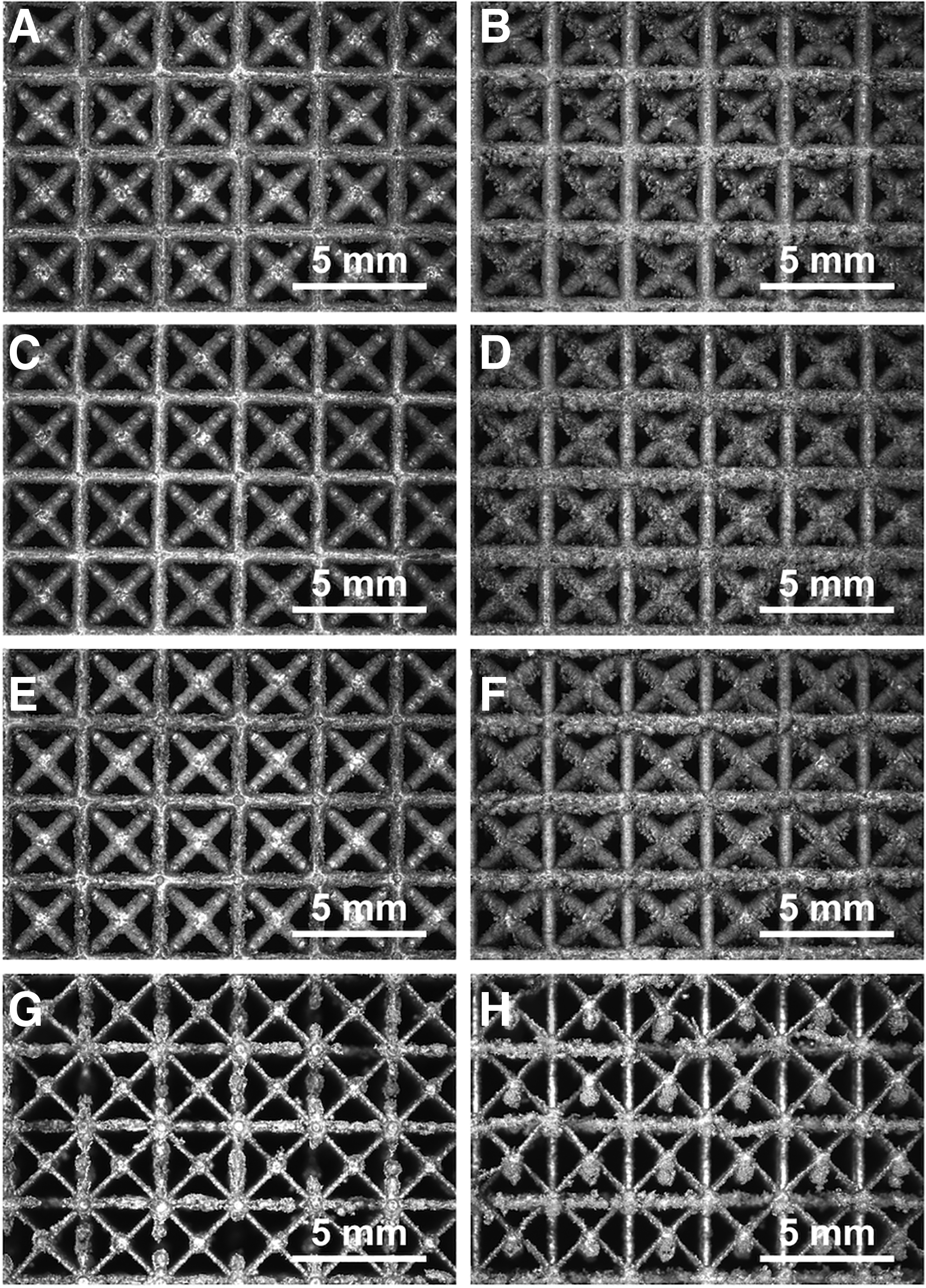
Stereomicroscope images of lattice materials: 3.4 (top,
Relative density
Table 2 reports the experimental relative density of lattice materials and compares it with the nominal values. For relatively dense lattices, the experimental relative density was lower than the nominal one, but the discrepancy was reduced from the 3.4 group of samples to the 3.3 one and was inverted for the 3.2 one. For the 3.1 group, the trend was opposite again since the experimental relative density was lower than the nominal one. However, since the geometry of these samples was incomplete, their volume was approximated to the circumscribed prism and therefore the experimental nominal density was underestimated. In general, data referring to the 3.1 group of samples should be considered with great caution due to the extreme difficulty in obtaining accurate experimental results.
Morphology and geometric accuracy
The graphs in Figure 3 show the diameter values of the various struts as determined from the analysis of calibrated images.
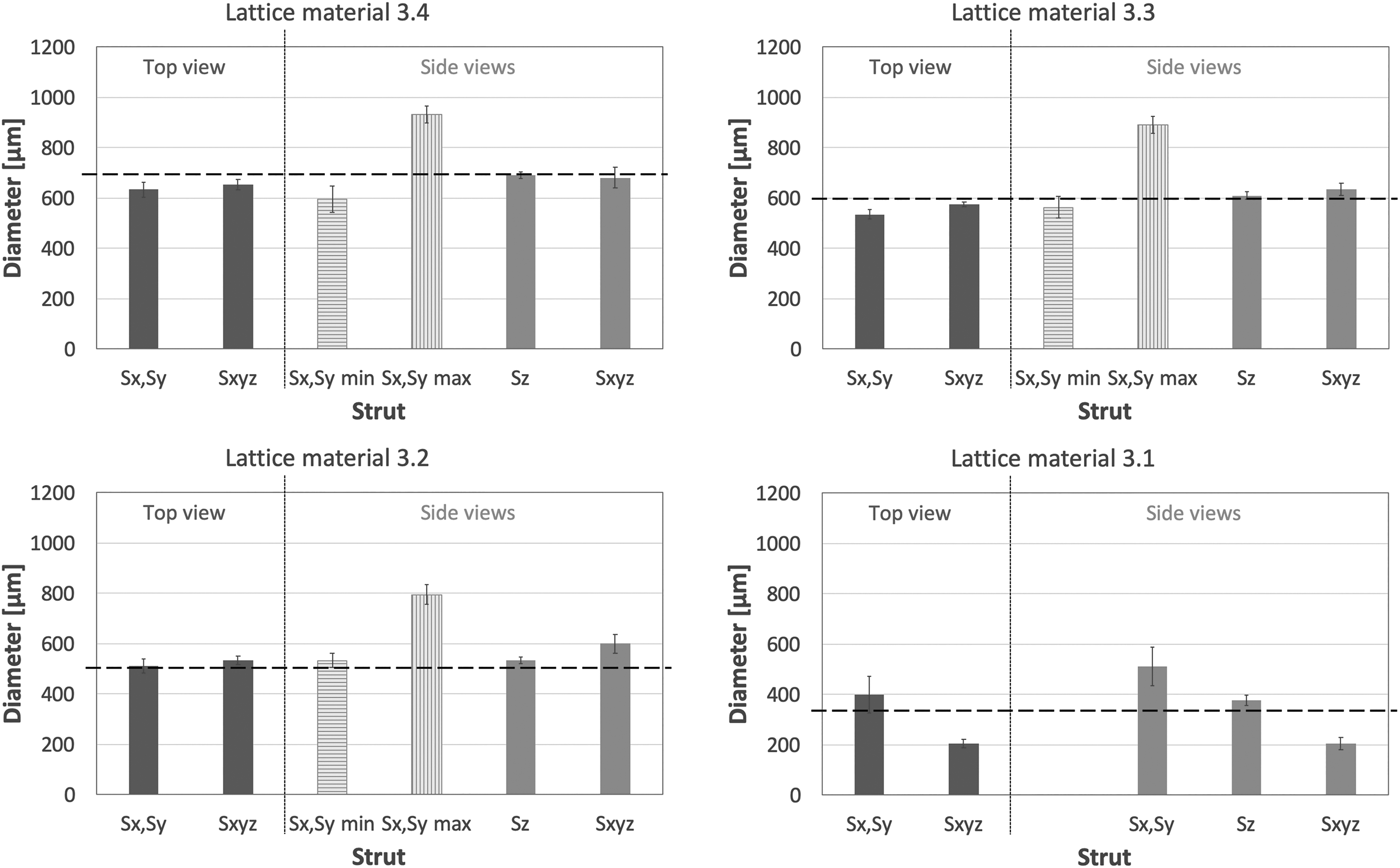
Size of the struts for different lattice materials. Dashed lines represent nominal diameter values.
Using the same symbols as in Figure 1, in the top view of each lattice material, the horizontal struts (i.e., the struts parallel to the build platform, Sx and Sy) had comparable diameter values independently of their specific orientation. For this reason, an inclusive average value was calculated that accounted for all the horizontal struts. It is indicated as Sx, Sy in Figure 3. The diagonal struts are labeled Sxyz. Analogously, for all lattice materials, the horizontal struts had a comparable diameter value on the two side views and therefore an inclusive average value was considered, which is indicated as Sx, Sy in Figure 3. For the same reason, inclusive average values were calculated on the two side views for the vertical struts and for the diagonal ones, which were named Sz and Sxyz, respectively.
If horizontal struts on the side views are considered, it is worth noting that vertical cracks frequently propagated from the downskin surfaces, thus reducing the effective load-bearing cross section. This effect was due to breakdown of the melt track in the first layers that were printed on the loose powder directly. In the subsequent layers, the melt tracks became continuous, but the overall effect was that of cracks extending for nearly half of the strut thickness. Details are reported in Figure 4a. The maximum diameter determines the volume of the strut and hence the mass and density of the lattice material, whereas the residual diameter in correspondence with a crack governs the load-bearing cross section of the strut and hence the mechanical resistance of the lattice material. On account of the relevance of both values, for the 3.4, 3.3, and 3.2 samples, both the maximum diameter and the cracked one were measured and reported in Figure 3 as Sx, Sy max and Sx, Sy min, respectively. For the 3.1 lattice materials, the greatest part of the struts of the outermost cells was broken and therefore the diameter values were measured on the second series of cells. Moreover, since many horizontal struts were structurally interrupted, only the mean diameter (Sx, Sy in Fig. 3) was measured. As a benchmark, the graphs in Figure 3 also show the theoretical strut diameter, which is represented by the horizontal dashed line.
SEM images of horizontal
It can be seen that apart from the maximum diameter of the horizontal struts on the side views (Sx, Sy max), all the struts of the 3.4 and 3.3 samples were thinner than expected, which matched the discrepancy between the experimental and nominal relative densities already observed in Table 2.
Likewise, all the struts of the 3.2 samples were thicker than the corresponding nominal values, which explains why the experimental relative density was higher than the designed one (Table 2). Nevertheless, this overall more bulky structure did not turn into stronger parts as a result of the aforementioned cracks propagating from the downskin surfaces.
As for the 3.1 samples, reaching definitive conclusions is not possible due to the difficulty in measuring their characteristic dimensions. However, as a general trend, it can be observed that the horizontal struts (Fig. 5a) were thicker than the modeled ones, but they were often discontinuous, which was the consequence of thin overhanging parts built without supports. On the contrary, the struts inclined at 35.26° (Sxyz) were built successfully, but with a much smaller diameter than the nominal value (Fig. 5b). Only the diameter of the vertical struts (Sz) was very close to the theoretical value (Fig. 5c). This is consistent with previous observations since vertical struts were systematically built with great accuracy independently of their nominal diameter for all the lattice materials under investigation, as also shown in Figure 4b.
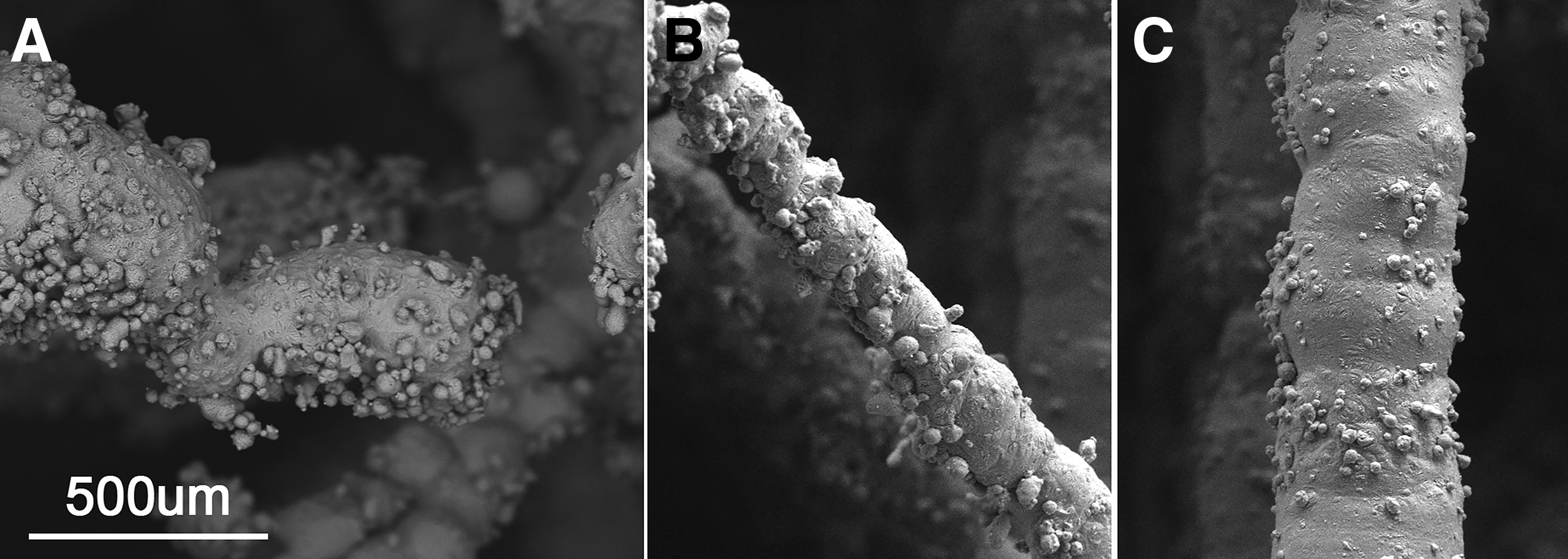
SEM images of horizontal
Discussion
AM and lattice structures are based on the same philosophy: putting material only where it is really needed. In spite of this close correspondence, producing lattice materials by AM is not straightforward. The first issue to face is the relatively limited number of software tools that are currently available to support the design of lattice structures. These software packages additionally suffer from several limitations, including scarce flexibility in merging lattice structures with objects, poor selection of unit cell types, lack of integration with codes for finite element simulations, and poor optimization capabilities. 11
The design of a lattice structure can be accomplished either by tessellation of a manually generated unit cell or by implementation of a mathematically generated periodical pattern. A manually generated unit cell is based on beam or truss structures that are mutually connected through joints that are modified to watertight connections. Mathematically generated motifs are not only less intuitive but also less troublesome because they are often generated as periodic structures that do not need postprocessing to be connected. 11 Through mathematical algorithms, also topological optimization can be applied to design special unit cells, where material is distributed only where it is needed. 1
The BCCXYZ cell (Fig. 1) is an example of a manually generated structure. It was chosen because the greatest parts of the unit cells currently described in the literature belong to the manually created family 11 and hence investigating the feasibility of such structures is particularly relevant. On the other hand, the BCCXYZ cell is especially problematic due to the orientation of the struts and bridging parts, and therefore it is a significant case study. Various cell topologies can be encountered in the literature, 29 but published data regarding this specific type of cell are almost absent since it is extremely difficult to be manufactured. The presence of horizontal beams involves some hurdles in the PBF process. The horizontal beams are overhangs that would need supports and are instead built on loose powder. These bridges are critical areas, whose length can under no circumstances exceed few millimeters. Even so, their successful build is jeopardized by two aspects: (1) in the absence of a supporting structure, they may lift and exit the powder bed due to shrinkage phenomena; and (2) the recoater may exert excessive shear stress and cause their deformation or even failure. The two phenomena are obviously correlated since lifting makes the impact with the recoater unavoidable.
In the present contribution, the build orientation chosen for lattice structures is the one shown in Figure 1, where the Sz struts were parallel to the growth direction. According to this build orientation, the most critical struts were those parallel to the base platform (Sx and Sy in Fig. 1). Upon changing the orientation, the cube edges are expected to become less critical because they depart from horizontality. As a disadvantage, it is also expected that some of the diagonal struts (Sxyz in Fig. 1) become parallel to the base platform. However, in this scenario, the overall percentage of struts that are critical would be lower than in the orientation considered in Figure 1, where eight edges are horizontal. In addition, bridges would become shorter. The layout in Figure 1 represents therefore a worst case in terms of feasibility by L-PBF.
When printing lattice materials, an additional technological hurdle to manage is the intensive memory occupation of .STL files. For the lattice materials considered here, since each cube was made up of a great number of unit cells (163), a massive number of triangles were created to ensure appropriate resolution. As detailed in Table 2, all the resulting .STL files systematically exceeded 500 MB and required powerful computing systems. Similar problems have already been reported in the literature, and nowadays, alternative solutions to .STL files are being developed such as additive manufacturing files (.AMF), which rely upon curved elements and hence use fewer triangles, and new algorithms based on the octree data structure. 3
Aluminum and aluminum alloys offer fundamental advantages, including very low density, high specific mechanical properties such as strength-to-weight ratio, optimal thermal diffusivity, and good electrical conductivity, and excellent corrosion resistance. Aluminum-based systems are therefore the ideal candidates for production of lattice materials by AM in a wide range of industrial applications, such as automotive and aerospace vehicles, high-performance thermal components, and electrical conductors. 29 Nonetheless, research in the field is still very limited, probably due to the intrinsic complexity of laser-processing aluminum-based feedstock powders,30,31 which (in this case) sums up to the aforementioned technical obstacles with cellular structures.
In spite of all these technical hurdles, A357.0 lattice materials could be successfully built with relative density values as low as 20% (Fig. 2). Nonetheless, it could be observed (Fig. 3) that the printing accuracy progressively decreased as the strut orientation approached horizontality (Figs. 4 and 5). Partially molten and satellite particles were likely to adhere to the surface of horizontal struts, especially to their downskin surface. 29 These attached particles did not increase the load-bearing cross section of struts and therefore they did not contribute to the mechanical properties. However, they added to the mass and hence to the experimental relative density of the lattice material. This effect was particularly relevant for slender architectures, such as in the 3.2 group, because the volume of the attached particles was comparable with the volume of the struts.
It is interesting to note that Leary et al. 29 analyzed the producibility of AlSi12Mg lattice materials by L-PBF and reported that for 7.5-mm-wide cubic cells, horizontal struts were never feasible, although the strut diameter was changed from 0.5 to 3.0 mm. To account for the different length of the cell edge, a normalized (dimensionless) strut diameter, φ, can be defined as the strut diameter-to-cell length ratio. Leary et al. 29 considered therefore values of φ that ranged from 0.07 to 0.42 and stated that none of them could be successfully printed with a 0° inclination. The present research focused on values of φ that varied between 0.10 and 0.23 and revealed that if A357.0 powders are processed under optimized parameters, support-free horizontal struts can be successfully printed for φ values as low as 0.17.
Besides the build angle, other variables also should be considered as long as the feasibility of the struts and the morphological differences occurring between the target geometry and the real lattice material may depend on several concurrent reasons. In fact, as previously mentioned, in L-PBF, the strut thickness is influenced by the properties of the feedstock powder and processing conditions. 1
To the best of the authors' knowledge, this is the first time that the BCCXYZ cell could be successfully produced by L-PBF of metals.
Conclusions
As a conclusion, A357.0 BCCXYZ lattice materials were proven feasible by L-PBF down to relative density values of 20% and to a strut diameter-to-cell length ratio as low as 0.17. An upper lightweighting limit of 80% could be reached successfully for a cell dimension of 3 mm. Although this value was specifically measured for the chosen BCCXYZ unit cell, which was built with the vertical edges parallel to the growth direction to account for the worst orientation in terms of printability by L-PBF, this outcome represents an important advancement because it widens the manufacturability range of cell geometries even in the presence of thin overhanging parts to be built without supports.
Footnotes
Acknowledgments
The authors would like to acknowledge ZARE S.r.l. for the technical support and Nikon Instruments Spa for the setup of the laboratory
Author Disclosure Statement
No competing financial interests exist.
Funding Information
No funding was received for this article.