
Abstract
Although continuous projection Stereolithography (SL) printing is one of the next-generation ultra-fast additive manufacturing (AM) processes, its current constrained window design of the resin vat is suffering from many challenges, such as the complex control mechanism and limited hardware lifetime. In this article, we investigate a novel constrained window design, namely Island Window (IW), for the continuous three-dimensional (3D) printing by using the projection SL process. The proposed IW window has a highly oxygen-permeable polydimethylsiloxane membrane onto the laser-machined acrylic vat frame, which allows the formation of an effective liquid interface (>200 μm oxygen inhibition layer) to enable the continuous projection SL process. Experimental results verified the feasibility of the window design for extending the maximum printing time (increased by up to 73%) due to the enhanced oxygen concentration. It was also found that the maximum printing speed for producing parts with a smooth surface (Rz <30 μm) can be as high as 90 mm/h, which is comparable to the speeds in recently reported continuous SL processes. In addition, a variety of parts were successfully fabricated through continuous 3D printing by using the proposed IW design, implying tremendous promise for future low-cost, high-resolution, easy-controlled, and ultra-fast AM processes.

Introduction
Additive manufacturing (AM) provides a promising fabrication solution to rapidly prototype products with complex geometries, which are usually challenging with conventional manufacturing approaches.1–5 Various AM processes have been developed for a diverse range of materials, including metals, polymers, ceramics, and composites.6–10 Stereolithography (SL) is one of these AM techniques for fabricating three-dimensional (3D) objects by using photosensitive polymers.11–13 The process usually builds parts in a layer-by-layer way through stacking solidified two-dimensional (2D) layers.14–16 Each layer gets polymerized by light exposure using digital mask images. Recently, non-layer-based projection SL methods, including CNC accumulation, Continuous Liquid Interface Production (CLIP), High-Area Rapid Printing (HARP), and Mask Video Projection-based SL (MVP-SL), have been demonstrated.17–20 Different from the conventional layer-by-layer approaches, the part is continuously pulled out from the liquid resin when projecting a sequence of sliced images seamlessly (slice video). The building speed of such continuous printing processes can be an order of magnitude faster than the traditional layer-by-layer approaches, and the “staircase effect” typically found in the layer-by-layer structure can be eliminated.
In such continuous printing processes, the liquid interface (a layer of uncured liquid resin between the platform and the resin vat) is critical, which enables the easy separation of the curing part from the constrained window, as shown in Figure 1. This liquid interface can be created by methods, including oxygen inhibition and continuous liquid refilling. For instance, a highly oxygen-permeable window (100 μm thick Teflon film) was used in the CLIP process for continuously supplying oxygen to maintain the liquid interface. 17 The initial thickness of the oxygen inhibition layer in such processes can be up to 120 μm, which also provides room for rapidly replenishing the resin under the building platform during the continuous curing and separating. Despite benefits of the thin and air-permeable Teflon film, some common issues, including film tensioning failures and creases on the film, have been reported.21–23

Illustration of continuous printing with the oxygen-permeable window.
In addition to improving the air diffusion by using a highly air-permeable material as the constrained window, enabling continuous liquid flow is another approach to create the liquid interface for continuous 3D printing. For example, a continuous fluorinated oil flow between the constrained window and the liquid resin in the HARP process facilitates the easy separation of the curing part. 19 It is capable of fabricating hollow structures with large areas (e.g., 30 cm by 30 cm) at an ultra-fast printing speed (432 mm/h). However, the surface roughness of the printed parts may be highly affected by the oil flow. An alternative method to build the continuous flow is to integrate additional robotic systems. As demonstrated by the MVP-SL process, an extra linear stage was integrated to achieve a continuous horizontal movement of the resin vat to enhance the resin refilling for creating the liquid interface in a relatively large vat. 20 To accommodate the second-stage motions, the control mechanism of MVP-SL is complex, which could involve unstable resin flow and affect the surface finish. It should be noted that the constrained window in MVP-SL is the conventional polydimethylsiloxane (PDMS) coated glass plate. This PDMS/glass-layered constrained surface provides both rigidity and elasticity, eliminating the needs of film tensioning and mechanical clamping. In addition, the relatively thick (1–2 mm) PDMS film coated on the rigid glass plate is resistant to creasing.
Although PDMS is a commonly used inexpensive and reliable material for preparing constrained windows for the layer-by-layer photopolymerization AM process,24,25 the oxygen permeability of PDMS is significantly weaker than the Teflon film. The oxygen permeability of PDMS is ∼300 barrers, whereas the Teflon film has a 1000 barrers oxygen permeability.17,26 On the other hand, as demonstrated in the MVP-SL process, due to the high elasticity of PDMS, it is typically equipped with rigid and transparent materials such as glass or acrylic for the use in the SL process. The downside is that integrating plain glass/acrylic degrades the oxygen permeability of the window. According to Dendukuri et al., the thickness of the oxygen inhibition layer provided by the PDMS/glass structure is only ∼2.5 μm, which is insufficient for continuous SL processes. 27 To enhance the oxygen permeability of PDMS-based materials, methods such as adding external oxygen supply and modifying PDMS composition have been investigated for enhancing the oxygen permeability.28–30 The addition of external devices makes the printing system bulky, whereas changing the PDMS composition would degrade the tensile properties. Researchers have also investigated patterned surface designs by creating microscale patterns on the vat for air diffusion in the layer-by-layer SL process. 31 The printed structure might suffer from undesired textures caused by the microscale patterns and off-centered light reflection.
Considering the limited number of continuous 3D printing approaches and the critical role of the constrained window, it is of great importance to investigate alternative designs of the constrained window for continuous 3D printing. In this article, we investigate a novel constrained window design, namely Island Window (IW), for the continuous 3D printing by using the projection SL process. The proposed IW window consists of a highly oxygen-permeable PDMS membrane and a laser-machined acrylic vat frame. This PDMS/acrylic layered structure allows the formation of a liquid interface to enable a reliable continuous projection SL process. We investigate the effectiveness of the window on extending the continuous printing time. The maximum printing speed of the proposed IW design is also characterized. In addition, a variety of parts were successfully fabricated through continuous 3D printing by using this IW design, implying tremendous promise for future low-cost, high-resolution, and ultra-fast AM processes.
Materials and Methods
In this study, a projection SL setup with the IW-based resin vat was developed for continuous 3D printing, as illustrated in Figure 2a. It consists of an imaging unit (Wintech PRO4500; Texas Instruments), an acrylic platform, a linear stage (MN10; Velmex), and a liquid resin vat with the proposed IW bottom. The vat in the proposed Island design has an acrylic vat frame and a coated PDMS membrane. The acrylic vat frame mainly provides the rigidity to the vat, and the coated PDMS membrane is the substrate for the continuous SL process. Different from conventional PDMS/acrylic constrained window designs, this Island constrained window is a square-shaped surface (side length A) consisting of two regions, the island region and the air-diffusion region, as shown in Figure 2b. The island region (side length B) in the surface center is connected with the vat boundaries by four strips with width C. The rigid island region is used for polymerizing liquid resin, whereas the air diffusion region is responsible for supplying oxygen to form the liquid interface onto the printing area. The proposed IW design is geometrically characterized by the ratio between the area of the air diffusion regions and the area of island region α, which is defined by Equation (1). Various α were investigated for the oxygen inhibition layer, the separation force, and the corresponding continuous printing capability.
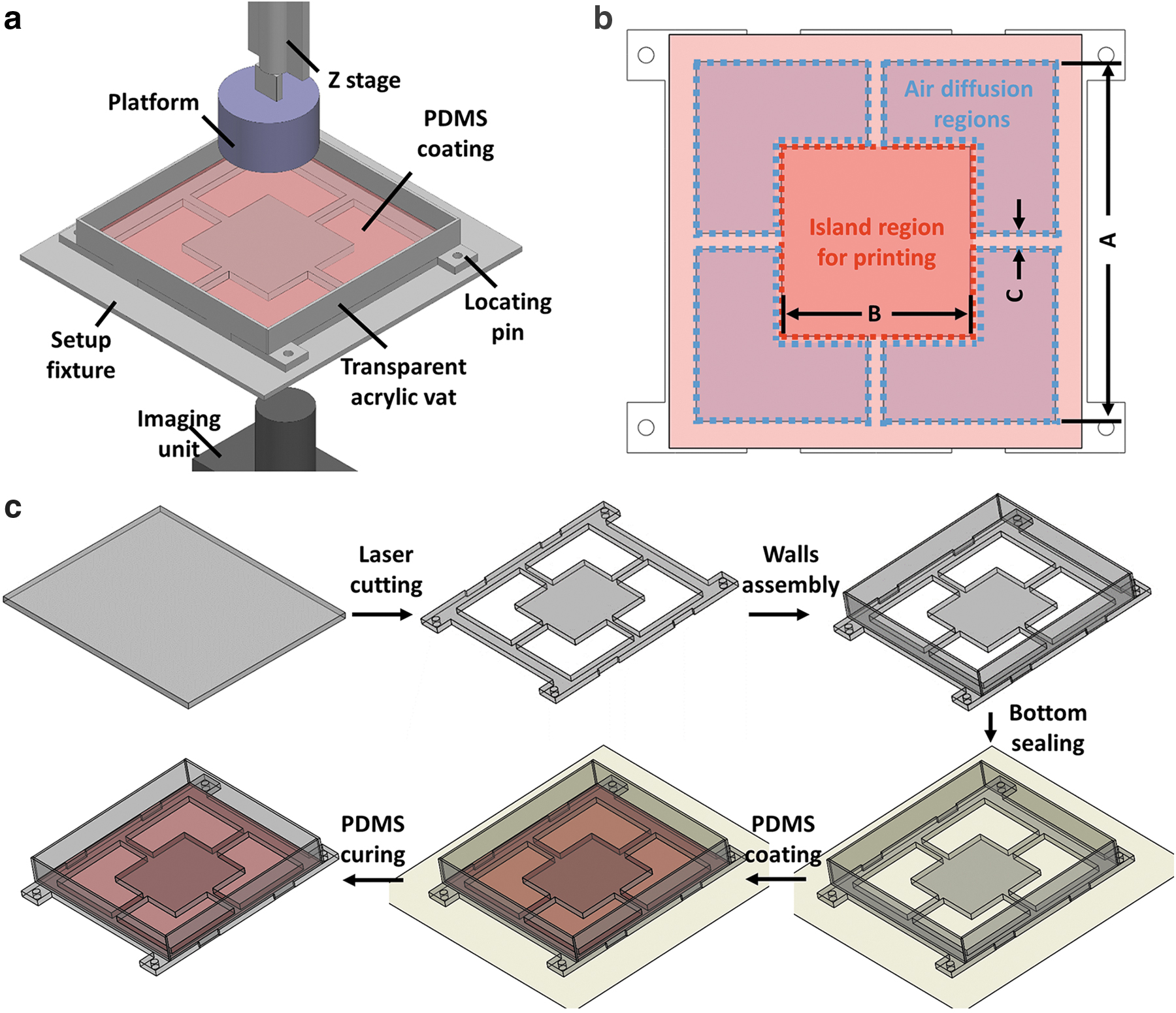
IW window design.
In the following discussion, the bottom surface side length A is 100 mm, and the strip width C is 5 mm. The calculated corresponding side length of the island region with α ranges from 3 to 7, as shown in Table 1.
Calculated Island Region Geometries (A = 100 mm, C = 5 mm)
To fabricate this proposed liquid resin vat, an acrylic plate (4.76 mm thickness; McMaster-Carr) was first cut by a laser cutting machine (Universal Laser Systems, USA) to create the air diffusion regions, as shown in Figure 2c. Then, vat walls were tightly assembled before sealing the bottom by a flat surface. The PDMS was prepared by mixing the base material and curing agent with a 10:1 weight ratio, using a conditioning mixer (AR100; Thinky) at 2000 rpm for 3 min, followed by 3 min of centrifugation. Then, the uncured PDMS mixture was added into the vat to form a 2.0 mm-thick coating on top of the acrylic plate (island region). The entire vat with PDMS liquid was dried at room temperature for 72 h to allow the PDMS to completely solidify. Compared with CLIP and MVP-SL approaches, our proposed IW design does not require the film tensioning process and only needs a single Z stage, which is beneficial for avoiding surface creases and minimizing unstable resin flow. In the following sections, we will discuss the oxygen concentration and the separation dynamics during the continuous printing process.
Results and Discussion
Oxygen inhibition layer
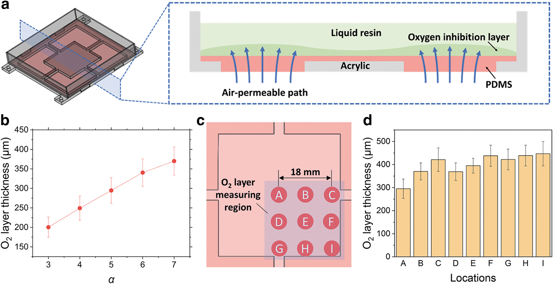
Figure 3a shows the cross-sectional view of the fully fabricated vat in the IW design to illustrate the oxygen permeation path. In the proposed IW design, the bottom acrylic plate barely has air permeability, whereas PDMS exhibits a relatively good air permeability with many reported applications.29,30,32 The oxygen passes from the ambient environment through the PDMS, and it then reaches the center of the resin vat to create the liquid interface (oxygen inhibition layer).
Oxygen inhibition layer.
To investigate the influence of the design parameter α on the oxygen permeability, the thickness of the oxygen inhibition layer in the liquid interface was characterized. The liquid photopolymer used in this test was MakerJuice Labs Standard. Island designs with α range from 3 to 7 were first tested at the center location of the island region. Herein, a differential approach was used to estimate the oxygen inhibition layer thickness, in which the liquid photopolymer was sandwiched between the constrained window and an impermeable glass with two 500 μm-thick brass shims supporting them. 33 A UV imaging unit (135 ± 5 mJ/s light intensity and 405 nm wavelength) projected a 5 mm-diameter light beam for 30 s. It should be noted that the 30 s is adequate to fully solidify the tested resin according to the resin specifications. After light projecting, a cylinder structure with a 5 mm base diameter was gradually fabricated. The corresponding oxygen inhibition layer thickness was obtained by differentiating the cured cylinder thickness from the shim thickness (500 μm). The IW design geometries with various α ranging from 3 (2372 mm2) to 7 (1168 mm2) were characterized. As shown in Figure 3b, the thickness of the oxygen inhibition layer at the center of the Island design ranges from 200 to 370 μm when α increases from 3 to 7, and the correlation is approximately positive linear. The findings indicated that a larger island region area resulted in less oxygen diffusion. In addition, according to the measurements at the center location, the air permeability of the IW window is comparable to the highly oxygen-permeable Teflon film AF 2400 used in the CLIP process, 17 revealing the feasibility of the proposed design on enhancing the oxygen concentration.
Afterward, we studied the distribution of the oxygen concentration on the entire Island region. As illustrated in Figure 3c, considering the symmetry of the design, several locations uniformly arranged at the right-bottom part of the island region (α = 5, B = 39.57 mm) of the resin vat were measured by using the aforementioned differential method. The measurements were then summarized in Figure 3d. For the IW design with α = 5, it showed that the center (A) of the island has an oxygen inhibition layer thickness of 296 μm, and it rapidly increases to a thickness of 447 μm on the printing area boundary. It indicated that the oxygen concentration is distributed on the island region with the lowest oxygen concentration at the vat center. Although the distribution of the oxygen is not uniform, the overall adequate oxygen concentration (>250 μm oxygen inhibition layer) on the entire Island region is capable of creating an effective liquid interface for the easy separation during the continuous pulling.
Separation dynamics and printability
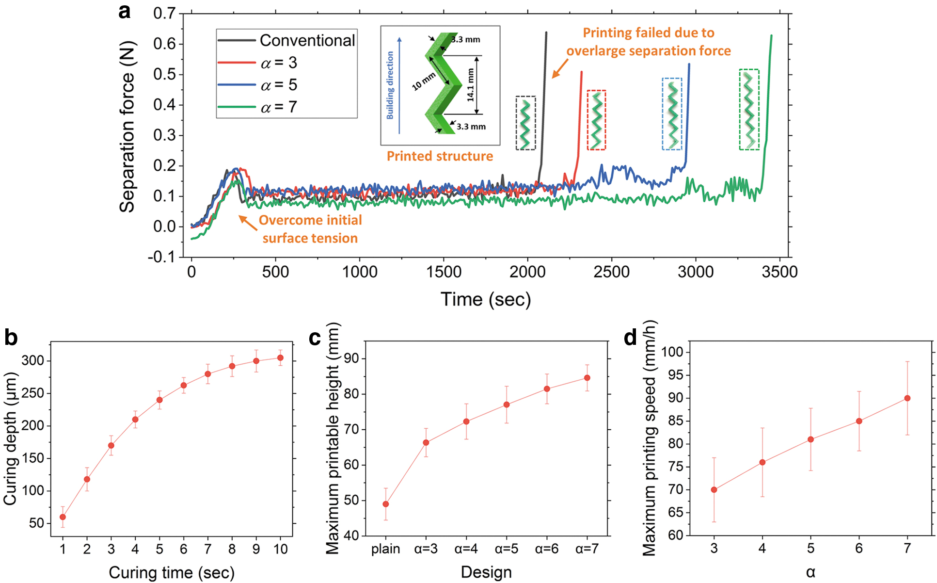
In this section, we further investigated the influence of the liquid interface in IW designs on the separation dynamics and the printability. In the continuous printing process, it is essential to match the printing speed to the photopolymer curing speed to maintain the liquid interface. Otherwise, printing defects such as over-curing (printing too slow) and weak bonding (printing too fast) may occur. In our study, the time-dependent curing depth of the liquid resin was characterized, as shown in Figure 4b. It was obtained by first projecting a 5 mm-diameter light (135 ± 5 mJ/s light intensity and 405 nm wavelength) with a varied light exposure time in the range of 1 to 10 s. Afterward, the corresponding thicknesses of the cured part (cylinder) were measured by using a micrometer. Results indicated that the curing depth increases from 60 to 300 μm when the projecting time increases from 1 to 10 s, which gives an ∼70 mm/h estimated curing speed of the tested resin. In the following discussion, we set the printing speed at the range from 50% to 150% of the estimated resin curing speed, to further investigate the separation and printability.
Separation dynamics and printability.
To study the capability of the design on extending the effective printing time (the printing time before any overlarge separation force happens), a successive “<” structure without height limit was tested. The cross-section of this “<” structure is a 3.3 mm by 3.3 mm square. The CAD of the tested structure and photos of printed models are included in Figure 4a. We tested continuous printing by using both conventional design (no air diffusion region) and IW designs with α = 3, 5, and 7 at a consistent 90 mm/h printing speed. The corresponding separation forces were recorded by using a force-detection system. 16 The system consisted of a load cell (LRM 200; Futek) and a data acquisition (DAQ) device (USB 6008; National Instruments). The real-time separation force was monitored in the integrated Matlab/Simulink unit.
As shown in Figure 4a, the separation force of the continuous printing exhibits a similar trend consisting of three distinct phases, namely the initial, stable, and end phase. The initial phase usually occurred within the first 500 s of the printing. The separation force in this phase slightly increased to 0.2 N to overcome the surface tension of the liquid resin in the resin vat. After sufficient Z stage movement, the surface tension became inconsequential, and the separation force decreased and stabilized at ∼0.1 N for continuous printing (stable phase). In the stable phase, the oxygen was gradually and consistently consumed for inhibiting the photopolymerization, because the oxygen permeation was slower than the oxygen consumption in the photopolymerization process. The variations of the separation force in this phase were usually minimal, and the part can be continuously printed. However, once the oxygen concentration decreased below a threshold, the separation force significantly increased to more than 0.5 N (end phase). In the end phase, the excessive separation force can lead to printing failures and defects, including weak bonding and over-curing. In short, the effective printing time of conventional design and IW designs ranged from 0.55 to 0.95 h. The conventional design has the shortest effective printing time (0.55 h) due to the very limited oxygen concentration in the liquid interface. When the IW design was implemented, the working time increased to 0.63, 0.81, and 0.95 h when α = 3, 5, and 7, respectively. The effective printing time is linearly dependent on the initial oxygen inhibition layer thickness. The improvement in the effective printing time (increased by up to 73%) is due to the increased thickness of the oxygen inhibition layer (proportional to α). In addition, the proposed IW design also enables a significant increase (from 49 to 84 mm) in maximum printable height (Fig. 4c).
To understand the effect of design parameter α and printing speed on the printed surface finish, the maximum printing speed for producing models with a smooth surface was characterized by using the same “<” structure. The maximum printing speed was defined as the printing speed that produces a surface finish less than 30 μm ten-point mean roughness (Rz). The surface quality of printed parts was characterized by a surface roughness tester (GT-K Optical Profiler, Bruker). The maximum printing speed of IW designs with α ranging from 3 to 7 is shown in Figure 4d. The maximum printing speed increased slightly from 70 to 90 mm/h, indicating that a larger thickness of the created oxygen inhibition layer is also helpful for speeding up the printing process while producing a good surface finish. As summarized in Table 2, we made a comparison between existing constrained window designs for continuous SL processes and the proposed IW design. The comparison includes the basic constrained window components, the complexity of the system, the maximum printing speed, and the liquid interface type. Our proposed IW design exhibits a low-cost hardware structure with a competitive printing speed and simple flow controls; we believe that the IW design can be an alternative approach for future ultra-fast continuous SL processes.
Constrained Window Designs in Continuous Stereolithography Processes
Single-head printing, relatively slow speed.
Solid parts thinner than 2.0 mm.
n/a, not available; PDMS, polydimethylsiloxane.
Using the proposed IW designs, complicated 3D geometries were continuously printed. Some test cases are shown in Figure 5. The 60 mm-tall artichoke model (Fig. 5a) was printed at 70 mm/h by using α = 5 design (39.57 mm square island region) with a fine surface finish. Figure 5b demonstrates a hollow-structured turbo shell model (32 mm bottom side length, 30 mm tall) printed at 60 mm/h speed by using α = 5 design. The vase model shown in Figure 5c is 70 mm tall, and it was printed at 60 mm/h by using α = 6 design (36.58 mm square island region). Figure 5d shows a cage model (22 cm diameter) printed at 80 mm/h speed by using α = 7 design (34.17 mm square island region) due to the relatively small model cross-section. All these continuously printed parts exhibit an excellent surface finish (Rz <30 μm). It confirms that the IW design enables continuous printing of 3D complex macroscale geometries with a smooth surface finish, with a fast printing speed.

Printed parts by using the proposed IW design.
Conclusion
In this study, we designed a novel constrained window design, namely IW, for the continuous 3D printing by using the projection SL process. The proposed design had a highly oxygen-permeable PDMS membrane coated onto a laser-machined acrylic vat frame, which allows the formation of an effective liquid interface (>200 μm oxygen inhibition layer) to enable the continuous printing process. Experimental results verified the feasibility of the window design for extending the maximum printing time (increased by up to 73%) due to the enhanced oxygen concentration. It was also found that the maximum printing speed for producing parts with a smooth surface (Rz <30 μm) can be as high as 90 mm/h, which is comparable to the speeds in recently reported continuous SL processes. In addition, a variety of parts were successfully fabricated through continuous 3D printing by using the proposed IW design, implying tremendous promise for future low-cost, high-resolution, easy-controlled, and ultra-fast AM processes.
Footnotes
Acknowledgments
The authors would like to acknowledge the funding of this project. They would like to also acknowledge the Nanotechnology Core Facility (NCF) of the University of Illinois at Chicago campus for the use of the Bruker GT-K Optical Profilometer.
Author Disclosure Statement
No competing financial interests exist.
Funding Information
This work is supported by the National Science Foundation under Grant 1563477.