
Abstract
Electrohydrodynamic jet printing (EJP) is a developing additive manufacture technology that enables the fabrication of fine scaffolds directly from polymer solutions or melt. Timely solidification of the polymer jet is the key factor for the success of EJP process. In conventional solution-based EJP methods, it is usually achieved by rapid solvent evaporation and producing a scaffold with smooth filaments. In current study, by combining solution-based EJP with a cryogenic workbench, a cryogenic electrohydrodynamic jet printing (CEJP) system was developed, in which the polymer jet was frozen and solidified quickly at the freezing temperature rather than solvent evaporation. The feasibility and versatility of the CEJP system were verified by successful printing of scaffolds with different hole shapes and pore sizes. Meanwhile, the resulting scaffolds not only had a resolution in the range of 50–80 μm but also possessed oriented “ridges” and “valleys” on surface of the filaments, which was conductive to cell orientation. Therefore, this work provides a novel method to print fine scaffolds with extra surface topography.
Introduction
Electrohydrodynamic jet printing (EJP) has been explored as a promising method on directly manufacturing fine scaffolds for medical applications. 1 To date, it has been used successfully in fabrication of polymer scaffolds for cartilage, skin, and tendon regeneration research, with feature sizes ranging from a few microns to dozens of micrometers.2–4 According to the materials used, it is usually divided into solution- and melt-based EJP. 5 Its working principle can be seen as an ingenious combination of electrospinning with computer-controlled translational collection, so the fibers can be plotted in additive manufacturing manner. 6 However, in comparison with traditional electrospinning, EJP usually maintains a tip-to-substrate distance at 2–10 mm rather than tens of centimeters.7–9 In such a short distance, to obtain a stable three-dimensional (3D) scaffold, the liquid polymer jet must be solidified timely to ensure the formation of the structure. The melt can be achieved easily by cooling, but the solution mainly depends on the evaporation of solvent. 10 In fact, it is difficult to completely evaporate the solvent during printing, and semifluid polymers often lead to thin scaffolds thickness and poor layer-by-layer deposition, but the solution method has the advantage of being easy to introduce functional molecules and nanomaterials into the printed structure.11–13
Moreover, it is worth noting that the filament surface of printed scaffolds is smooth in both conventional solution- and melt-based EJP.14,15 Several reports have indicated that rough or microscale patterned surfaces were more favorable for cell adhesion and differentiation. For instance, Kumar et al. developed a solvent etching process that produced a rough surface on the struts of free-forming scaffolds to promote cell proliferation and differentiation. 16 Jing et al. introduced a nanoscale shish-kebab coating on the fibrous scaffold by dipping and phase separation to enhance cell adhesion and proliferation. 17 Therefore, it is valuable to develop a method that can not only overcome the limitations related to solvent evaporation but also create surface topography on the fine scaffold filaments printed by the EJP method.
It is still a very challenging task to manufacture fine scaffolds with extra filament surface simultaneously. To address this issue, Ahn et al.18,19 proposed a modified EJP process, in which a poly (ethylene oxide) solution bath was used to replace the traditional grounded substrate to prepare scaffolds with high porosity and surface roughness. Their work was innovative because, with the help of an auxiliary solution, the residual solvents in the deposited jet did not crush the structure as they did on a hard substrate, and a 2 mm thick scaffold was obtained. However, the method was difficult to control the feature size at micron level like the conventional EJP, and the filament diameters basically exceeded 220 μm.
Our previous research proposed a facile method for fabricating superficially porous polycaprolactone (PCL) scaffolds by extrusion-based cryogenic 3D printing (ECP), which used rapid freezing of solvents instead of evaporation. After lyophilization, the additional pattern surface topography was fixed on the filament, which had a better effect on cell adhesion and proliferation, but the resolution of the method was also >200 μm. 20 Low resolution was mainly due to the nature of extrusion-based 3D printing, whose filamentary feature size was usually in the level of several hundred microns. 21 Therefore, the combination of cryogenic platform and solution-based EJP system should be a new method to facilely fabricate scaffolds with high resolution and extra surface topography at the same time.
In this work, according to the ECP platform in our laboratory, a modified EJP was developed by combining solution-based EJP with a cryogenic workbench. To illustrate the novel system, PCL was chosen as the printing polymer and glacial acetic acid (GAC) was used as solvent for its low toxicity and high freezing point (i.e., 16°C). Configurations of the cryogenic electrohydrodynamic jet printing (CEJP) system and the influence of cryogenic temperature were illustrated and checked firstly. Then, a variety of scaffolds with different hole shapes and pore sizes were printed to demonstrated the feasibility and flexibility of the CEJP method. Finally, the specific morphology and cellular response to the fine scaffold were also studied.
Materials and Methods
Printing solution preparation
PCL/GAC printing solution was prepared according to the protocol described in the previous report. 20 Briefly, 40 wt.% PCL was dissolved into GAC by continuous magnetic stirring at 100 rpm for 6 h at 65°C and centrifuged for 2 min to remove air bubbles from the solution. The solution was then loaded into a 5 mL plastic syringe for post-printing experiment.
Development of the cryogenic electrohydrodynamic jetting printing platform
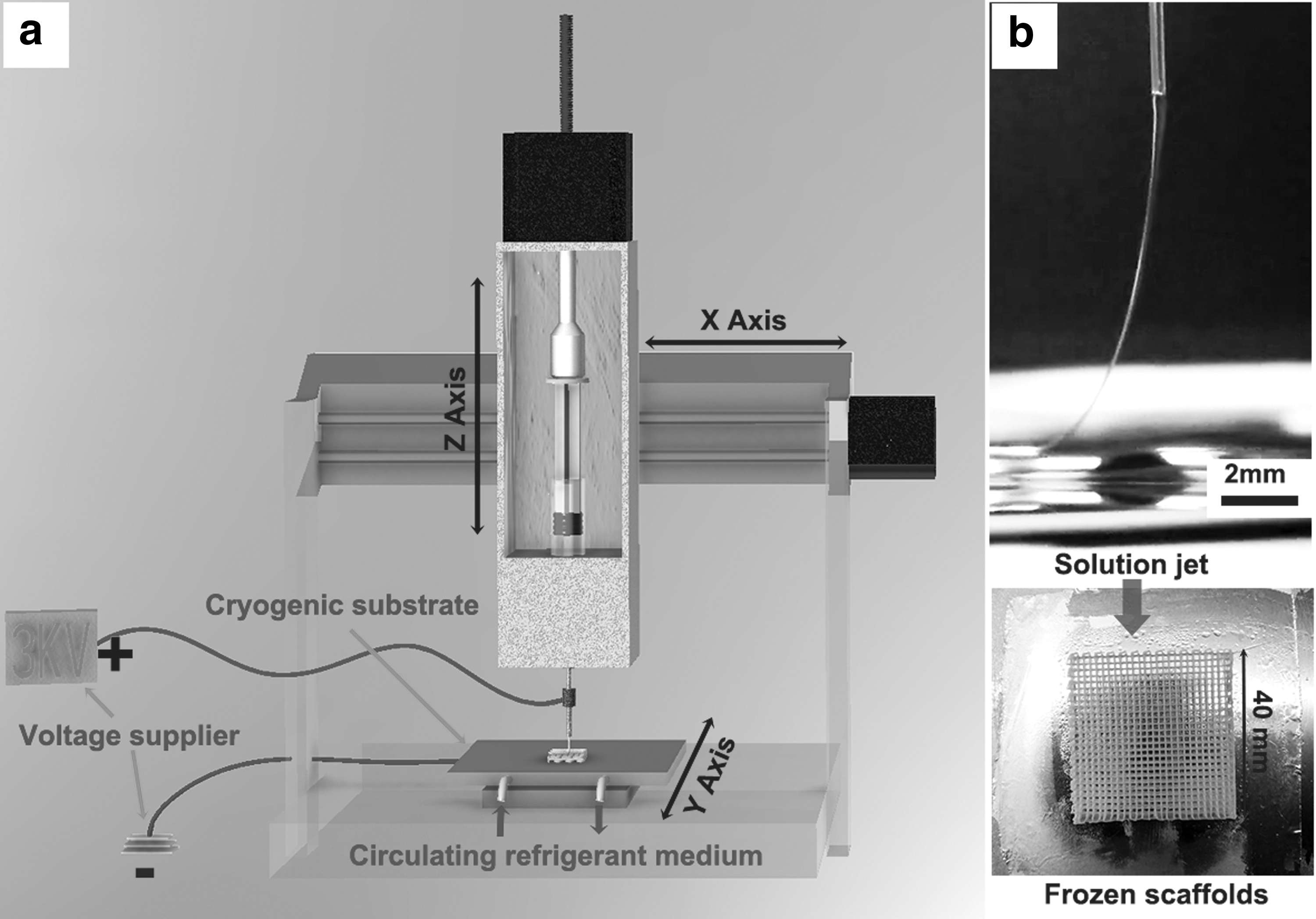
Figure 1a presents a schematic illustration of in-house developed CEJP platform, which was used for printing demonstration in the current study. It contained a high-voltage DC power supply (DWP303-1ACF0; Dongwen High Voltage, Tianjin, China) and a modified commercial 3D printer (MAM-II; Fochif, China) equipped with a customized cryogenic substrate. The cryogenic workbench was controlled by a cryopump (DLSB.5L-40°C; Zhengzhou Teer Equipment Co., Ltd, Zhengzhou, China) to create a stable freezing temperature profile. 22 Before printing, the cryopump was turned on to cool the substrate to −20°C. Then, a 25G (inner × outer diameters: 0.26 × 0.51 mm) metal nozzle was mounted on the plastic syringe with PCL solution and fixed in the extrusion chamber with a piston to adjust the flow rate. Then, the positive power cable was connected to the metal nozzle and the ground wire was fixed to the substrate. During printing, a smooth stainless steel plate was placed on the cryogenic substrate as a collector for scaffold deposition.
Scaffold printing
The traditional EJP works showed that only when the solution jet speed Vj was slightly slower than the collector moving speed Vc, the accurate pattern can be successfully printed. 23 Under this condition, the jet was tail-shaped, as shown in Figure 1b. To maintain the stability of the tail jet, the key parameters must be adjusted to a suitable window. Here, the freezing temperature on the substrate was an independent parameter, and it was set at −20°C. Then, the other related parameters such as the tip-to-collector distance (TCD), supplying voltage, moving speed, and feed rate were fixed at 10 mm, 3 kV, 30 mm·s−1, and 0.5 mL·h−1, respectively. In addition, it was necessary to keep the ambient temperature and humidity at around 20°C and 40%, respectively. After printing, the wet scaffolds with frozen GAC were immediately transferred to a lyophilizer for 36 h to remove the residue solvents and obtain dry scaffolds.
To confirm the feasibility and flexibility of the CEJP platform, several sets of scaffolds with different hole shapes and pore sizes were printed in the process window. For instance, a group of orthogonal network scaffolds with a size of 40 × 40 mm2 and filament offsets of 400, 600, 800, and1000 μm were printed. Scaffolds with oblique and orthogonal oblique pores were also printed.
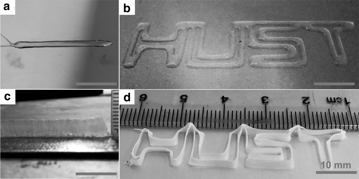
Meanwhile, early experiments of temperature effects on shape retention were performed by printing a line and a logo of the Huazhong University of Science and Technology (HUST) at room and freezing temperatures, respectively.
Morphology analysis and cell adhesion performance
Macromorphology and micromorphology of the printed scaffolds were observed under optical microscope (B011; Supereyes, China) and scanning electron microscope [field emission scanning electron microscopy (FESEM), JSM7600F; JEOL Ltd., Japan], respectively.
Rat bone mesenchymal stem cells (BMSC) cells were selected to evaluate the cellular response to the printed scaffolds. After BMSCs culturing on surface of the scaffold for 3 days, the culture medium was removed and washed with phosphate-buffered saline (PBS) three times. Then, a mixture of propidium iodide (2 × 10⁻³ mM) and calcein-AM (2 × 10⁻³ mM) (Sigma) in 2.0 mL of PBS was applied to stain the cells in an incubator for 15 min, and the scaffolds were subsequently washed with PBS. The cell growth profile was observed by a laser scanning confocal microscope equipped with a digital camera (Nikon A1, Japan). 24
Results and Discussion
Effects of the freezing temperature
One key point for successful electrohydrodynamic printing was the coordination of solution jet speed Vj and collector moving speed Vc. Several works suggested that the tail-shaped jet formed under the condition of Vj slightly lower than Vc can ensure the stable and accurate deposition of polymers.23,25,26 As shown in Figure 1b, during the CEJP process, the tail jet was also necessary for plotting straight filament, and it changed dynamically along the moving path (Supplementary Video S1). If the Vj was equal to or faster than Vc, the deposited jet was easily buckled.27,28 Therefore, all subsequent experiments were performed under the condition of Vj slightly lower than Vc.
Another key point was the freezing temperature, which dedicated to the CEJP method. Unlike the conventional solution-based EJP system, the CEJP platform added a cryogenic substrate to the Y-axis, as shown in Figure 1a. The freezing temperature can be achieved by circulating the refrigerant medium, and according to our previous study on cryogenic 3D printing, −20°C was preferred for regular lattice scaffolds. 20
Here, a preliminary experiment was carried out to verify the effect of freezing temperature by patterning a line and HUST logo at room temperature and −20°C, respectively. At room temperature, both the line and HUST logo were collapsed due to the presence of residual solvents in the deposited jet, which crushed and merged the filaments together during printing, as shown in Figure 2a and b. While, in case of freezing temperature, the line pattern constructed a “wall” structure of height 5 mm under the back and forth plotting, as shown in Figure 2c. Similarly, the constructed HUST logo appeared to be made of a white ribbon standing on the narrow side, as shown in Figure 2d. It indicated that the CEJP platform can repeatedly place polymer jets on top of previous layers under control and produced 3D structures layer-by-layer at specified freezing temperature. Therefore, freezing method can replace solvent evaporation to solidify the polymer jet timely in the CEJP system.
CEJP for a line and a logo of the HUST at different environmental conditions:
Scaffold printing with different designs
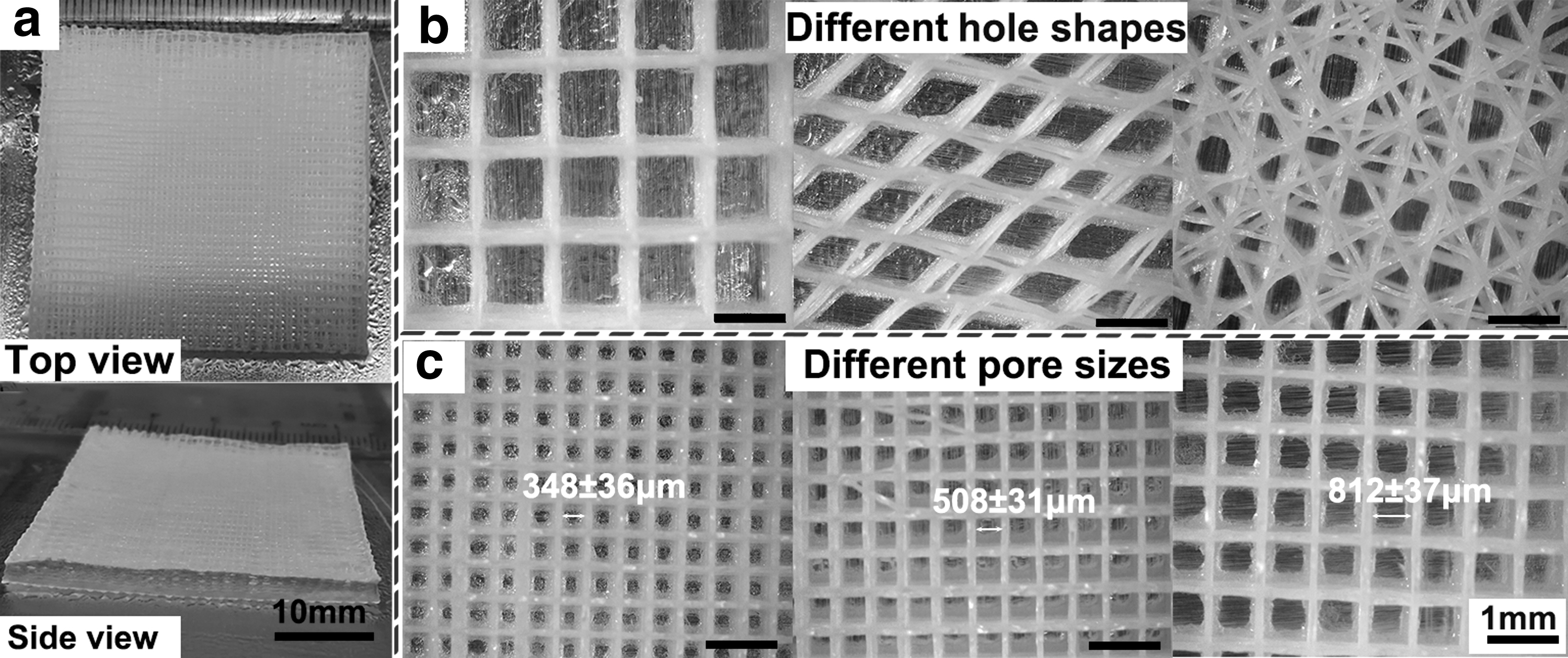
To further demonstrate the feasibility and flexibility of the CEJP process, different scaffolds were printed under the freezing condition. Figure 3a illustrates an orthogonal network scaffold with dimension of 40 × 40 mm2 and filament offset of 600 μm. It took about 80 min to complete the printing of the 50-layer scaffold, and further time was needed with reduced filament offset. From the front view, the appearance of the printed scaffold was square, and the length and width exactly matched the design. Meanwhile, as can be seen from the side view, the height of the side wall was relatively uniform in the center part of the scaffold, but it looked uneven in the corner part. This may be due to the reduced velocity of the collector causing the polymer jet to deform at the turning points or corners. 29 Moreover, the average height of the scaffold was 4 mm, higher than the height of scaffolds printed in the current solution-based electrohydrodynamic jetting printing studies, and most of them were <1 mm. 30 There may be related to the process parameters. To prevent the polymer from clogging the needle at low temperatures, the TCD was higher than that of the conventional EJP process, which allowed more layers to be deposited. Furthermore, the relative high feed rate is another parameter that ensured the continuity of printing process but resulted in slightly large fiber diameter. Thus, the synergistic effect of the two factors made the thickness of the CEJP-printed scaffolds larger than that of the conventional EJP.
Macromorphology of CEJP scaffolds:
In addition to the scaffold appearance, controllable morphology of the internal pores was also a key point reflecting the performance of the printing process. As shown in Figure 3b and c, scaffolds with different hole shapes and pore sizes were printed. The macrographs showed that the orthogonal and diamond-shaped pores can be well printed with regular hole shape, whereas the orthogonal and oblique cross scaffolds experienced some defects at certain part of the filaments. At the same time, images of orthogonal grids showed that the CEJP system can be well adapted to print different apertures, and the minimum pore size in the demonstration was about 350 μm at the filament offset of 400 μm. If the offset was further reduced, the jet will print along the adjacent filament paths, resulting in defects in the scaffold. Although the CEJP process had some flaws, it can still be considered to have good feasibility and flexibility.
Micromorphology analysis of CEJP scaffolds
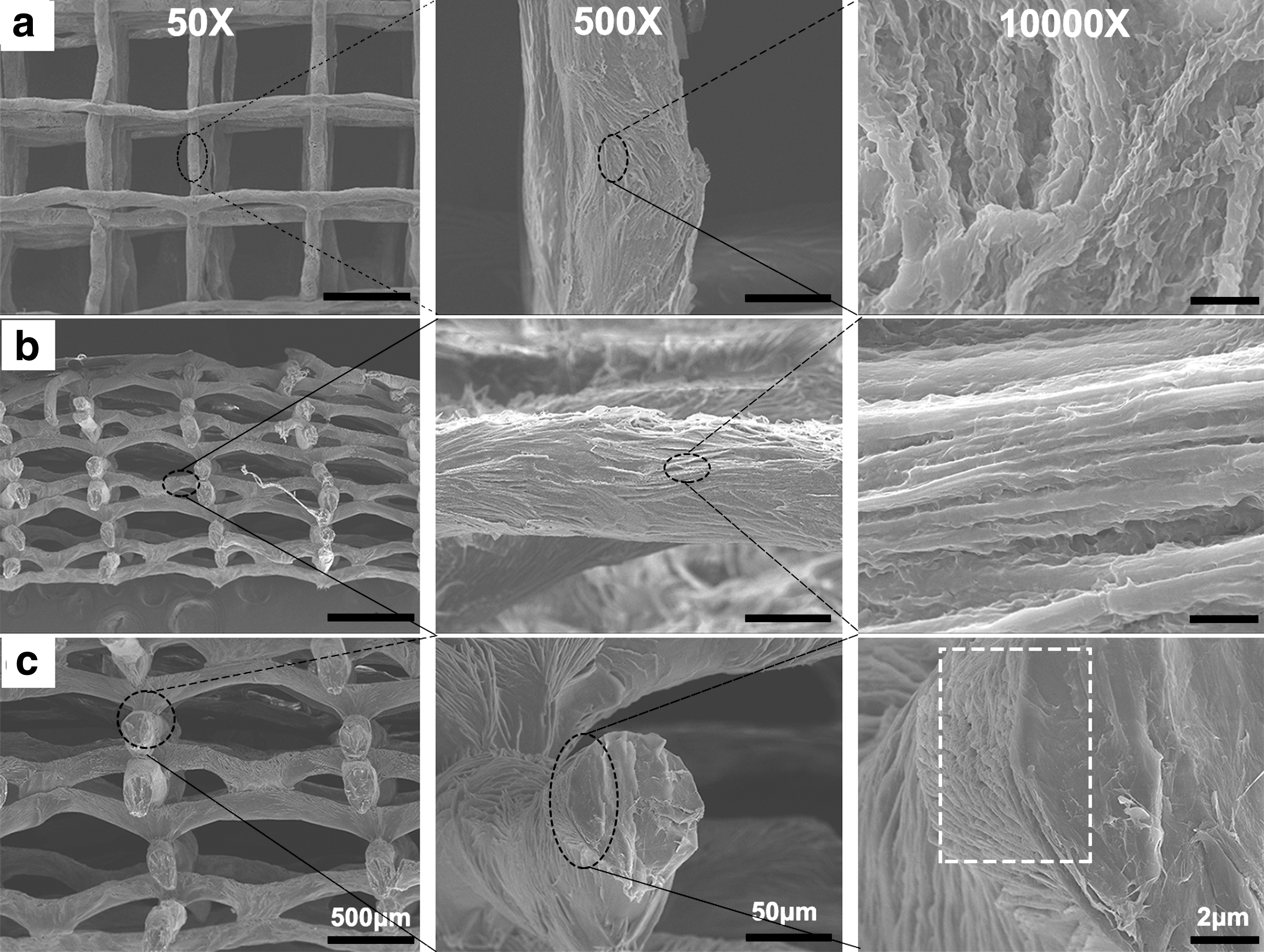
After lyophilization, an orthogonal network scaffold with a 600 μm filament offset was selected for FESEM micromorphological analysis. From the front view, as shown in Figure 4a, it can be seen that the orthogonal networks were constructed by intersecting filaments layer by layer, and their diameters were in the range of 50–80 μm, which was difficult to achieve by extrusion-based 3D printing method. 21 However, the filaments of the dry scaffold were not perfectly straight, which may be due to stress deformation during the lyophilization process. When zooming in one of the filaments, it can be seen that surface of the filament was not smooth, but a specific pattern surface composed of small oriented “ridges” and “valleys.” After further magnification, more ultra-structures were found on surface of the filament. It can be seen that a number of nanoscale or submicron scale bumps and stripes were distributed on the “ridges” and “valleys,” which contributed larger surface area to the scaffold. 20
Micromorphology of CEJP scaffolds with different magnifications:
From the side view, as shown in Figure 4b, except for the design intersection and some defect areas, the upper and lower filaments were separated, which also manifested that PCL polymer jet can freeze quickly during CEJP printing to ensure the formation of 3D structures. The defects may be due to the slower solidification rate at the center part of the suspended filament, causing the upper layer to flow down to the previous layer. More steps were needed to optimize the process window to avoid defects.
At the same time, similar surface patterns of “ridges” and “valleys” were also found on internal filaments, which meant that the entire scaffold was made up of filaments with this specific surface topography. More evidence can be found from cross-section analysis, as shown in Figure 4c, the specific surface pattern appeared only on the shallow surface of the filament (yellow mark), and the feature was not seen inside. The inside of the filaments looked more like a solid structure.
Therefore, from the analysis of process performance and morphology, it can be concluded that CEJP was a suitable system to print fine scaffolds with extra surface morphology. Currently, the system can reach the printing resolution and scaffold thickness of 50–80 μm and 4 mm, respectively. Especially, the filament surface of the printing scaffold consisted of oriented and rough “ridge” and “valley.”
Cell response to the CEJP scaffold
CEJP scaffolds with pore size of 350 μm were chosen for evaluation on cellular response, and BMSCs were cultured on scaffolds for 3 days, then strained and checked with fluorescence microscope. As shown in Figure 5, living cells, dead cells, and the filaments are displayed in green, red, and dark color, respectively. Focusing on top layer first, it can be seen that green colors were scattered on surface of the filaments, and almost all the cells were living. Cells tent to aggregate on filaments, and some of them showed linear shape, which may be caused by the contact guidance of the topography of the filament surface.31,32 Cells and cell clusters can also be seen on the inner filaments, and some green clusters showed obvious orientation, which meant that CEJP scaffolds had the potential to align cells during the culture period.
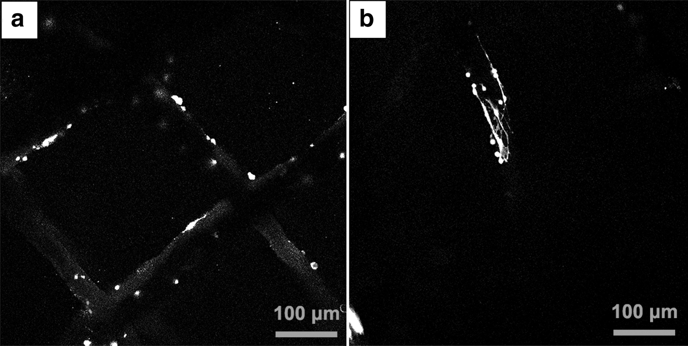
Confocal fluorescent images of scaffolds with adhesive cells:
Conclusions
In this study, a novel CEJP technology was developed by ingeniously combining solution-based EJP with a cryogenic workbench. The freezing temperature of −20°C, created by the cryopump, solidified the jets of PCL quickly and stacked them into a 3D structure, which can be an alternative approach to the solvent evaporation method. Under selected processing conditions, scaffolds with different hole shapes and pore sizes were successfully printed by the CEJP system. The resulting scaffolds, with feature size of 50–80 μm, can reach the thickness of 4 mm, which was larger than that printed by the conventional solution-based EJP method. Another advantage of this method was that it produced specific oriented “ridges” and “valleys” on surface of the filaments, which was beneficial to cell orientation according to the results of cell culture. Although it was difficult to reduce the minimum pore size below 350 μm currently, CEJP can still be considered as a suitable method to print fine scaffolds with extra surface topography for medical applications.
Footnotes
Acknowledgments
The authors acknowledged the State Key Laboratory of Materials Processing and Die & Mould Technology of the Huazhong University of Science and Technology for providing different equipment in characterizations.
Author Disclosure Statement
No competing financial interests exist.
Funding Information
This work was financially supported by the National Science Foundation of China (81672158).
References
Supplementary Material
Please find the following supplemental material available below.
For Open Access articles published under a Creative Commons License, all supplemental material carries the same license as the article it is associated with.
For non-Open Access articles published, all supplemental material carries a non-exclusive license, and permission requests for re-use of supplemental material or any part of supplemental material shall be sent directly to the copyright owner as specified in the copyright notice associated with the article.