
Abstract
Digital light processing (DLP)-based printing process has been used to print microfeature-sized constructs and architectures for biomedical applications; the key challenge is to achieve both large printing size and high accuracy at the same time. Here we reported a scalable DLP-based three-dimensional (3D) printing system with scalable resolution and building size, which was used for printing of multiscale hydrogel fractal bionic channels. Scalable printing was achieved by moving the convex lens of the printing system, and thus, each single micromirror of the digital micromirror device chip corresponded to the single-pixel size scaling from 6 to12 μm. Using this system, we were able to use poly (ethylene glycol) diacrylate to fabricate a variety of multiscale architectures, such as regular fractal Y-shaped channels, and more irregular and intricate geometries, such as biomimetic capillary vascular networks. Blue and red food dye solutions were able to freely fill all these channels in the scaffolds, from the trunk (>1500 μm in width) to small branch (∼30 μm in width) by capillarity. Cell experiments were carried out to certify the biocompatibility of printed multiscale biomimetic channel networks. This work reveals significant progress in printing multiscale constructs with both large printing size and high precision in scalable DLP-based 3D printing.

Introduction
Three-dimensional (3
In the area of DLP-based 3D printing, many efforts have been proposed for improving the performances of the printing system such as printing efficiency, formulation precision, and building size. For improving the printing efficiency, Tumbleston et al. 24 used the continuous liquid interface production method by using the oxygen-permeable window to realize the persistent liquid surface, and this method could greatly reduce printing time. Aiming to improve the formulation precision, Kowsari et al. 10 proposed an optimized way to improve the surface roughness and layering artifacts on the basis of guaranteeing maximum lateral resolution. They studied the fabrication performance of multiple (meth)acrylate-based photopolymers and focused on formulation results varying from single-pixel feature, single-pixel wide line, and multipixel surface, which guided 3D printing fabrication. Xue et al. 25 put forward a multistep exposure method that utilized gradient exposure mask to improve the printed surface's flatness. To compensate undercured regions, additional ultraviolet (UV) exposure was carried out with a study on the relationship between the UV light density, exposure time, and building size. In addition, researchers have carried out researches on enlarging building size, such as Emami et al. 26 proposed a dynamic scanning-projection method for printing of a large part, which combined digital micromirror device (DMD) chip and a moving step to combine projection and scanning. By this method, building size can be enlarged by scanning with the continuously updated projected pattern along with scanning movements. In summary, although recent researchers have carried out studies on promoting the formulation efficiency, improving building precision, and enlarging building size, it remains a challenge to realize an enlarged printing size with high precision simultaneously.
For the fabrication of microfluidic devices for organ-on-chip and tissue engineering research, researchers have focused on DLP-based complex fluidic channel fabrication. Zhang et al. 27 uses the dynamic optical projection stereolithography to fabricate a biomimetic vascular structure. Grigoryan et al. 28 used a customer-designed DLP-based printing system to fabricate multiscale vascular networks and functional 3D intravascular topologies with biocompatible hydrogels. They have made huge progress in artificial intravascular 3D fluid mixers and functional bicuspid valves. For improving the formulation precision of the fluidic channels, Gong et al. 29 proposed a new mathematical model for characterizing the resin optical penetration depth based on the absorber's molar absorptivity. They constructed 18 × 20 μm microfluidic channels with a length of 41 mm. Regardless of whether the existing printing fluid channel is bionic, the researchers only focus on the accuracy of the micro scale or the formation of the macro scale. Little work was proposed on combining macro- and microscale channel forming; here we proposed a scalable DLP-based 3D printing in multiscale bionic-channel fabrication.
In this work, we developed a scalable DLP-based 3D printing system and printing method for the printing of multiscale channels, including multiscale and high-resolution gradient fractal Y channels and bionic multiscale channel network constructs. First, a scalable DLP-based 3D printing system was set up. Parameters such as projection ratio and its corresponding positions of convex lenses and focal planes were experimentally examined. The printing area of scalable printing system ranged from 11.4 × 7.2 mm2 to 22.7 × 14.4 mm2, while the printing resolution in X-Y plate varied from 6.0 to 12.0 μm. Then, the digital masks at different projection ratios were designed to reach the goal of the combination of large building size and high resolution. Fractal Y-like channels were printed using the developed scalable printing method. This is followed by the printing of biomimetic capillary microfluidic channels whose widest part reached 1500 μm, while the thinnest branch was around 30 μm, where blue and red food dye solutions could fill out the bionic to demonstrate its transport abilities. In addition, the cell culturing experiments were performed to study the biocompatibility and functions of the printed biomimetic multiscale channel. The results suggested that cells grew well on our printed channels and had relatively high viability as well as great proliferation. This work reveals significant progress in hierarchically printing of multiscale architectures, which addresses the current challenge in achieving both high resolution and large building size at the same time and provides a potential approach to fabricate a biomimetic multiscale channel for vascular or neural tissue regeneration or any other potential applications.
Materials and Methods
Scalable DLP-based 3D printing system
The adjustable scalable DLP-based 3D printing system mainly consists of four submodules: a projection module, a projection scale change module, three-axis linear stage, and an optical observation module with a 10 times industrial camera, as shown in Figure 1. The projection module was a refitted high-resolution DLP-based projector (H6521BD; Acer), containing a diagonal length 0.48-inch DMD (Texas Instrument, Dallas, TX) with 1920 × 1200 micromirror array. To fulfill the requirements of designed system, a series of lens of projector were removed. The modified projector was connected to a PC computer through an HDMI connector, and the computer can send the designed masks with programmed time to generate the reflective micromirror array into the corresponding pattern and then projected upward through the glass plate. The optical source in the refitted projector was a high-pressure mercury lamp whose wavelength was 200–2000 nm for a wide selection of photosensitive resins and photoinitiators.
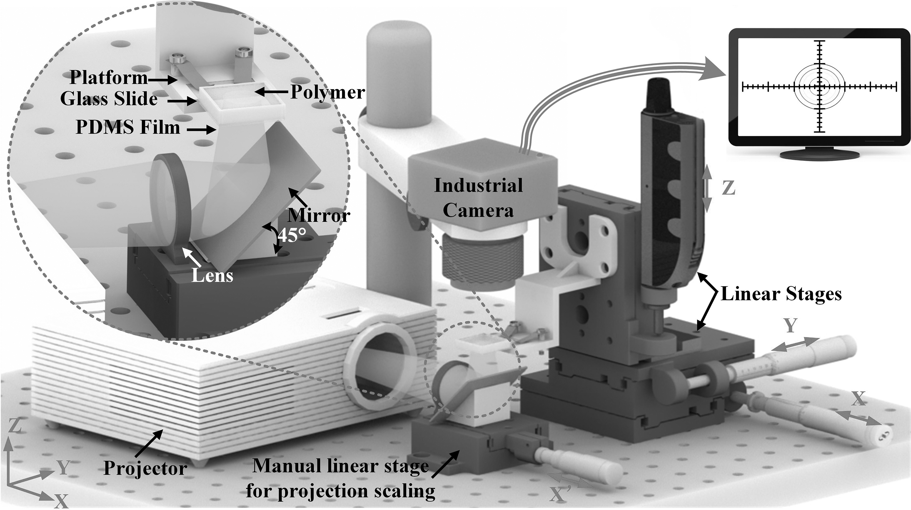
Schematic view of the scalable-based three-dimensional printing system.
The projection scale change module was combined with lens together with an aluminized mirror fixed on a manual linear translation stage in X′-axis, as shown in Figure 1. The patterned light from the projector passed through the convex lens and then reflected when it met the reflective mirror, and finally projected vertically upon the glass slide, as illustrated in Figure 1. After patterned light enlarged or reduced by the projection scale change module, it reached a focal plane and solidified patterned hydrogel. With the movement of X′-axis manual linear stage of the projection ratio change module, the distance between the lens system and the DMD chip was changed. Thus, the pixel size at image plane can be continuously changed from 6.0 to 12.0 μm, and the diagonal length of the projection area was varying between 13.5 and 182.9 mm, while the projection area changed from 11.4 × 7.2 mm2 to 22.7 × 14.4 mm2.
Three-axis linear moving module has two manual linear stages (SM-50; Newport, Irvine, CA) in X-Y plane and a motorized Z-axis actuator (LTA-HS; Newport) with a minimal increment motion of 0.10 μm. A glass slide was loaded on the 3D-printed low-viscosity resin (Somos® GP Plus 14122, Shanghai, China) platform. A 500-μm-thick polydimethylsiloxane (PDMS) film stuck around the glass slide and a cover glass was put onto the thin film. During the printing process, the photopolymer and photoinitiator mixture was added into the 500-μm-thick liquid tank. The patterned light was projected upward to the bottom of the glass slide and the photopolymer was cured.
Working principle of scalable DLP-based printing method
Because the printing precision was mainly determined by the width of the single pixel projected upon the liquid tank, this was determined by the width of single micromirror multiplied by projection ratio. The building size, also known as projection size, was decided by projection area onto a liquid tank, and equal to the effective DMD chip area multiplied by projection ratio. Therefore, the projection ratio was equal to the projection size at the printing platform divided by the DMD chip size. According to the principle of lens imaging, the projection width could be changed continuously by adjusting the distance between the DMD chip and convex lens, as well as the distance of convex lens and printing platform, as shown in Figure 2. For instance, at an enlarged projection ratio, the extended projection size and lower precision were acquired, while at a reduced projection ratio, higher precision, but contractible projection size, was achieved. So as for high-resolution printing, the projection size had to be reduced. Conversely, for large projection size, the printing precision would be enlarged with the increasing of projection ratio.
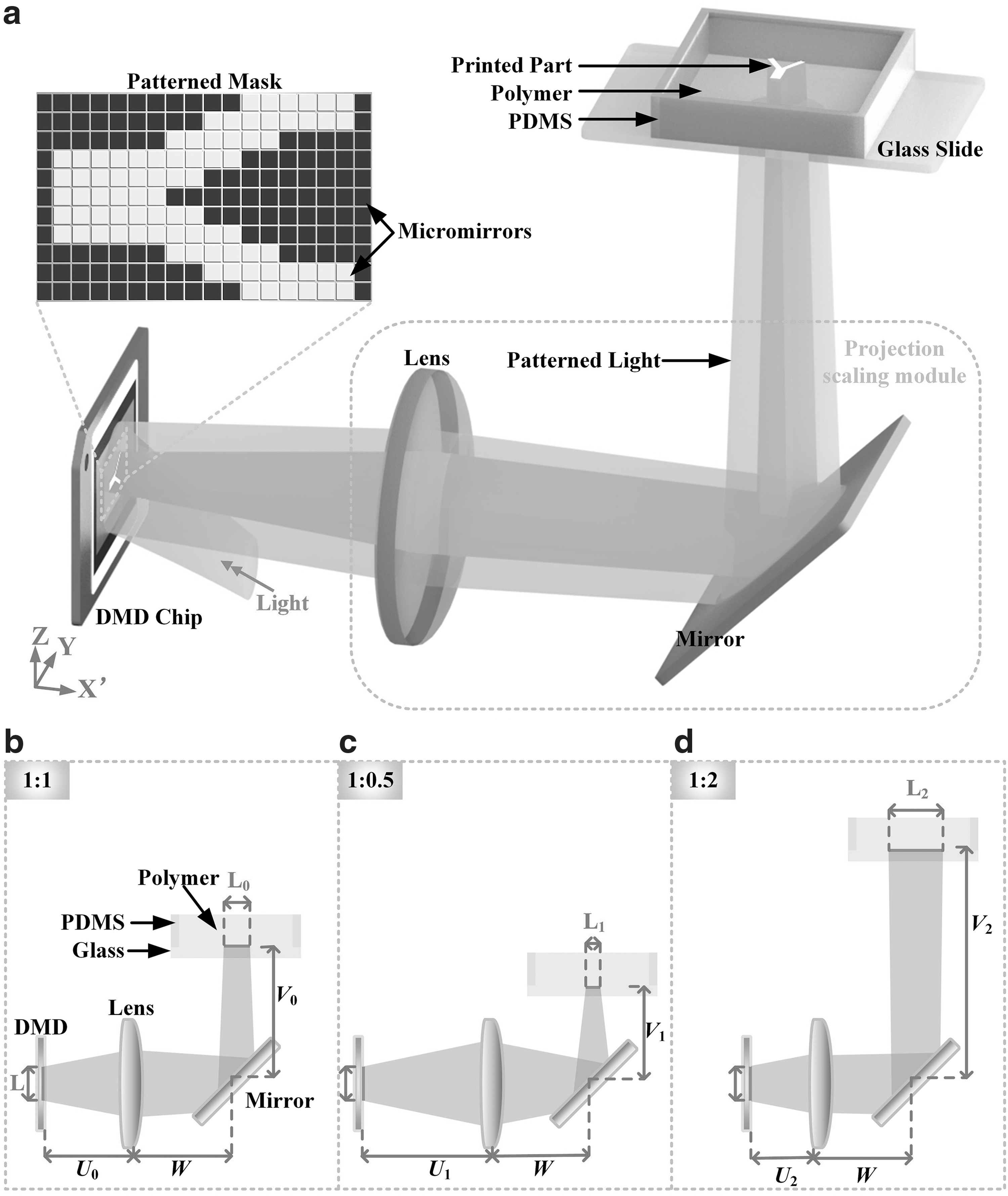
According to the law of convex lens, we changed the distance (U) between the DMD chip lens systems. The distance between lens and mirror is set as W, and the distance between the mirror and glass slide was V. Typically, W = J + V, where J was fixed in this printing system. When the object was located at twice the focal length of the object lens, an inverted real image of the same size of L has formed on the image side and double focal length, as shown in Figure 2b. When the object was located outside the focal length of the object lens, a reduced inverted real image of 0.5 L was formed outside the focus of the image and within the focal length of the image, as shown in Figure 2c. As the object is within the focal length of the object lens, outside the focus, an enlarged inverted real image of 2 L was formed outside the image twice the focal length, as shown in Figure 2d. Thus, U1 > U0 > U2, and V1 <V0 <V2 can be observed in Figure 2b–d.
In this study, the throw ratio of the DMD chip width to projection width was continuously changed from 1:1.1 to 1:2.2. As the original width of a micromirror of DMD chip is 5.4 μm, at the printing scale ratio of 1:1.1, the projection width of a single pixel was about 6.0 μm, the diagonal length was 13.5 mm, and the whole projection area at printing platform was 11.4 × 7.2 mm2. At the printing scale ratio of 1:2.2, the corresponding projection width of the single pixel was 12.0 μm and the whole projection area at forming glass was about 22.7 × 14.4 mm2.
Structure of microfluidic channels
To study the capability of the developed scalable DLP-based printing system, we proposed a Y-shaped symmetrical fractal channel with the fractal order of 7, where for each Y channel, the width of the main channel was twice larger than that of the sub-branch channel, as shown in Figure 3a-i. The branch angle was 120°. The thinnest branch was only 8 pixels at a ratio of 1:1.1, in other words, the projection width was about 48 μm, as shown in Figure 3a-iv. At the projection ratio of 1:2.2, the widest channel can reach up to 2880 μm. The widest part was 60 times wider than the thinnest part.

Furthermore, to mimic the networks in a human body such as blood vessels, neural networks, and the endotracheal tubes in the lung, we designed a bionic multiscale channel network, as shown in Figure 3b-i. Based on the structure of native vascular networks, we designed a bionic multiscale vascular network pattern according to our previous method. 16 The thinnest part was about 30 μm, which was similar to the size of capillary in the human body. The networks play a role as a transporter. This bionic fluidic channel network has the bilateral gradient, and abundant branches were designed in the center of the joint network tunnels where the width was 30 to 50 μm. The designed biomimetic channel network has multiscale channels, of which the thinnest part was only 30 μm, while the span cross was about 18 mm. Thus, the designed vascular-like channel network has a millimeter-scale span cross and a micrometer-scale channel. The largest tunnel width was designed at a large-scale ratio of 1:2.2, where the design pixel was 130 pixels and projection width was 15.6 mm. The thinnest part was designed at a small ratio of 1:1.1, where the designed width of a pixel was 5-pixel and projection width was about 30 μm, as demonstrated in Figure 3b-iv. As for the designed channel patterns (Fig. 3a-ii, b-ii), the mask pattern at a smaller projection ratio will be projected onto a larger mask pattern to increase the printing precision.
The scalable printing method of the multiscale channel network in our developed printing system can be described, divided into three steps. First, the pattern was divided into two parts for separate print: a detailed one and a large span cross one, as shown in Figure 3a-ii and a-v. Second, the detailed part needs to be enlarged twice of its former size and projected at half the ratio, while the large span cross one would keep its original size and project at the normal ratio. This step can help the microscale structure maintain its detailed structures. By comparing Figure 3a-iv and (a-vii), it is obvious that the former one kept the details of the same oblique line better. Third, the pattern Figure 3a-iii was printed at the ratio of 1:1.1, and the system was moved to the position where the projection ratio was 1:2.2. The alignment work was proposed with the assistance of cross-markers. After that, the pattern Figure 3a-vi was printed at a ratio of 1:2.2. By using the above three steps, the whole multiscale channel network was successfully printed.
Material preparation and printing procedure
Acrylate-based photopolymers have been used widely in the DLP-based 3D printing system. The poly (ethylene glycol) diacrylate (PEGDA) was selected due to its biocompatibility and low cost. The prepolymer light-sensitive mixture solution was prepared based on the PEGDA (average Mn 700; SIGMA-ALDRICH, St. Louis, MO), and 1% (wt/vol) ethyl (2,4,6-trimethylbenzoyl) phenylphosphinate (TPO-L; ALADDIN, Shanghai, China). The absorption peaks of TPO-L were 299 and 366 nm. Then, the solution was put into a brown bottle and mixed evenly by using the ultrasonic dispersion for 15 min. The solidification principle is described in Figure 4. As shown in Figure 4a, when the initiator is exposed upon the absorption of UV-light, a specific bond within the initiator's structure undergoes hemolytic cleavage to produce free radicals. After that, as shown in Figure 4b, the polymerization of two or more monomer units will induce macromolecular monomer polymerization, and generate the polymer network structure. By removing the liquid part and drying the printed model, the patterned structure will be printed, as shown in Figure 4c.

Chemical structure of PEGDA, which was bonded with free radicals of light initiator connect with carbon/carbon double bond, and then there produced a network structure of PEGDA polymers. PEGDA, polyethylene glycol diacrylate.
After preparation of the printing material, it was used to print the designed Y-shaped symmetrical fractal channels and bionic capillarity multiscale channel networks. A two-step printing procedure is utilized: step 1, the small mask patterns (Fig. 3a-iii, b-iii) were sent to the DMD chip through a computer. Then, the manual linear stages were moved to the position where the small pattern masks were shown on focus upon glass slide at the projection ratio of 1:1.1. Typically, the positions of the X′-axis and Z-axis were at 13.00 and 46.55 mm, respectively. After that, the patterned light was passed through the convex mirrors and reflector and projected upward to the glass slide, which leads to the solidification of photopolymer mixture. The exposure time was set as 0.5 s. Step 2, the above printed channels at 1:1.1 ratio were first observed under the industrial camera with a 10 × optical eyepiece. After alignment, the manual linear stages of X′- and Z-axes were moved to the position where the projection ratio was 1:2.2 and single-pixel width was 12 μm. The mask patterns shown in Figure 3a-iii and b-iii were uploaded and printed at a projection ratio of 1:2.2, with an exposure time of 1.5 s. Then, the whole fluidic channels at two different projection ratios were printed. To examine the printing accuracy of the constructs, a laser confocal microscope (LEXT OLS4500; Olympus, Tokyo, Japan) was used to obtain the 3D structures of the hydrogel channels.
Cell culturing and seeding
The printed bionic multiscale channel network can be used for cell culturing and seeding. To establish a neuronal network, the PC12 cells were chosen as suitable cells for the study of the biomedical and functional properties of neuronal cells in vitro. Here, the PC12 cells were adapted to test whether the cells can grow in the printed bionic multiscale channel network.
PC12 cells (obtained from Cell Bank of the Chinese Academy of Science, Shanghai, China) were cultured in Dulbecco's modified Eagle's medium (Hyclone, supplemented with 10% fetal bovine serum [Gibco]) in an incubator at 37°C, 5% CO2 (Thermo Scientific, Waltham, MA). For cell culturing, the PC12 cells were first digested by 0.125% tryspin-ethylenediaminetetraacetic acid (EDTA) and centrifuged for 1 min when seeding the cells, and a cell suspension at a density of 1 × 10⁶ cell/mL was prepared for perfusing and seeding. Then, the cells were carried out using a pipette to transfer the PC12 cell suspension on the channel network's inlet, and to let the cell suspension flow into the channel without pump until the whole channel network was immersed.
The viability and proliferation of PC12 cells dispersed in the microchannel were evaluated based on fluorescent observation using a LIVE/DEAD™ Viability/Cytotoxicity Kit at 12, 24, 36, and 48 h, and the cell morphology is obtained by observing the results of the microscope (Ti-S; Nikon, Tokyo, Japan).
Results and Discussion
Printing results of the multiscale channel network
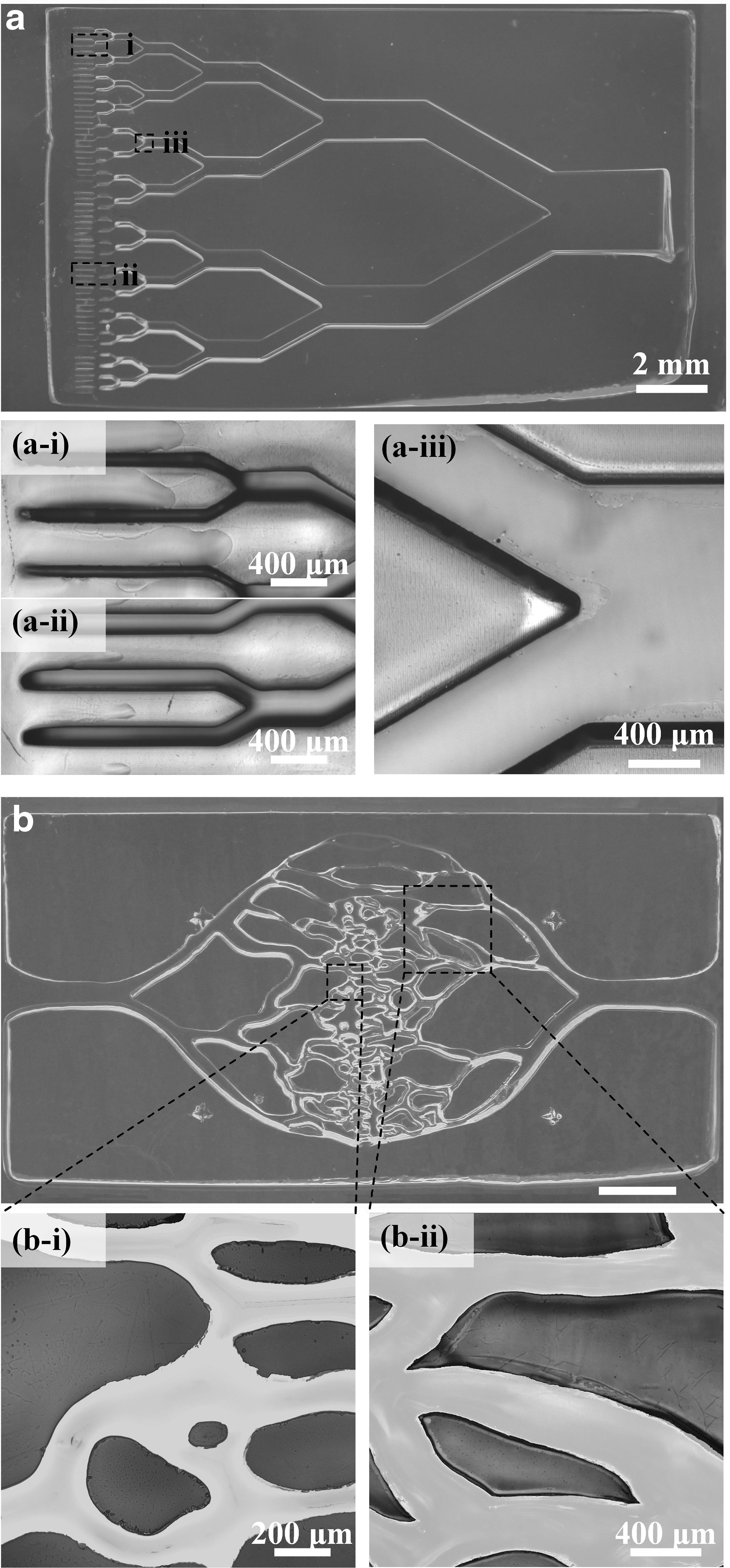
To study the capability of the scalable projection method for multiscale channel network printing, both the original and scalable DLP-based printing methods are utilized. At different projection ratios, the exposure time needs to be carefully selected. Here, to print the multiscale channels with a height of 500 μm, the exposure time for the projection ratio of 1:1.1 is set as 0.4 s, while the exposure time is set as 1.5 s for the projection ratio of 1:2.2. The scalable DLP-based printing results of the Y-shaped fractal channel and bionic multiscale channel networks are shown in Figure 5. The printed hydrogel channels were observed using a laser scanning microscope. We can see that the printed Y-shaped channels have the fractal order of seven, as in Figure 5a. We measured the width of each order of channels and compared with the designed values; the mean value and its deviation value are calculated and listed in Table 1. The percentage of the discrepancy between the measured average and designed value is calculated.
The Width of the Printed Multiscale Channels
We can see that both the printing methods had a relatively good performance for the printing of multiscale fractal channels with the fractal order <5, as shown in Figure 5a. The discrepancies between the printed and measured width of each channel are all <3%. With the increase of fractal order, the discrepancies between the measured and designed channel width are generally increased. Scalable printing showed its advantages in the printing of multiscale channels with both large scale and high accuracy, as shown in Figure 5a-i and a-ii. For example, for the channels with fractal order of 6, the scalable printed channel has a lower width discrepancy of about 8.85% than that of regular DLP-based printing (∼12.10%), as shown in Table 1. Especially for the thin channels with fractal order of 7, the printed channel branch was blocked when using regular printing method. By contrast, using scalable printing, the thinnest channel can be successfully printed with a width of about 56.49 μm. The multiscale channel network was fabricated separately by three parts: enlarged projection part at the 1:2.2, the reduced projection part at the 1:1.1, and the joint part that was the border of the former projection parts.
For scalable printed Y-shaped fractal channels, at a projection ratio of 1:2.2, the actual printed channel width is more accurate than that under the projection ratio of 1:1.1. As the increased fractal order and narrowing of the channels, the white pixel numbers grew, while black pixel numbers reduced. Considering the bending light from air to photopolymer, the actual projection area was usually smaller than the designed area. Together with the overcured larger white part,21,28 the discrepancies between the measured and designed channel widths become greater, and the maximum discrepancies can reach up to 25.53%. The sights of the printed fractal channels at orders of 6 and 7 under a laser scanning microscope of 5 × and 10 × objectives are illustrated in Figure 5a-i and a-ii.
Fluid perfusion of bionic multiscale channel networks
To demonstrate the abilities of the printed bionic channel network for application in cell seeding and microfluidics, fluid perfusion experiments were performed. Unlike other active perfusions, which require a syringe or pump, the bionic channel shown here was perfused through passive capillary action alone, as shown in Figure 6. Capillary motion is the ability that liquid can be propelled with the combination of surface tension and adhesive forces between the liquid and container wall. This pumpless method helps to show the perforation of fabricated channel networks. 30 Each channel was fully perfused when dye solutions were dropped at the inlet and outlet. At t = 0, 4, and 10 s, the dye solution perfusion results of the bionic channel network are shown in Figure 6a–c, respectively. After 4 s, the dye solution filled about half of the fluid area. After 10 s, the red and blue dye solutions filled the whole channel and the mixture purple part occurred.
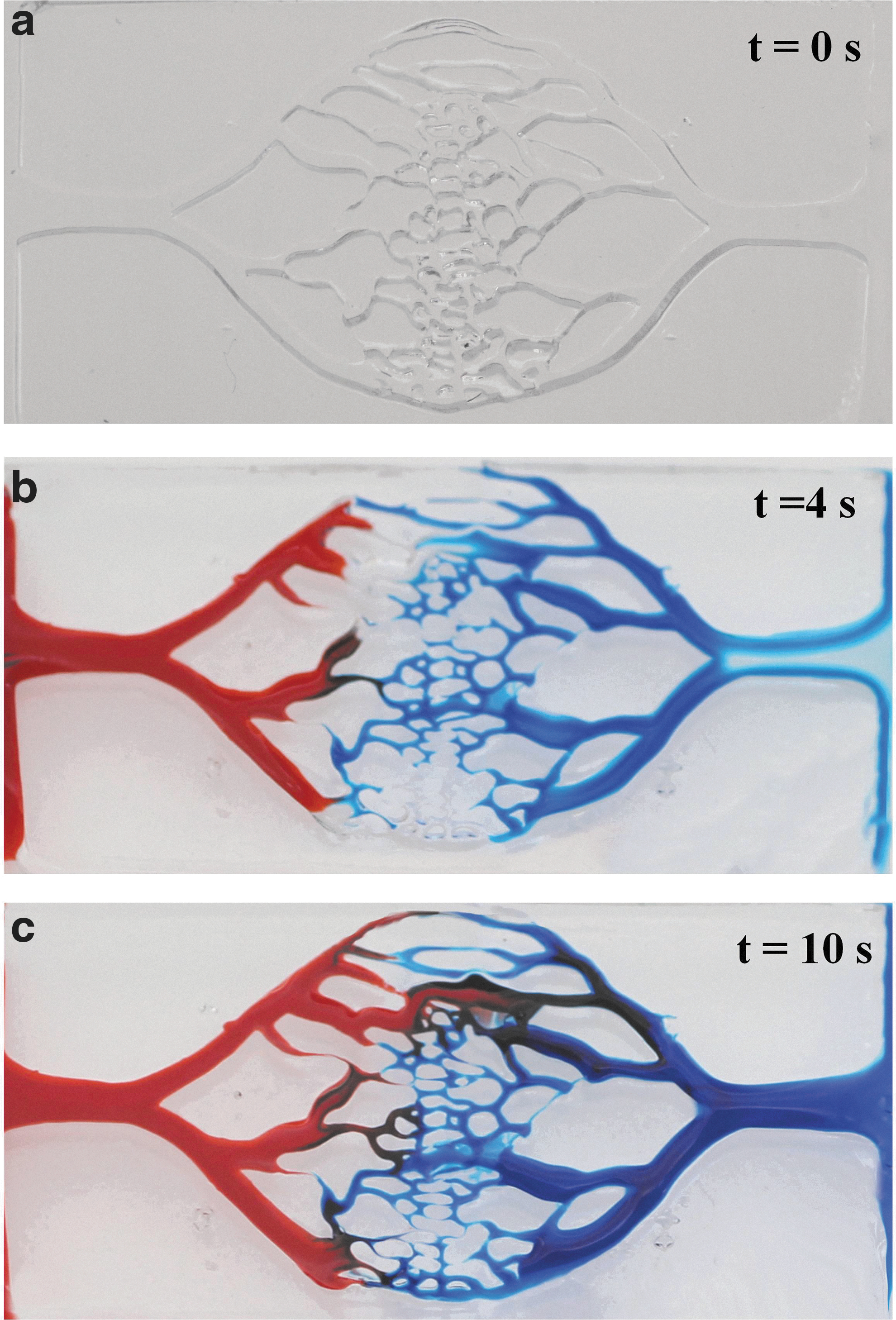
Sequential images of perfusions show the fluid flows through the entire bionic multiscale channel network.
Cell proliferation and morphology in bionic channel network
To verify the biocompatibility and capability of the bionic channel network for cell culturing, PC12 cells were seeded on the bionic channel network we built. As shown in Figure 7 a and b, the fluorescent micrographs of cell attachment to the bionic channels after 12 and 48 h showed that the cells can grow on the printed multiscale channels at the same view. If we take the same view of bionic channel networks, the growth of cell density can be observed. The synapsis of PC12 cells grew as a symbol that the cell activity gradually became better with increased time. Since PC12 cells are nerve cells that need to have a partial function, the spreading of cells indicates that they attached well on the surface of multiscale channel networks. Besides, the cell viability was recorded, as shown in Figure 7c. During the 48-h culturing, cell viability was remaining more than 85%, after 48-h culturing, it can reach up to about 90%. Generally, cell proliferation increased gradually, after 48-h culturing, the number of cells reached more than twice than the first 12 h, as shown in Figure 7d. It illustrated that the cell grew and proliferated well in the designed multiscale bionic channel network during the culturing time. The high-precision printed edge, unobstructed, played an important role to reduce the shell force during the flow of liquids. Also, the surface was smooth and clean, which offered a good living environment for cell proliferation.
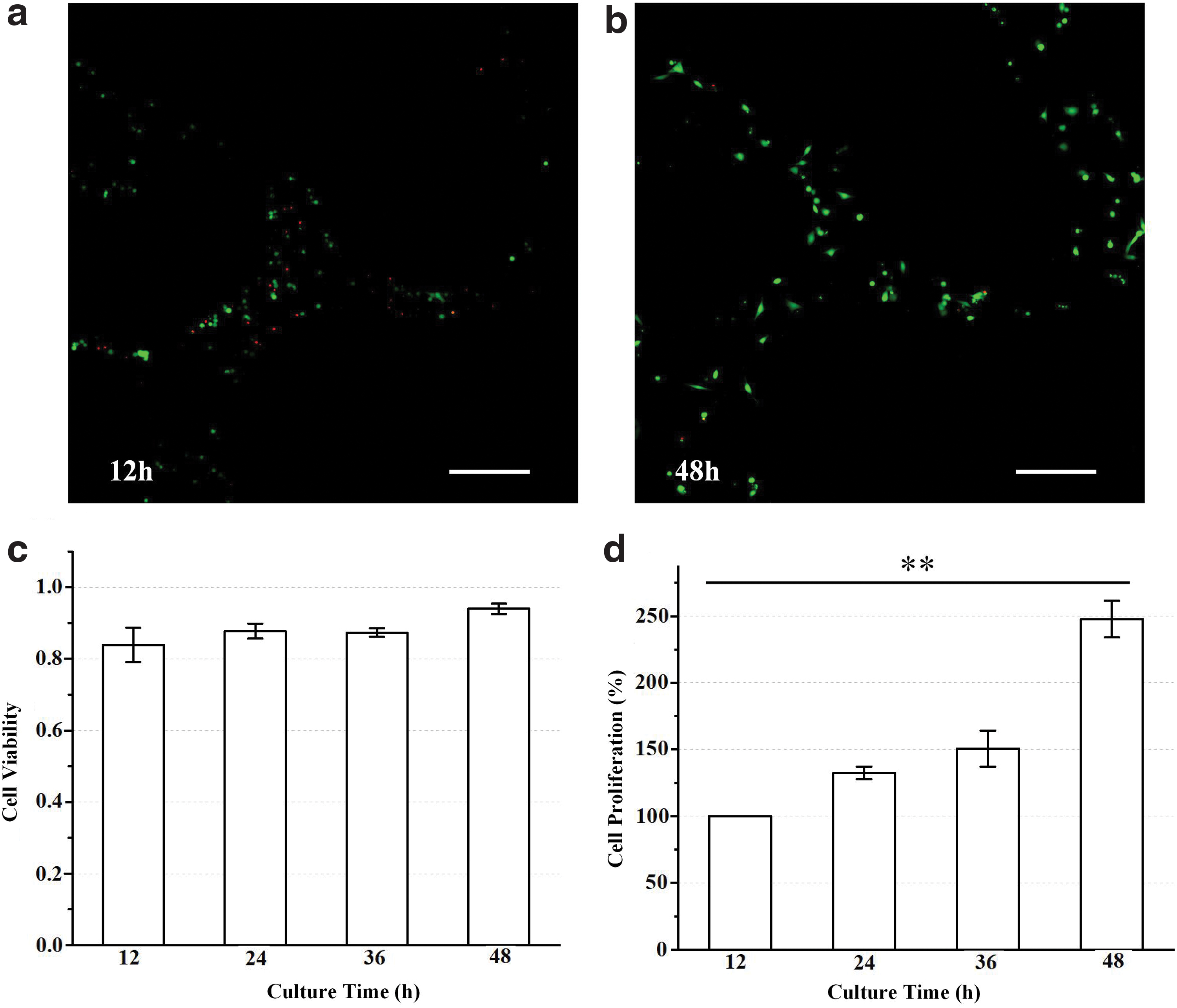
Fluorescent images of cell viability after
It was also observed by the results of cell culturing that the cells spread after 48 h of culturing, as shown in Figure 8. After 48 h of incubation, we selected several channels (Fig. 8a) to observe the formation of tubular channels covered by the cells. As shown in Figure 8b–d, the cells were habitually attached to the inner wall of the channels, and then spread in the middle. If the culture time of the cells is prolonged, a flow path covered by the cells should be formed in the middle of the microchannel. The results have shown that the microchannel built by this work can be used to culture cells and form cell-coated flow channels. The biomimetic channel network provided a guided culturing environment for cell adhesion and proliferation. As shown in Figure 8d, we can see that some of cells became polygonal shaped instead of its regular round and short shape. That demonstrated the cell differentiation occurred, which was a symbol of cell growth well, and adhered to the channel well. 31

Conclusions
In summary, a scalable DLP-based 3D printing method was developed for the fabrication of bionic multiscale fractal channel networks. The major advantages of scalable DLP-based printing enable us to print the complex constructs with both large size and high accuracy. The working principle and system setup for scalable DLP-based printing are described. The Y-shaped fractal channels and bionic capillary channel networks are successfully fabricated by using the scalable DLP-based printing, and results showed that the printed multiscale channel networks have relatively high accuracy. Dye solution perfusion results showed the high connectivity of the printed channel networks. PC12 cells were cultured by inletting the cell suspension solution into the fabricated channel network. Cell viability and proliferation were measured. Cell morphology was observed under a fluorescent microscope. Cell differentiation occurred in some parts of the cells. In future work, we would pay more attention to more complex structures to explore the possibility of a larger building size and a higher manufacturing precision. A high-throughput fabrication research would be carried out. Complex three-dimension microfluidic channel network manufacturing would be discussed for application such as in organ-on-chip and 4D printing. While the exchange of nutrition and waste will be evaluated quantitatively by both stimulation and experiment methods. Fluidic mechanism will be taken into consideration on cell culturing in channels and networks. This work provided a simple but effective approach to fabricate biomimetic channels where the detailed part was 30 μm width, and would further contribute to developing novel heterogeneous structures for tissue engineering and drug delivery.
Footnotes
Author Disclosure Statement
No competing financial interests exist.
Funding Information
This work was supported by the Zhejiang Provincial Funds for Distinguished Young Scientists of China (LR19E050001), Key Research and Development Program of Zhejiang Province (2020C01034), Open Fund Projection of Zhijiang Laboratory (2019MC0AB02), and the Fund for Creative Research Groups of National Natural Science Foundation of China (51821093). The authors appreciate sponsorship from the China Scholarship Council.