
Abstract
Polyphenylene sulfide (PPS) is a high-performance, low-cost special engineering polymer. The mechanical properties of three-dimensionally (3D) printed PPS samples are affected by the mass of the melt extruded filament and the printing pattern in the inner layer. The present study demonstrates the effects of the melt extrusion and filament alignment parameters on tensile, bending, and impact strengths of 3D printed PPS samples. The results indicate that by increasing the melt extrusion parameters, the tensile and bending strengths of 3D printed PPS samples can be improved and internal voids between adjacent filaments can be eliminated. However, the impact strength was restricted by excess melt extrusion. By measuring the strength of 3D printed PPS samples with different filament alignment, we observed that the tensile and bending strengths increase with decreasing angle between the filament and load direction. Moreover, the local tensile strain between adjacent filaments and slippage of the microstructure cell formed by aligning the filament are thought to absorb the impact energy. This study provides a useful guide for selection of appropriate printing parameters to realize a diverse range of mechanical properties for 3D printed PPS samples.
Introduction
Polyphenylene sulfide (PPS) is a semicrystalline thermoplastic material and a high-performance, thermoplastic special engineering polymer that offers a unique combination of properties. 1 The polymer has good thermal stability, high physical strength, and is easily processed. Zhou et al. 2 and Gu et al. 3 found that PPS exhibits high mechanical strength, good dimensional stability, high fatigue resistance, thermal stability, and chemical resistance because of the rigidity and regularity of its molecular chain, comprising an alternate benzene ring and sulfur atoms, and its crystallinity of up to 70%. 4 PPS has been widely applied in the automobile, electronics, and aerospace fields, among others, because of its low cost and excellent properties among special engineering plastics.5,6 However, the application of pure PPS resin has been limited because of its relatively low glass transition temperature, brittleness, and poor impact strength.7–9 To overcome these adverse effects, the common method is compounding with other polymers10,11 or rigid particles,12,13 and this is indeed an effective way to improve the properties of this polymer. Three-dimensional (3D) printing has been increasingly implemented over the past several years as an efficient method to produce objects from a variety of materials and create impossible geometries. Fused deposition modeling (FDM) is the most commonly used method of 3D printing. From the principle of the FDM process, the overall deposition process and FDM pattern can be regulated through change in printing parameters to control the properties of FDM parts. This technology has made it possible to overcome the adverse effects of PPS materials. Geng et al. 14 analyzed the effect of the printing environment temperature and heat treatment conditions on the mechanical strength of FDM PPS samples. The heat conduction of the surface of FDM PPS samples increased when an air-forced cooling method was applied, which was associated with homogeneous crystallinity. When air-forced cooling was used, the heat conduction of the FDM PPS surface increased and the degree of crystallinity was uniform. Fitzharris et al. 15 compared the effects of material properties on the warpage deformation of FDM PPS and polypropylene. The results indicated that the coefficient of thermal expansion mainly determines warpage deformation of FDM samples. Kishore et al. 16 fabricated PPS filled with carbon fiber using the FDM process. The rheological and thermal properties of PPS/CF were measured to determine the printable parameters.
However, it is challenging to print PPS samples with ideal performance and precision because of the complex printing parameters, temperature evolution, and material properties.17,18 Sood et al. 19 analyzed the effect of printing parameters on the compressive strength of FDM acrylonitrile–butadiene–styrene samples using a quadratic response surface model. The FDM process was highly dependent on printing parameters, and the compressive stress was affected by the anisotropic and brittle nature of the printed part. Chacón et al. 20 investigated the effects of the build orientation, layer thickness, and feed rate on tensile and bending strengths of FDM polylactic acid parts. It was concluded that the samples exhibited significant anisotropic behavior in different printing directions. With decreasing layer thickness and increasing printing speed, the ductility of the sample decreased. Mohamed et al. 21 explored the relationship between the printing parameters and wear mechanism of 3D printed samples using definitive screening design methods. Yang et al. 22 found that thermal processing conditions in the FDM process and heat treatment conditions affect the crystallinity and mechanical properties of 3D printed PEEK samples. The variation of the microstructure was shown to be the main reason for different wear behaviors.
The interaction of printing parameters and mechanical properties of 3D printed samples is typically neglected. For example, the effect of filament alignment on the mechanical properties of an FDM sample is suppressed by the increase of the mass flow rate of the extruded polymer. 23 The internal voids between adjacent filaments are eliminated, and the inherent material properties become a crucial factor dominating the mechanical properties of 3D printed parts.24,25 In addition, printing parameters related to filament alignment, such as the infill angle and number of outlines, are also affected by the diameter and quality of the extruded filament and bonding formation of adjacent filaments.
Therefore, the present work focuses on understanding the effect of printing parameters on the mechanical properties of 3D printed PPS samples. These parameters are divided into melt extrusion parameters (extrusion multiplier, raster gap, and outline overlap) and filament alignment parameters (infill angle, number of outlines, and layer thickness). The tensile, bending, and Izod notched impact strengths were measured to provide insight into the complex dependency of the mechanical properties on printing parameters. A single-factor experimental method was used to analyze the effect of filament alignment parameters on the performance of 3D printed PPS samples. Our results indicate that 3D printed PPS parts with a diverse range of mechanical properties can be fabricated by adjusting the printing parameters.
Experiments and Methods
Materials and sample fabrication
PPS is a type of semicrystalline polymer, and the ambient temperature greatly affects its crystallinity. When the PPS melts and is extruded through a heating nozzle, the temperature gradient change results in nonuniform crystallization, which leads to residual thermal stress and warpage deformation. Therefore, in this study, a self-made, air-forced cooling system was placed near the nozzle to accelerate the airflow rate on the surface of the printed sample and reduce the crystallization behavior and residual thermal stress. More details about the self-made, air-forced cooling system are shown in our previous work. 14
Experimental design
As shown in Figure 1, the PPS was heated and melted and then deposited layer by layer according to the printing trajectory. The performance of 3D printed PPS samples is dictated by the mass of melt extrusion and the filament arrangement. These printing parameters are defined as follows:
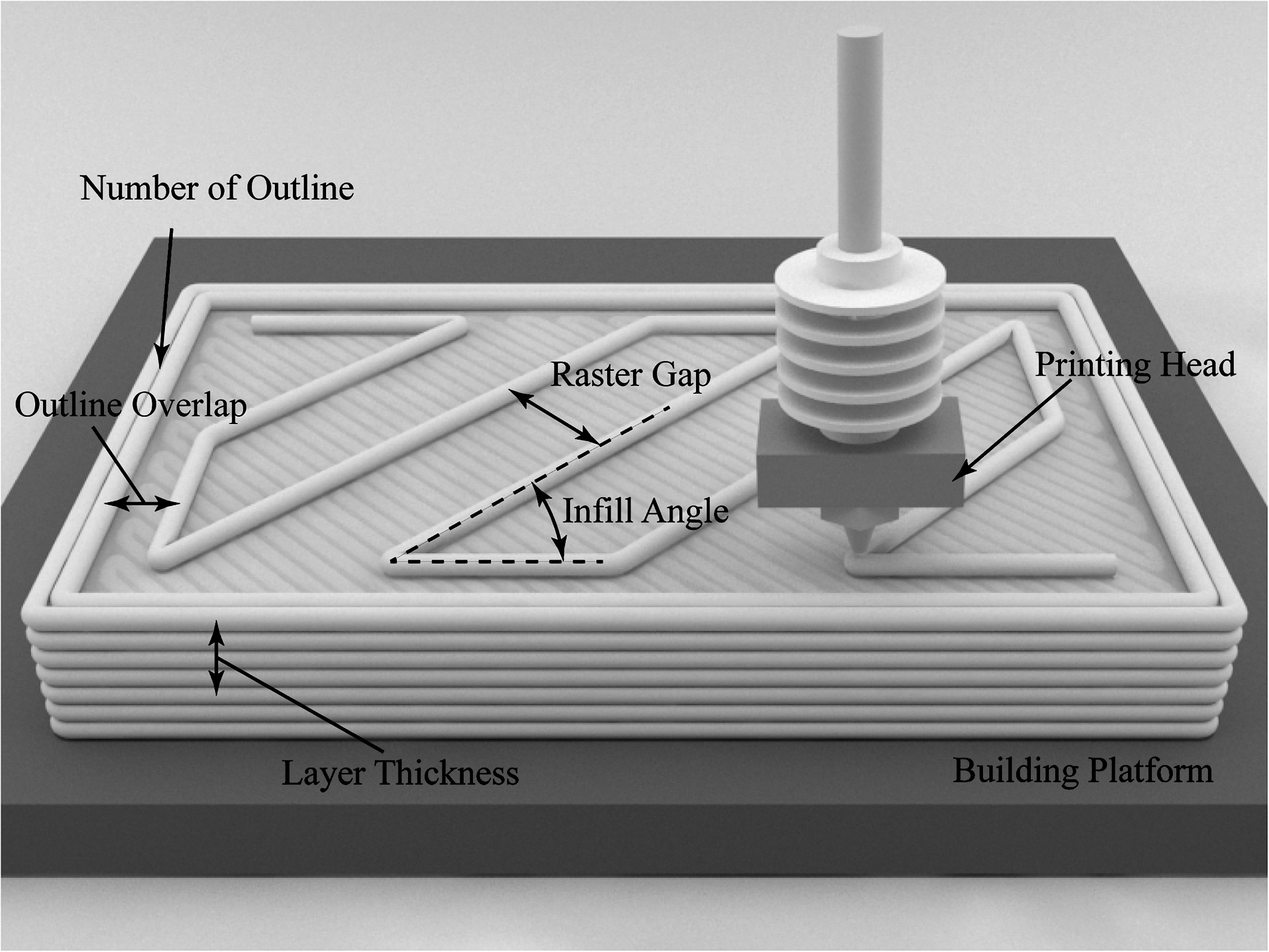
Schematic diagram of a 3D printed PPS sample. 3D, three-dimensional; PPS, polyphenylene sulfide.
(a) Extrusion multiplier: neglecting the extrusion melt compressibility, the volume of PPS pushed into the heat block and the volume of the filament extruded from the nozzle are equal. Therefore, the extrusion multiplier η can be defined as
where V1 is the actual volume of PPS for printing and V0 is the required volume of PPS calculated according to volume conservation.
(b) The raster gap is the spacing between adjacent filaments.
(c) The outline overlap is the overlapping rate between the outline and infill of the printed sample.
(d) The infill angle is the angle between the infill filaments and the longest direction of the sample.
(e) The number of outlines is the number of shells used for the exterior skin of the part.
(f) The layer thickness is the thickness of each printed layer.
Table 1 lists the fixed factors and Table 2 lists the factors and levels of the response surface methodology (RSM) experimental design method. This technique allows reducing the number of runs effectively and explores clear relationships between several parameters at the same time. Chacón et al. 20 as well as others26,27 have successfully applied this method to other similar research on FDM process parameters. These factors have been selected for their high correlation with mechanical properties of 3D printed parts and their levels were determined with a series of preliminary experiments.
Fixed Factors and Their Levels of Fused Deposition Modeling Polyphenylene Sulfide Samples
Response Surface Methodology Experimental Design Method Factors and Their Levels
To obtain reliable experimental results, a six-center design was selected, and the mechanical strength under different parameters was determined from the average value of five samples. Furthermore, effects of the filament alignment parameters (infill angle, number of outlines, and layer thickness) on the mechanical properties were also evaluated. The factors and levels of the experimental design are shown in Table 3. Previous experiments have shown that the effects of filament alignment parameters are suppressed, 28 which are associated with an increase of the mass flow rate of the extruded polymer. From the principle of the FDM process, filament alignment should have a significant effect on mechanical properties, but with the increasing mass of melt extrusion, the excessive melt supply suppressed the significance of filament alignment parameters in response to mechanical properties. Therefore, samples were printed using different filament alignment parameters and an extrusion multiplier of 0.9, raster gap of 0, and outline overlap rate of 15% to ensure the validity of the parameters.
Single-Factor Experimental Design Method Factors and Their Levels of Fused Deposition Modeling Polyphenylene Sulfide Samples
Mechanical property tests
Figure 2 shows shapes and dimensions of test samples. The thickness of test models was adjusted to ensure the consistency of layer thickness after slicing the 3D model. Tensile and bending tests of the 3D printed PPS sample were performed using an electronic universal testing machine equipped with a 10KN load cell (UTM5000; Shenzhen SUNS Technology Stock Co., Ltd., Shenzhen, China). The tensile speed was set to 1 mm/min in accordance with ISO 527. The three-point bending test was performed in accordance with ISO 178. The 3D printed samples were supported by two supports with a radius of 2 mm and then loaded at a speed of 1 mm/min. The Izod notched impact samples were printed in accordance with ISO 180, and notching was done during the 3D printing process. The Izod notched impact test was performed on an electronic impact tester with pendulum energy of 5.5 J. At least five replicates for each sample were made for the mechanical tests. The fracture surfaces of the 3D printed PPS tensile and impact test samples were examined using scanning electron microscopy (SEM).

Dimensions of the samples for mechanical property tests.
Results and Discussion
Effect of melt extrusion parameters on mechanical properties
Table 4 shows the second-order regression model, the coefficient of determination (R-squared), regression p-value, and corresponding contribution of the printing parameters. Regression models were established for each corresponding factor with a regression p-value <0.05, and significance of the corresponding term is established. In addition, the coefficient of determination (R 2 ), which indicates the percentage of total variation explained by the terms in the model, is 97.01%, 95.60%, and 95.10% for tensile, bending, and impact strengths, respectively. The raster gap significantly affected the mechanical properties, and extrusion multiplier also has significant effects on the tensile strength and bending strength of 3D printed samples. However, the outline overlap was the most important parameter, contributing 50.96% to the impact strength. The interaction of A (extrusion multiplier) × C (outline overlap rate) in the tensile strength test and A (extrusion multiplier) × B (raster gap) in the impact strength test had significant effects on the performance of 3D printed PPS samples. The contribution was 46.09% and 43.38% for tensile and bending strengths, respectively.
Regression Model for Fused Deposition Modeling Three-Dimensional Printed Polyphenylene Sulfide Samples in Mechanical Property Tests
The response surfaces for tensile, bending, and impact strengths are presented in Figure 3, revealing the effect and interaction effects of the melt extrusion parameters on mechanical properties. From the response surface plots (Fig. 3a–c), the tensile strength increases significantly with the increase in extrusion multiplier. It is worthy of note that the tensile strength with raster gap is of significance, except in the particular case of it being lower than the center level. From response surface plots shown in Figure 3d–f, it can be observed that the effect of melt extrusion parameters on bending strength is similar to what is observed for the case of tensile strength. From Figure 3g–i and Table 4, it can be corroborated that impact strength first increases and then decreases as the outline overlap rate increases, and the impact strength can also be improved by increasing the raster gap. All of these results provide more insight on the practical aspects of the 3D printing process of PPS.

Response surfaces showing the effect of extrusion multiplier, raster gap and outline overlap on the tensile strength (
Figure 4 presents three typical tensile stress–strain curves and SEM images of the unloaded and loaded morphologies for different printing parameters. The tensile fracture behavior of the 3D printed samples changed from a fracture morphology with high ductility (fracture elongation of 85.9%) to a fracture morphology with high plasticity (elastic modulus of 2.49 GPa) with increasing extrusion mass.
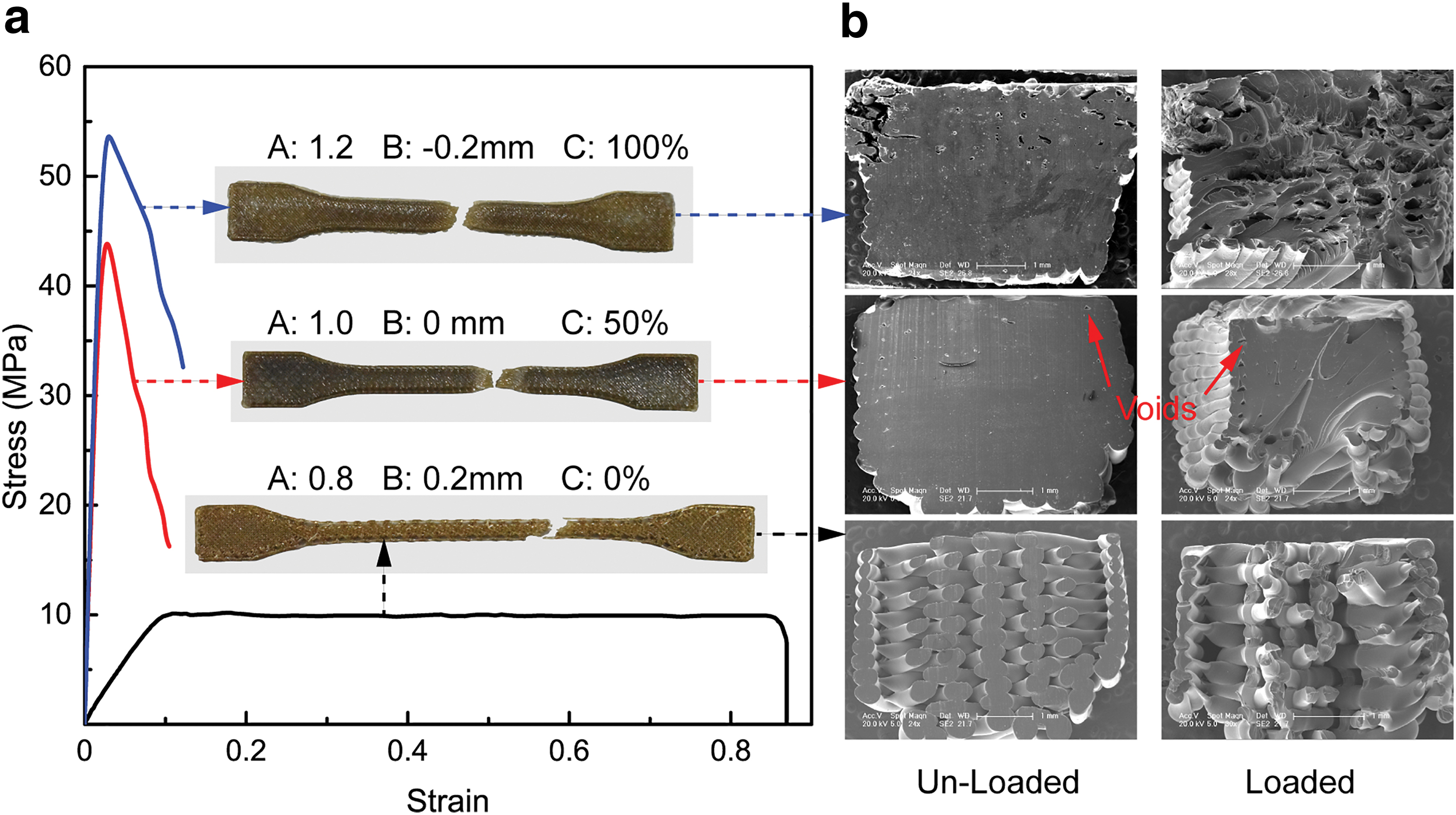
FDM PPS tensile samples for tensile strength under different extrusion parameters.
Comparison of cross-sections of unloaded and loaded samples reveals that the filaments were rotated close to 45° and parallel to the loading direction for A = 0.8, B = 0.2 mm, and C = 0%. This rotation was mainly caused by the faint interaction between adjacent filaments, which led to insufficient stiffness to resist torsion with increasing tensile loading. This phenomenon in fracture behavior was consistent with the good extensibility shown in the stress–strain curve. The curve consisted of three distinct regions: a linear elastic region, a plateau of roughly constant stress, and a final region of steeply rising stress. With increasing tensile loading, the microlattice structure comprising adjacent filaments reached a critical stiffness, and then, slippage of the lattice structure occurred accompanied by filament elongation and interface debonding of the interlayer. It can be concluded that the samples with high break elongation were dominated by the microlattice structure under low melt extrusion conditions rather than by inherent material properties. With increasing melt extrusion, the outer contour of the filament could not be distinguished. It is noteworthy that a uniform distribution of microvoids was observed between the outline and infill filament for an extrusion multiplier of 1.0, raster gap of 0, and outline overlap rate of 50%. A further increase in stress enabled these initial voids to propagate through interlayer fracture, resulting in stress concentration and leading to sample fracture. Under higher melt extrusion parameters, the inherent material properties become crucial factors dominating the mechanical properties of 3D printed PPS samples.
The maximum tensile strength of the 3D printed PPS samples was achieved for A = 1.2, B = −0.2 mm, and C = 100%; however, the dimensional accuracy was reduced and surface morphology worsened. These results were mainly due to the excessive melt supply, which resulted in disorganization of the filament arrangement and extra extruded melt flowing along a direction perpendicular to the movement of the nozzle. In conclusion, the extrusion multiplier and raster gap were the main factors affecting tensile properties of the 3D printed PPS sample. The effect of the outline overlap on tensile strength only had a slight significance.
Figure 5 presents the stress–strain curves for FDM PPS bending samples. The failure mode changed with higher melt extrusion and lower outline overlap, transitioning from a ductile fracture behavior to a brittle fracture behavior. Table 4 shows that the outline overlap had a slight significance on the bending strength. This parameter mainly maintained the outer contour of the 3D printed samples under loaded condition and the connection of the contour and infill filament. As mentioned above, comparisons of the fracture behavior confirmed that the extrusion multiplier and raster gap were the dominant factors determining the bending strength. Appropriate selection of melt extrusion parameters will thus enable improvement of the mechanical properties and suppression of defects.
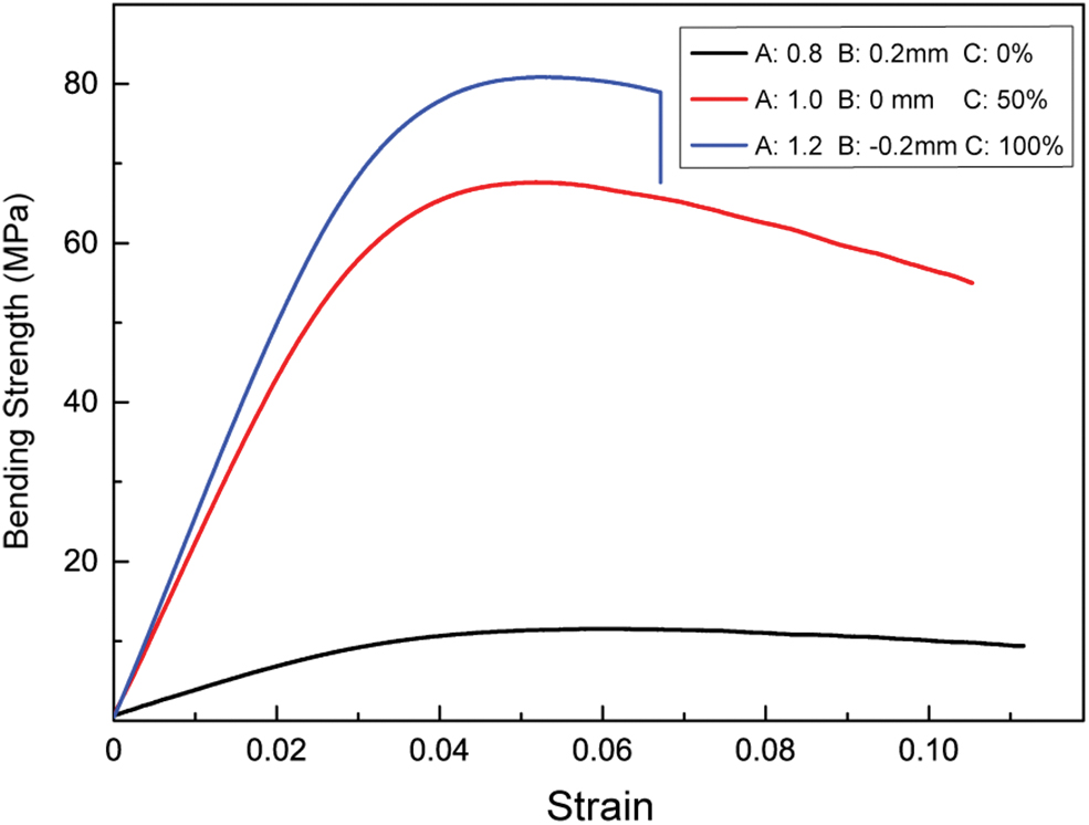
Stress–strain curves for bending strength. Color images are available online.
Figure 6 presents SEM images showing the impact fracture of 3D printed PPS samples with different extrusion parameters. The red and yellow arrows indicate the Z-direction and load direction, respectively. In general, a low extrusion multiplier, high raster gap, and low outline overlap resulted in increased impact strength. For A = 1.2, B = −0.2 mm, and C = 100%, cracks initialized and grew along the impact direction, leading to a tendency for cracks to span dozens of successive print layers. With the incorporation of voids, the residual porosity provides a new source of crack propagation. In addition, the 3D printed sample exhibited high crack-susceptible behavior. For A = 1.0, B = 0 mm, and C = 50%, the residual porosity prevented the cracks from extending through multiple layers, which is inconsistent with the previous condition. The filament cross-section exhibited cleavage fracture morphology, and the cracks extended through the interfaces of adjacent filaments, thereby revealing a substantial difference compared with the previous condition. For A = 0.8, B = 0.2 mm, and C = 0%, the bonding interface was insufficient to constrain filament movement, and the filaments exhibited a series of localized necking and diffusion.
SEM fracture surface morphology of FDM PPS impact samples show the crack originals and impact expansion regions.
Effect of filament alignment parameters on the strength of formed samples
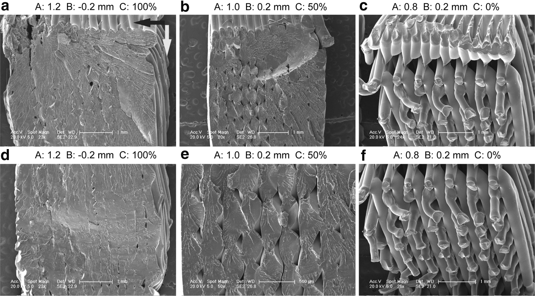
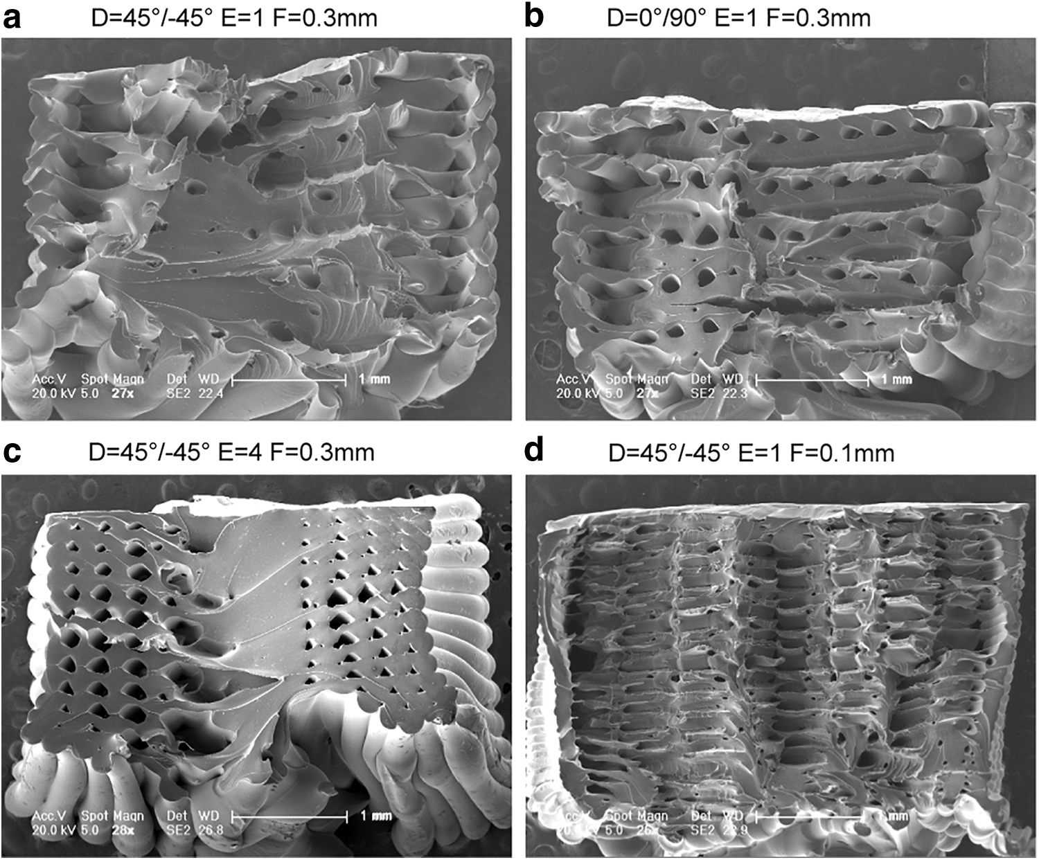
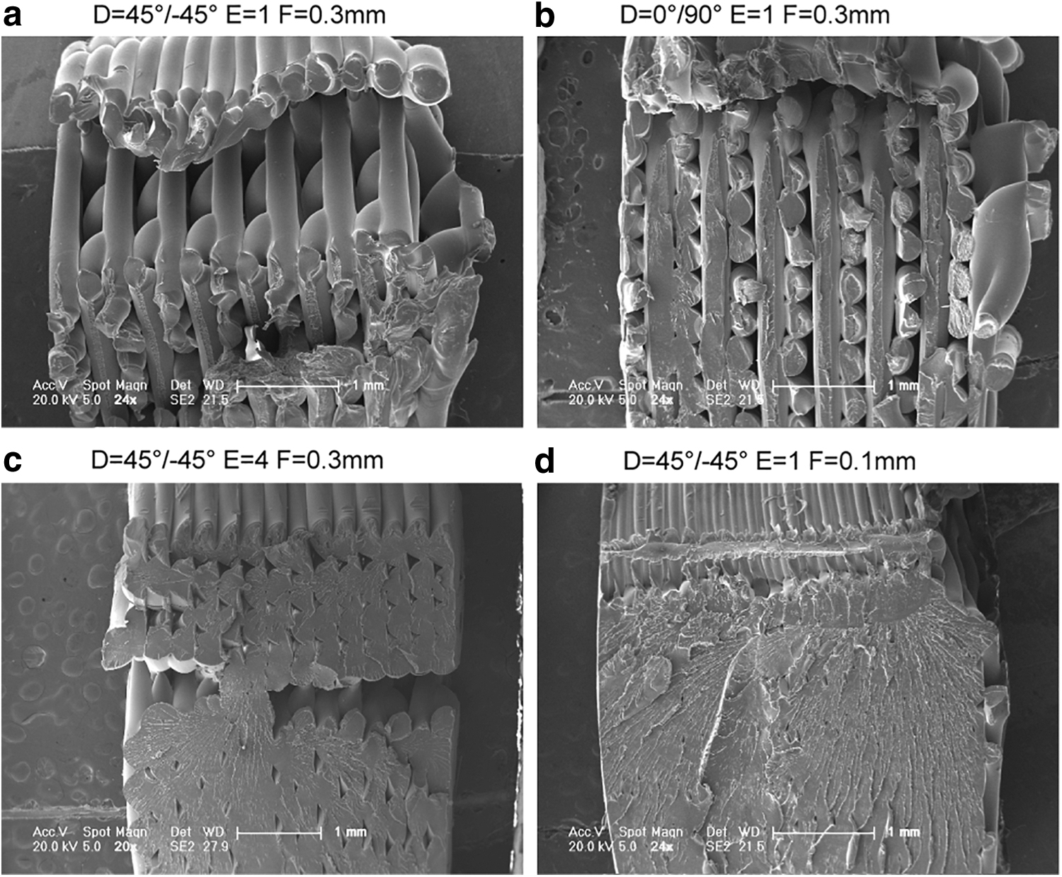
Figure 7 shows tensile, bending, and impact properties of 3D printed PPS samples for different filament alignment parameters. Figures 8 and 9 present SEM images of the tensile and impact fracture surfaces. Figure 7 shows that the tensile and bending strengths of 3D printed PPS samples were 41.4 and 65.1 MPa, respectively, for the infill angle of 0°/90°. When the filling angle was 45°/−45°, the maximum impact strength was 13.3 KJ/m2. The fracture morphology changed with increasing infill angle, as shown in Figure 8. The tensile and bending strengths were dictated by tensile and shear loads in the axial and radial directions of the filament, respectively. The failure mode changed from tensile failure of the filament to debonding of the adjacent filament. Figure 9a and b shows that differences in fracture behavior can be primarily attributed to the orientation of the cubic microlattice structure in the fracture morphology of 3D printed, PPS impact samples. When the lattice was perpendicular to the impact direction, the interfaces between adjacent layers were low enough to allow dislocation. In contrast, when lattices were printed under other infill angles, the impact energy absorption was attributed to stretching of filaments and lattice distortion.
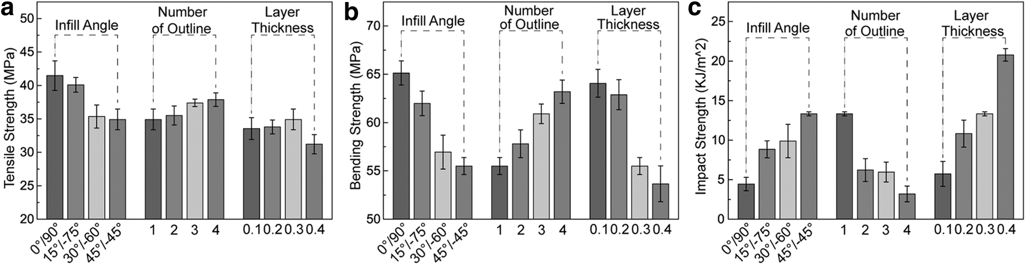
Average maximum mechanical strength of FDM PPS samples printed using different filament alignment parameters.
SEM fracture morphology of FDM PPS tensile samples.
SEM fracture morphology of FDM PPS impact samples.
The effect of the number of outlines on mechanical properties is shown in Figure 7. The maximum tensile, bending, and impact strengths were 37.9 MPa, 63.2 MPa, and 13.3 kJ/m2, respectively. As discussed above, filament orientation is directly related to the mechanical strength and is crucial to the fracture behavior. In fact, the effect of the outline on mechanical properties is analogous to that of the filament parallel to the loading direction. Therefore, there was a significant improvement in the tensile and bending strengths with increasing number of outlines.
The effect of the layer thickness on mechanical properties is shown in Figures 8 and 9c and d. The maximum tensile, bending, and impact strengths were 34.9 MPa, 64.1 MPa, and 20.78 kJ/m2, respectively. Reducing the layer thickness means that the filament is extruded in a more stable and exact manner without increasing the melt extrusion mass, leading to improved filament bonding strength and uniform distribution of porosity. More uniform distribution of filaments and higher bonding strength are thought to improve the strength and stiffness of the shell of 3D printed parts. In contrast, porosity remains nearly constant with the result of no significant reduction in tensile strength. Likewise, a smaller layer thickness limits filament elongation and slippage of the lattice structure during the impact process.
Conclusions
PPS, an ideal special engineering plastic with high performance and low cost, has great potential to be widely used as an FDM material. In this work, we studied the effects of the melt extrusion parameters (extrusion multiplier, raster gap, and outline overlap) and filament alignment parameters (infill angle, number of outlines, and layer thickness) on the tensile, bending, and impact properties of FDM PPS samples. A higher mass of melt extrusion was shown to be beneficial for increasing the tensile and bending strengths and reducing the residual porosity of FDM PPS samples. However, the impact samples exhibited lower impact strength because of the brittle behavior and limitation of microlattice structure movement.
The mechanical properties of 3D printed PPS samples were also affected by the filament alignment parameters. For a filling angle of 0°/90° and number of outlines of 4, higher tensile and bending strengths and lower impact strength were observed. The mechanical properties were dictated by the filament direction and slippage of the microlattice. The higher bonding strength and uniform distribution of porosity associated with decreasing layer thickness were beneficial in improving the bending strength, but restricted filament elongation and slippage of the lattice structure during the impact process. Fabricating PPS parts using these optimized parameters will enable the realization of 3D printed PPS parts with a diverse range of mechanical properties.
Footnotes
Author Disclosure Statement
No competing financial interests exist.
Funding Information
This research is supported by the National Natural Science Foundation of China (no. 51675226); Key Scientific and Technological Research Project of Jilin Province (no. 20180201055GX); Project of the International Science and Technology Cooperation of Jilin Province (no. 20170414043GH); and Industrial Innovation Project of Jilin Province (no. 2019C038-1).