
Abstract
Laser powder bed fusion (LPBF) is a promising technology that requires further work to improve productivity to be adopted more widely. One possible approach is to increase the laser power and scan speed. A customized high-speed and high-power LPBF system has been developed for this purpose. The current study investigated the surface roughness and near-surface porosity as a result of unsupported overhangs at varying inclination angles and orientations during the manufacturing of Ti6Al4V parts with this custom high-speed and high-power LPBF system. It is known that surface roughness and porosity are among the main drawbacks for parts manufactured by LPBF, and that supports are required for overhang regions with low inclination angles relative to the powder bed, typically in commercial LPBF systems requiring supports for regions with inclination angles less than 45°. However, the appropriate inclination angles for this custom system with high power and speed requires investigation. In this article, a simple benchmark test artefact with different inclination angles was manufactured in different orientations on the build platform and characterized by X-ray tomography, touch probe roughness meter, optical microscopy, and scanning electron microscopy. The analysis of surface roughness and near-surface porosity at upskin and downskin regions was performed as a function of inclination angle. The results indicate that the high-speed LPBF process produces relatively high roughness in all cases, with different porosity distributions at upskin and downskin areas. Both roughness and porosity vary as a function of inclination angle. Significant warping was observed, depending on build orientation relative to laser scanning direction. These are the first reported results of the detailed surface roughness and porosity characterization of part quality from such a high-speed, high-power LPBF process.
Introduction
Laser powder bed fusion (LPBF) is an additive manufacturing (AM) technique that entails the consolidation of predeposited powder layers by laser beam to form 3D objects. The key objective of the LPBF process is to create complex metal parts directly from a CAD model with minimal defects. At optimal process parameters and scanning strategies, fully dense objects can be produced with mechanical properties comparable to, or even higher than, those created by traditional methods.1–3
The layer-by-layer nature of the LPBF process causes limitations on accuracy, fine features and roughness of LPBF parts: changing any parameters, that is, laser power, spot size, scanning speed, hatch distance, scanning and building strategies, or properties of the powder contributes to the density, accuracy, and surface roughness.4–8 High-temperature gradients and cooling rates lead to high stresses and associated risk of distortions: parts might be warped during or after processing. Support structures are often used to mitigate the warping risk for overhanging areas: they act as anchors, serve as heat dissipators, and prevent thermal warping of the parts. 9
Design of support structures and sample orientation in the build platform influence the amount of deformation, build time, and support removability of AM parts. 10 However, excessive utilization of support structures has a direct implication on powder consumption, build, and postprocessing time and leads to high roughness after support removal, leading to more post-processing costs.11,12 On the other hand, some investigations showed that supported specimens exhibited significantly higher fatigue strength than the unsupported specimens. 13 Manufacturing of complex parts with overhanging regions without supports can lead to dross formation (very rough downward facing surfaces). In extreme cases, deformation during processing can cause redistribution of the powder, which results in porosity and increased roughness of the surfaces, or even build failure. It is, therefore, of high interest to find ways of building LPBF specimens without supports but with improved properties.
The mechanical behavior and especially fatigue properties of parts depend on the material, microstructure, porosity, and surface roughness, among others.14,15 Very rough surfaces may be detrimental to especially fatigue properties, because rough surface features can act as effective notches, which lead to stress concentration sites and subsequent crack initiation under cyclic loading conditions.16–18 For the downskin areas (at overhangs, down-facing surfaces), the surface roughness is typically higher than up-ward facing and vertical walls, but the relative roughness variation depends on all the processes mentioned earlier and LPBF system parameters. This, coupled with the requirement to produce parts where surfaces cannot be machined or smoothened on complex or hidden surfaces, makes it important to characterize and optimize the surface finish for as-built parts.
Previous studies have highlighted that, in components with overhangs, there exists a critical angle toward the build plate that requires support structures and an angle greater than this critical angle (e.g., 30°) can be built without support structures. 8 However, parts produced with angles <45° generally possess poor surface quality due to heat accumulation that results in powder agglomeration on the underside.8–19 The stair-stepping effect also contributes to poor surface roughness and becomes more pronounced at angles lower than 45°. 12 By determining the minimum support angle, the use of a solid support structure is not required up to a certain point. 20 The development of AM processes, which allows to design and print complex geometric shapes with overhang surfaces below 45° without the need for supports and having improved surface qualities, is certainly in demand and important. Successful development in this direction is already underway. Velo3D developed the process “Intelligent Fusion,” which includes special software, closed loop control, and a special noncontact powder recoating mechanism. 21 This approach can make significant progress in the quality of LPBF parts with overhanging surfaces at low inclination angles. However, this process is not widely available so more studies are needed to fully characterize its advantages.
It was shown that in “traditional” LPBF systems with contact powder delivering system, including blades or rollers, the variability of surface roughness was more pronounced at the periphery of the build platform where the gas inlet/outlet is placed and close to the start of the recoating process than at the center. 22 Thus, surface roughness can depend not only on building and scanning parameters and strategies, and powder properties, but also on the recoating system and gas flow.22–24
As previously reported in Ref., 25 the CSIR National Laser Centre (South Africa) and Aerosud Innovation Centre developed a high-speed Aeroswift LPBF system to build large Ti6Al4V parts (max 2 × 0.6 × 0.6 m). An example of a large part produced in Ti6Al4V is a large topology optimized drone frame, as shown in Ref. 26 Due to an order of magnitude of higher laser power and faster scan speeds than “traditional” LPBF systems, the properties of parts produced by this system require characterization. The process parameters have been previously optimized focusing on density of the bulk (core) of test samples. Fully dense interior of parts are produced; however the process parameters used are confidential and cannot be reported here. What can be mentioned is that the power used is 2 kW and layer thickness is 50 μm. This article reports on the characterization of surface roughness and porosity as a function of inclination angle for the optimized parameter set for this high-speed LPBF system, which is used for all its manufacturing on a daily basis. The reported images and cross-sections in this work also validate the high density for the interior of the samples. A set of benchmarking samples were designed in the form of parallelepipeds with different inclination angles and manufactured in different directions relative to laser scanning and gas flow on the Aeroswift LPBF system. Samples were characterized by a combination of surface roughness tactile probe, optical microscopy, scanning electron microscopy, and X-ray tomography. These results inform the design process for parts to be manufactured (e.g., inclination angles requiring supports, orientation relative to scan direction, etc.) and also provides information for postprocessing of critical parts.
Materials and Methods
The prealloyed gas atomized Ti6Al4V powder (grade 5) was supplied by TLS Technik. The powder particles were spherical and had equivalent diameters d10 = 22–27 μm, d50 = 35–40 μm, and d90 = 51–56 μm. Before loading into the LPBF system, the powder was dried in an oven at 120°C for 4 h to remove moisture. The Aeroswift LPBF platform used an Ytterbium fiber laser with a maximum power output of 5 kW. The parts reported in this article were manufactured with optimal parameters previously determined based on density of coupon samples, which includes a laser power of 2 kW and layer thickness of 50 μm. Other parameters are confidential, but these parameters are used for all kinds of manufacturing in this system. Before the start of the building, the chamber was filled with Ar until the oxygen value reached below 100 ppm. Samples were manufactured with a build volume rate of 30 mm3/s, which is higher than three to six times in comparison with existing industrial one-laser L-PBF systems.
The manufactured test samples are parallelepipeds with inclination angles from 25° to 90° with 5° increments. This study consisted of different sets of samples (A and B) that were orientated in the YZ plane (set A) and XZ plane (set B) (Fig 1). A back-and-forth (zigzag) scanning strategy was used during laser processing, that is, the laser beam scans all layers along the Y axis in Figure 1. In other words, scanning starts closest to the extraction and moves away from it. The protection gas flow was perpendicular to the scanning direction to extract “smoke” (evaporated material and small particles from spattering). Samples were scanned with post-contouring by using process parameters similar to the core part.
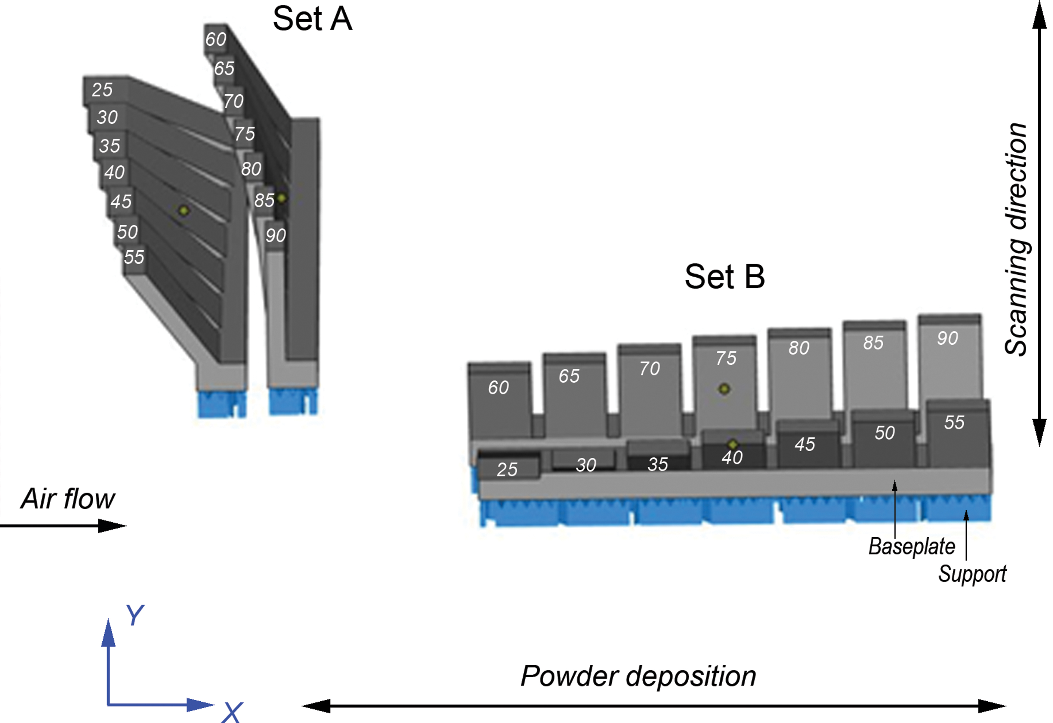
Parallelepiped samples with inclination angles from 25° to 90°. Color images are available online.
Samples were manufactured with solid rectangular baseplates, built on supports (Fig. 1): samples with 25°–55° inclination angles and with 60°–90°—on different baseplates. After removal from the supports, sets were placed in an ultrasonic bath for 10 min and then analyzed in as-built condition, without any further heat treatment or post-processing.
An analysis of the surface morphology, size, and distribution of pores is of particular interest in this work. Porosity was measured by X-ray micro computed tomography (microCT) scans in a region of interest covering 80% of the middle of the flat surface with a resolution of 20 μm. The analysis area in each case was selected for upskin and for downskin regions of interest extending subsurface up to ∼3 mm. This was done to find possible correlations between localized near-surface porosities and inclination angles. The use of microCT in AM, including its use to measure porosity and evaluate surface roughness, are summarized in the review. 27 Further, surface pores and surface roughness on the samples were qualitatively characterized by using physical cross-sections and an optical microscope.
After separation from the baseplates, the surface roughness was measured according to ISO 427:1997 by a Mitutoyo Surftest SJ-210 contact profilometer, with a Gaussian filter λc = 0.8 mm used as recommended in Ref. 28 The optical length was 2.5 mm, and all measurements were conducted a minimum of six times perpendicular to the layer direction. Average values were compared by Student's t-test (p < 0.05).
Results
Deformation and surface roughness characterization by microCT
Samples were found to be deformed after separation from the built platform (Fig. 2)—this was observed specifically on the bottom of the solid platform relative to the design in each case. In this image, the actual part by microCT scan data is shown in white and the design file is shown in transparent blue color. It is clearly seen that the actual parts had deformations. Maximum warping of 3.92 and 3.23 mm in Z-direction (upwards) was measured in set A versus 0.76 and 0.17 mm in set B. It is known that the maximal principle stress in LPBF samples develops along the scanning direction. 29 The accumulation of residual stress in samples from set A that were scanned along the long side (Y-direction, Fig. 1) explains the higher deformation in set A as compared with set B.
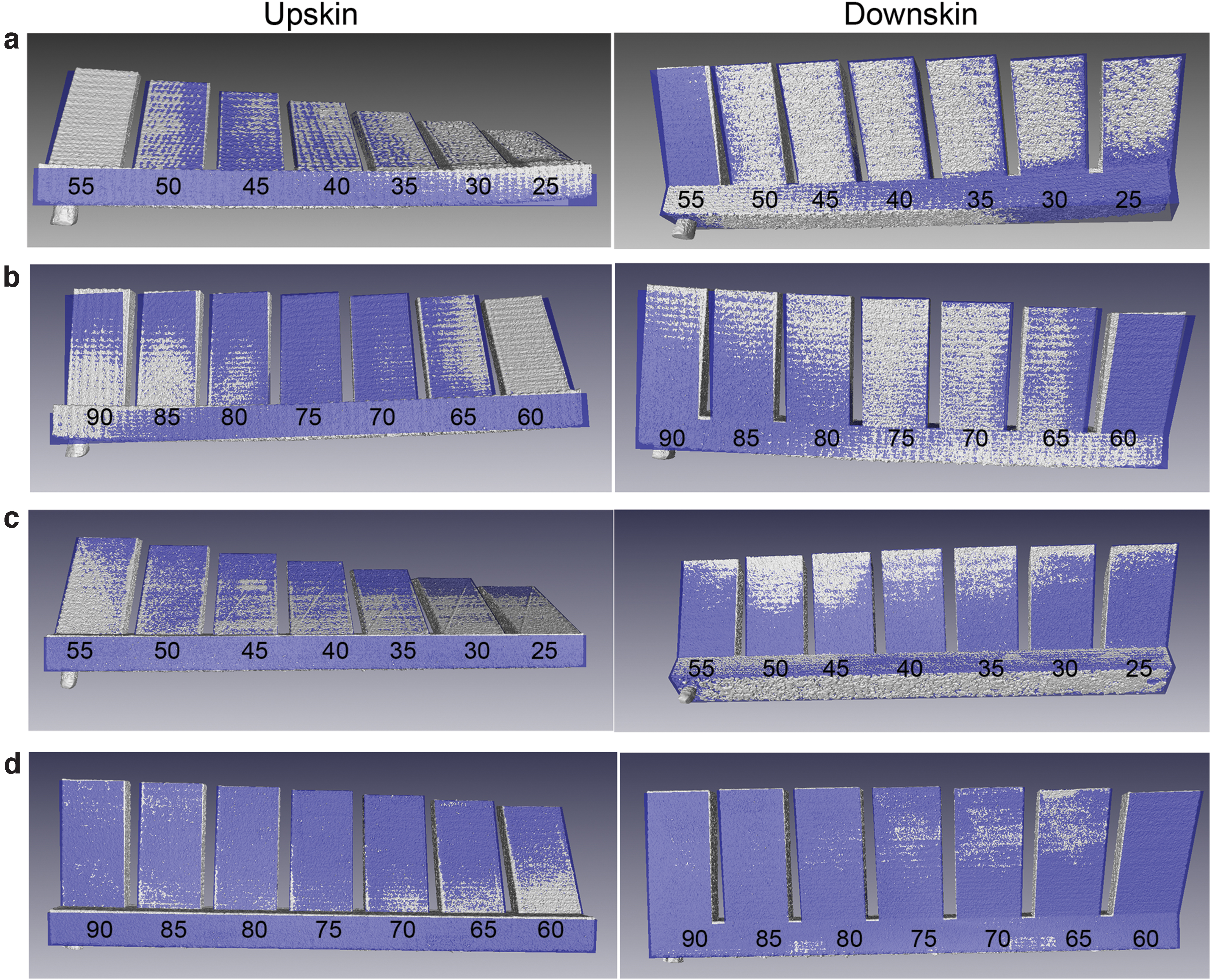
MicroCT scans of manufactured LPBF samples at different inclination angles versus designed shape coded with blue color: set A—25°–55°
A representation of the roughness of downskin surfaces for sets A and B is shown in Figure 3 as color height maps. All images have the same color coding, making a qualitative comparison possible between inclination angles and between different samples. The downskin surface images obtained using SEM for both sets A and B were in good agreement with the microCT scan observations (Fig. 3): A higher agglomeration of powder particles was observed at low angles, which improved slightly at an increased inclination angle (Fig. 4). For the upskin surface, images show that powder agglomeration had an opposite trend with inclination angle as compared with the downskin surface. Relatively smooth surfaces with clearly visible layers were observed at 25° and 30° angles; but at an angle of 90° agglomeration of sintered powder particles was observed as a dominant feature.
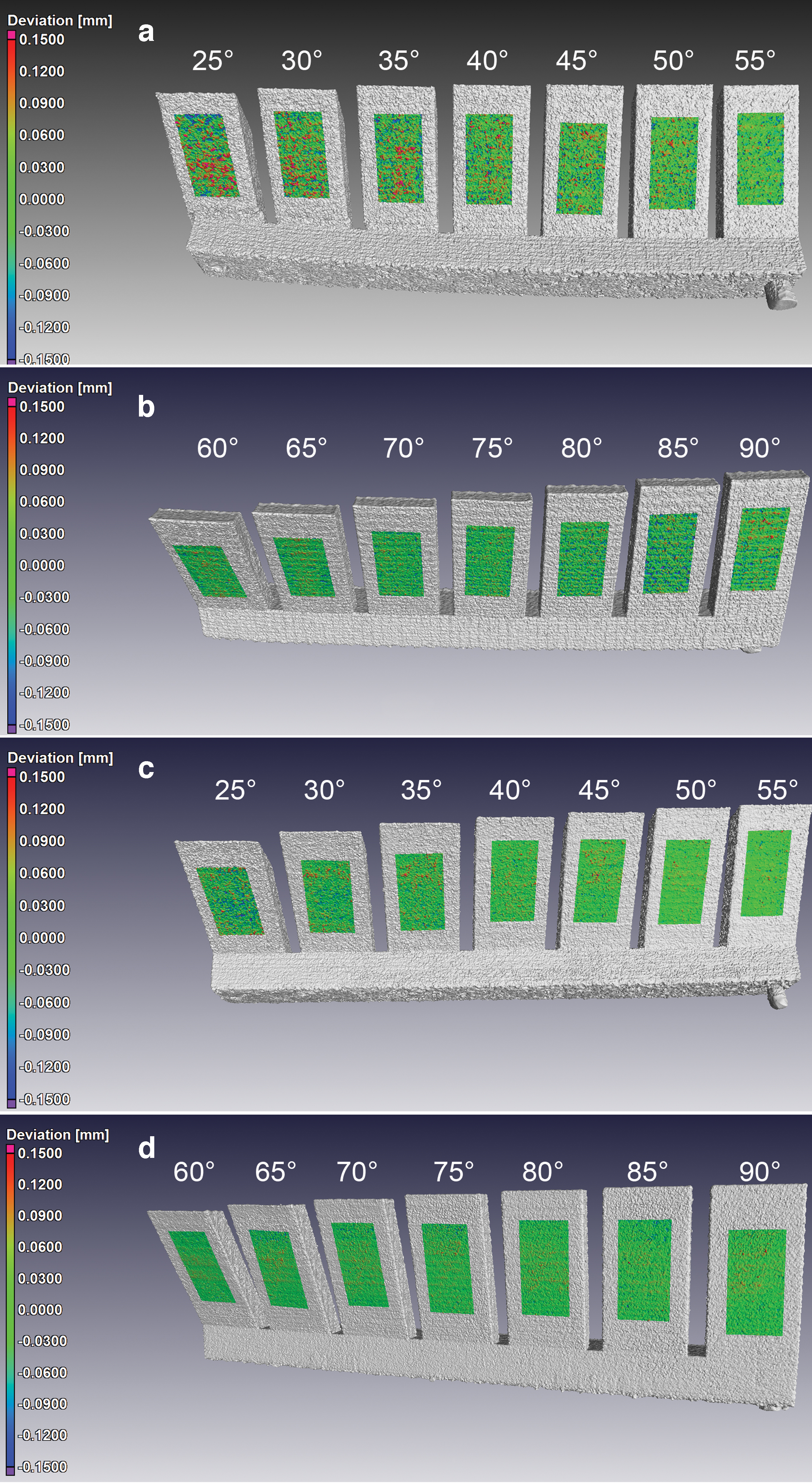
MicroCT reconstruction of downskin surfaces versus inclination angle: set A
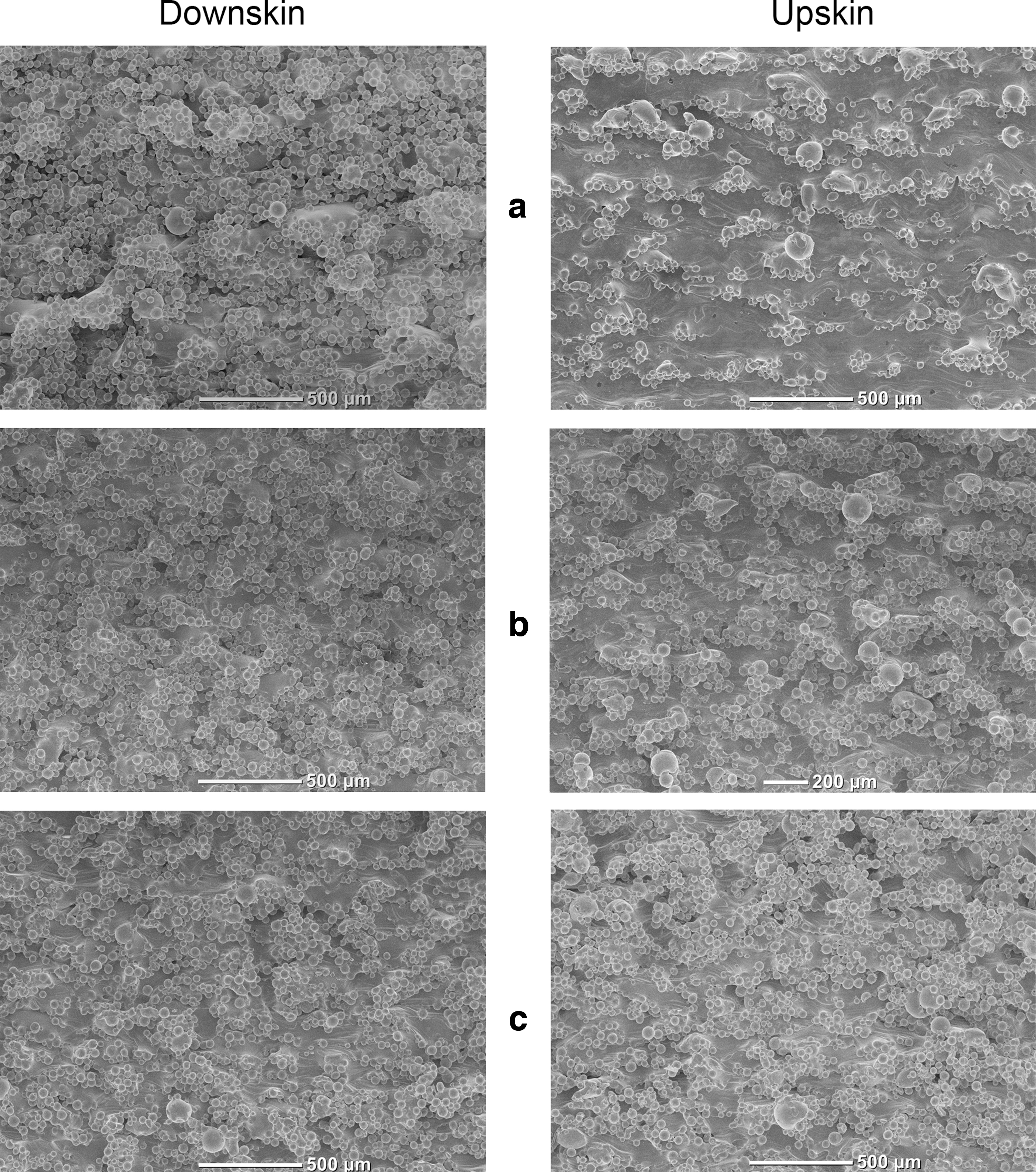
SEM images illustrating downskin and upskin surface roughness for different inclination angles of set B: 30°
Surface roughness evaluation by contact profilometer
Ra is the arithmetic mean height that defines the average roughness and Rz is the maximum height of a profile. 30 Average values with standard deviation and statistically significant differences in average values are shown in Table 1. Figure 5 shows typical profiles and cross-sections for sets A and B for surfaces against the inclination angle.

Cross-sections of samples and typical profiles obtained by contact profilometer for different inclination angles in sets A and B. Color images are available online.
R a and R z Values at Different Inclination Angles (Mean ± Standard Deviation, μm)
Statistically significant difference between average values for sets A and B (p < 0.05), t-test.
Statistically significant difference between average values for upskin and downskin (p < 0.05), t-test.
Porosity
In this section, the porosity of near-surface areas up to 3 mm below surface is discussed only, and only fully enclosed porosity is quantified. The porosity of samples near downskin surfaces was <0.1%: from 0.008% to 0.06% for set A and 0.002–0.017% for set B as microCT analysis showed (Fig. 6). For set A, downskin porosity tended to decrease with an increasing angle of inclination (Fig. 6a); a negative correlation coefficient between near downskin porosity and inclination angle for set A was found to be −0.726. Higher porosity in set A for upskin areas (up to 0.16%) was mostly due to single or a few big pores at 25°–35° and 75° inclinations (Fig. 6b, c). Surface roughness values of Ra and Rz measured by contact profilometer did not show any correlation with near-surface porosity recognized by microCT scans (Fig. 6c).
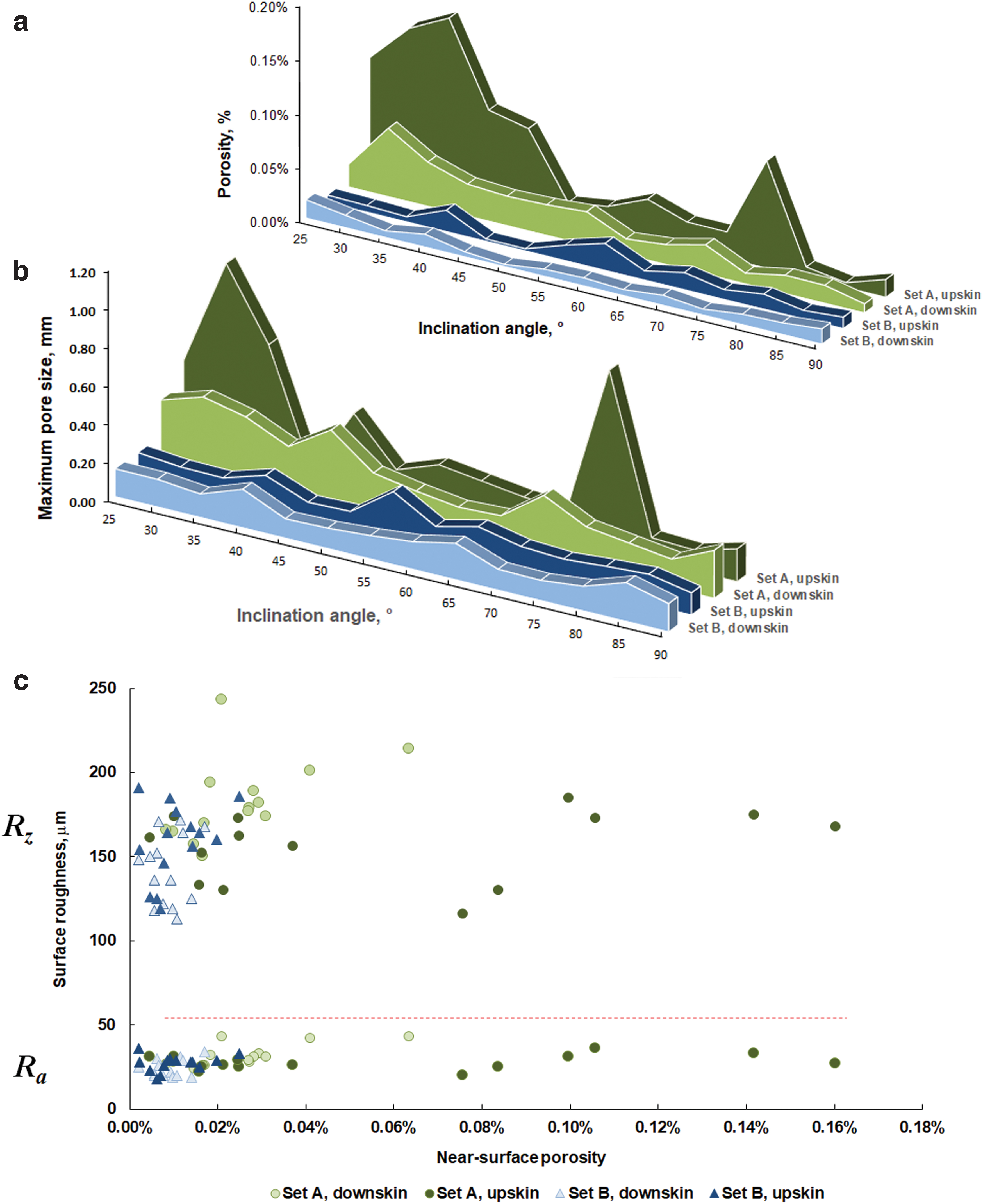
Porosity of the samples near the surface
Figure 7 shows a visual comparison of upskin and downskin regions, for surface roughness together with near-surface pores, obtained by using microCT scans and cross-sections for the inclination angle of 35°. For downskin surfaces, the orientation of a part combined with the low overhang angle was found to contribute not only to high surface roughness, but also to the formation of pores closer to the surface.
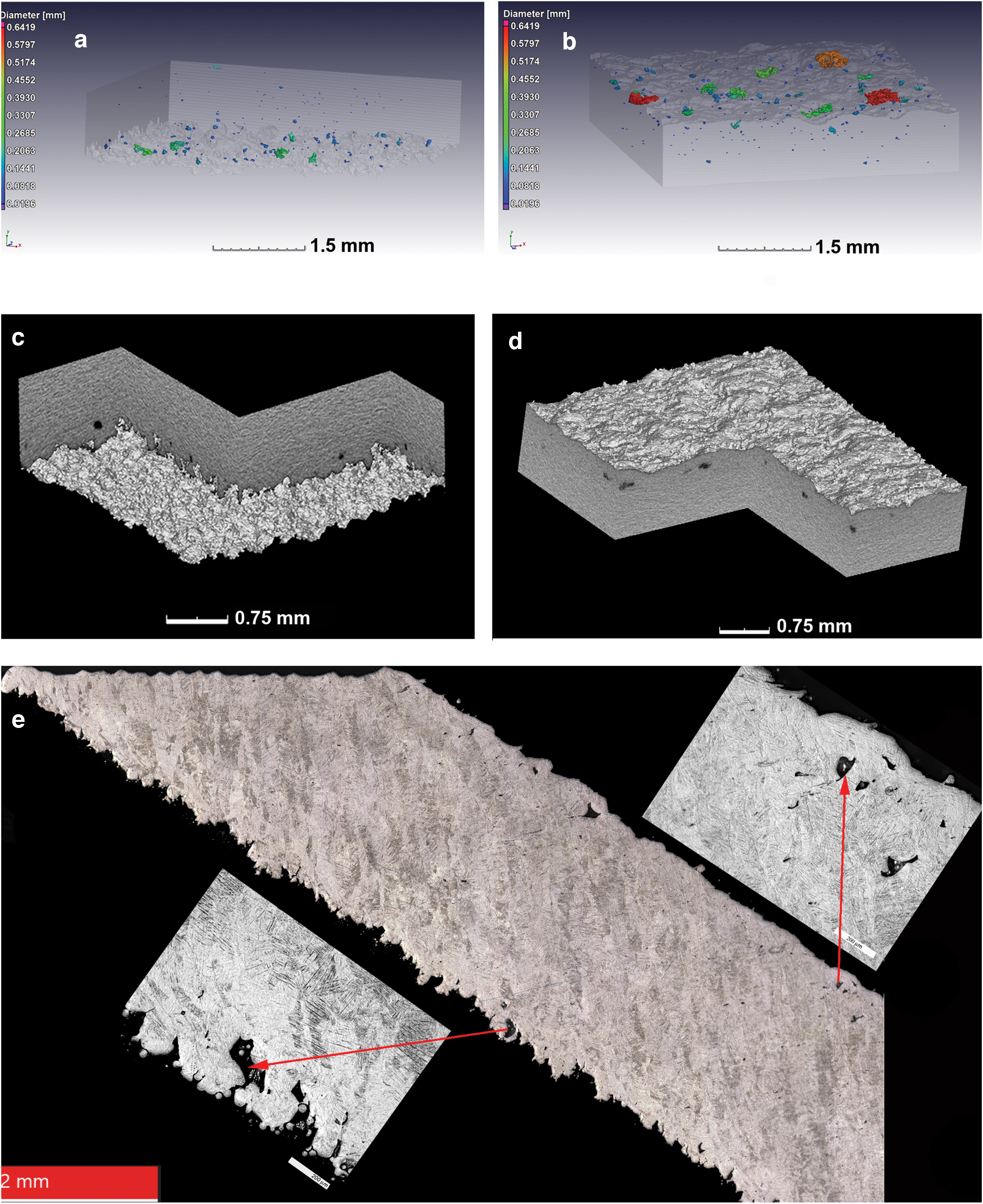
CT scans of samples from set A at inclination angle of 35°: near downskin
Discussion
The roughest surfaces were found in low-inclination angles and especially more in set A. Surface roughness measurement using similar procedures by microCT data were demonstrated in Refs.28,31 In this work, for simplicity and to directly compare with results from other research works obtained on additively manufactured surfaces, a standard contact profilometer was used for quantitative evaluation of the surface roughness. In set A, opposite linear trends for downskin and upskin surface roughness were found: The downskin roughness improved and upskin surfaces deteriorated as the sloping angle increased. Overall, the upskin surfaces were less rough than downskin ones, but they had evident waviness at low inclination angles, as shown by cross-sectioning (Fig. 5). This is to be expected as the downskin roughness can be mainly attributed to the stair-stepping effect for angles lower than 45°, and also because the downskin surface directly solidifies on top of loose powder particles, as illustrated schematically in Figure 8. However, for angles greater than 45°, roughness is increased due to trapped powder particles that adhere to the surface during laser processing, which contributes to the increased surface roughness values. This agrees with the findings in Covarrubias and Eshraghi 12 and Cabanettes et al. 32 that parts manufactured by the LPBF process with angles <45° are greatly influenced by stair-stepping effect. For set B, the roughness for the downskin surface also slightly decreased with an increasing inclination angle, but upskin roughness had no similar trend: Quite low Ra were found at small inclinations and maximum values were found in 50° (with high deviation) and 60° samples.
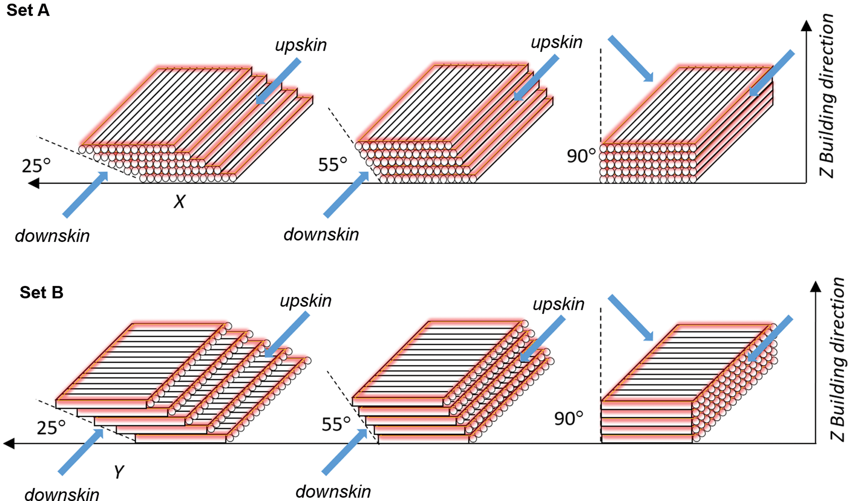
Scanning strategy and stair-stepping effect with inclination angle for sets A and B: Postcontours are indicated by red color, and analyzed surfaces are shown by blue arrows. Color images are available online.
From Figure 8, it is clear that at low inclination angles, the stair-step effect is expected to be prevalent and this defines the morphology of the surfaces of LPBF parts, and the attached particles contribute less to the roughness. This is especially true for upskin surfaces, as confirmed in Figures 4 and 5. When the slope is increased, the stair-step edges become smaller, thus leading to a higher contribution to the roughness by partially sintered particles—resulting in poor surface quality for vertical samples.
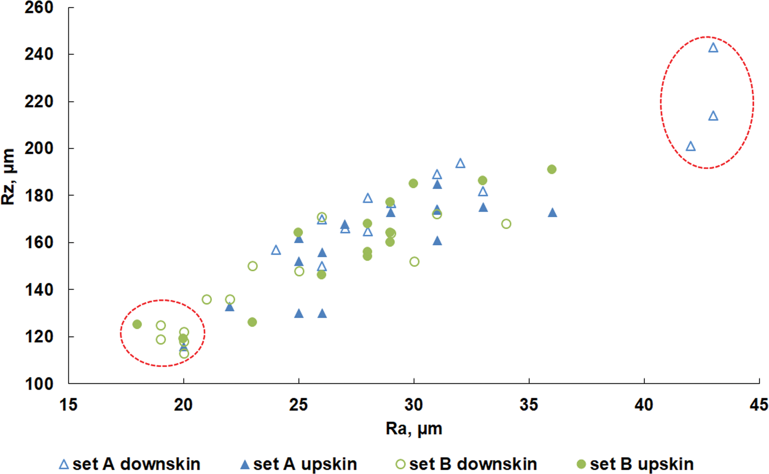
The maximum height Rz covers surface irregularities such as the individual peaks and valleys on the samples. The highest values were found in set A at inclination angles of 25°–35° for downskin surfaces; minimal roughness was at similar slopes in upskin surfaces for set B (Table 1). Rz values had high correlation with Ra values, with Pearson's coefficient of 0.8–0.9 (Fig. 9).
Average surface roughness parameters Ra and Rz for downskin and upskin surfaces. Color images are available online.
For comparing these roughness values with “traditional” LPBF processes as reported in the literature, some examples are mentioned here. In a study where the laser power was in the range of 75–150 W and powder layer thickness 30 μm, the maximum Ra did not exceed 20 μm. 33 At optimized process parameters for Ti6Al4V samples were produced on an EOSINT M280 system, the measured Rz of vertical side surfaces was in the range of 56–135 μm.2,34 For 45° inclination angle Ra and Rz for upskin surfaces these values were about 15 and 77 μm correspondingly. 34 Ti6Al4V samples at 45° and 90° produced on an SLM 250 HL machine (SLM Solutions) at a layer thickness of 50 μm, with laser power of 275 W and 0.975 m/s with contouring, resulted in Rz 103–115 μm for upskin surfaces. 35 In the present study, for high-speed laser beam with high laser power and layer thickness of 50 μm, even for upskin surfaces, attached particles were a highly influencing factor for surface roughness and Rz and Ra was almost twice higher than these typical LPBF systems.
At high energy input, the denudation zone of powder is also wider and a high volume of material is involved in single track formation.36,37 It was shown that at high laser power, when evaporation was not very pronounced, a long molten pool provoked capillary instability of the solidifying track. 38 An increased volume of the molten pool induced intensive flows, which led to instability in the liquid phase and resulted in irregularities in the solidified tracks, which resulted in the formation of irregular and rough layers. In addition, for overhanging surfaces, poor surface quality can be attributed to partial melting of surrounded powder particles caused by the lack of heat dissipation on overhanging areas, coupled with the high temperatures induced by the process.39,40
The orientation of the samples relative to gas flow and laser scanning direction had an effect on the roughness. All samples were scanned back and forth in the Y direction, with postcontouring. In analyzed surfaces, the contour was parallel to the melted tracks for set A, and it was perpendicular to them in set B.
For set A, the roughness was formed by lateral sides of the scanned tracks; in set B, the start and end of the tracks defined the morphology of the studied surfaces, despite the contouring applied (Fig. 8). The bottom parts of single tracks were associated with the downskin surface, and the upper parts of single tracks were associated with upskin surfaces in both sets. When comparing the difference in downskin roughness for set A and B (Table 1), at an angle of 25° set A had an average roughness value Rz of 243 μm compared with set B, which had a roughness value of 173 μm. A similar observation can be made at higher angles, that is, 55°, whereby set A reports a roughness of 174 μm whereas set B reports a roughness of 130 μm. In Ref., 32 a similar effect was found where partly melted particles were mainly attached to the lateral parts of the tracks in the layer in comparison with the alternative layer scanned in the perpendicular direction. In the present study, the difference can be attributed to the scanning strategy and orientation of the sample on the built platform (Figs. 1 and 8). As shown in Ref., 41 at high laser power, molten material is pushed down into the underlying powder layers by recoil pressure from strong vaporization. Deep penetration into loose powder and instability in the longer hotter melt pools 41 formed on the loose powder, creating a dross on the downward surface. At the high scanning speed used, the humping effect and spatter ejection originated from vapor-driven entrainment of micro-particles by an ambient gas flow, 42 which contributed to the upskin surface morphology for both sets.
In set A, high porosity near the upskin surfaces also was found (Fig. 7b). As mentioned earlier, in this set upskin surfaces were formed by the lateral part of the melted tracks. It was shown in previous work that at high scanning speed, unstable tracks with many satellites can contribute to lateral pore defects. 43 The unstable tracks led to irregular-shaped flattened pores under surface at the upskin area. This is visible in Figure 7d and e. The near-surface pores at downskin and upskin surfaces are also shown in a physical cross-section in Figure 7e.
Analysis of cross-sections showed that many randomly distributed fusion pores were found in the core part of the samples and they were not clear at the 20 μm scan resolution for microCT scans. These are shown in cross-sections, with pores highlighted in red circles in Figure 10. The formation of these defects with a flattened shape in the build plane can be attributed to the high scanning speed used by the Aeroswift platform to increase LPBF productivity. As shown in Ref.,44–46 the instability of the molten pool as a result of the high scanning speed can lead to noncontinuous tracks and humping effect and form layers with high roughness. Qiu et al. 5 also postulated that splashing of molten material is more pronounced at increased laser scanning speeds, thus affecting next-layer deposition, resulting in uneven layers, and leading to continued layer instability and formation of pores in 3D parts.
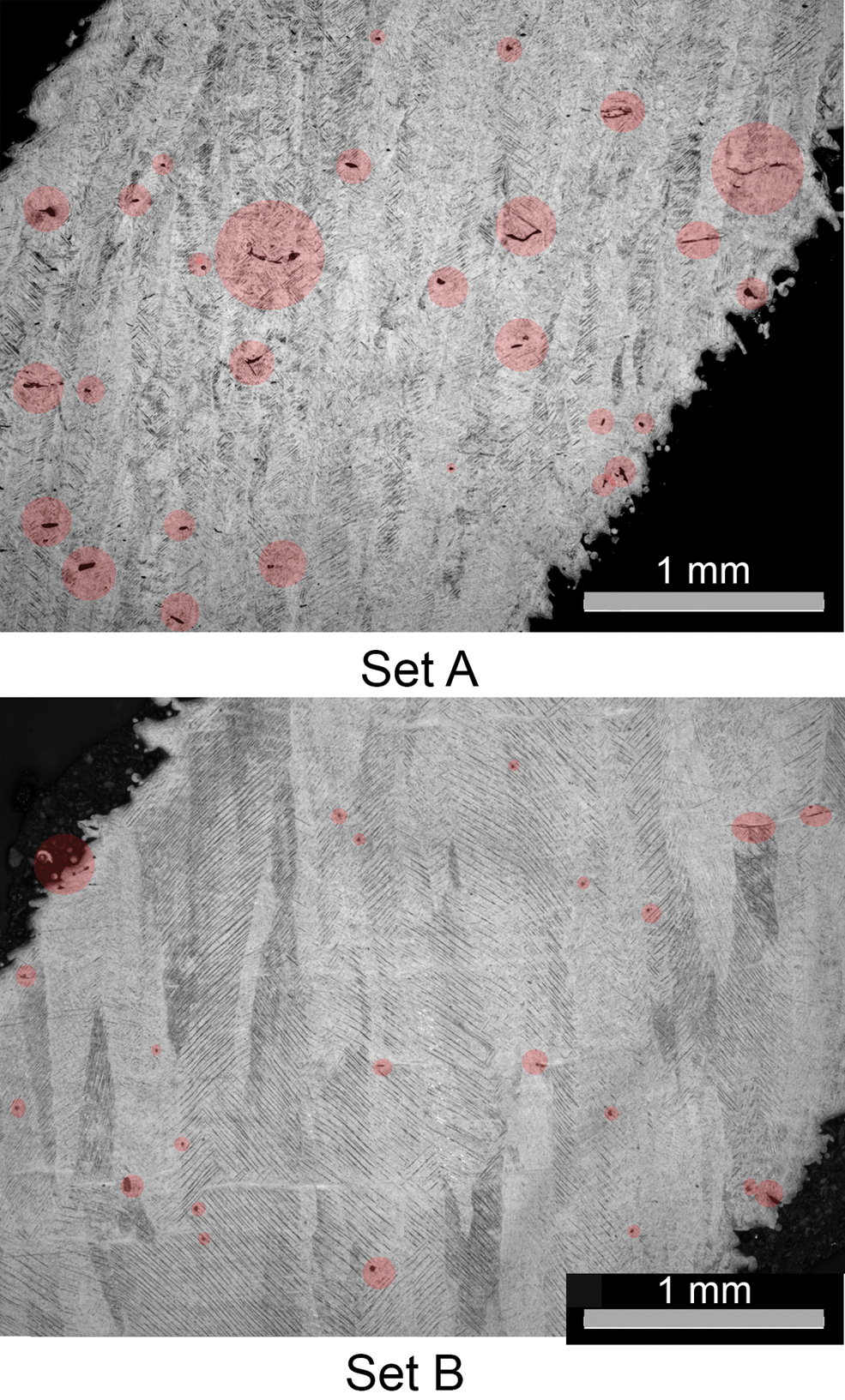
Cross-section of the samples manufactured at 55° angle. Some pores are indicated with red color. Color images are available online.
Conclusions
This study compared the effect of inclination angles on deformation, upskin and downskin surface roughness, and near-surface porosity of LPBF parts produced by the high-speed Aeroswift system, from Ti6Al4V powder with fixed process parameters. Deformation of solid blocks with attached rectangular samples indicates high residual stress depending on build orientation relative to scan direction—this can be attributed to the high temperatures in the process. To decrease this deformation, it is necessary to further optimize the scanning strategy, to disorientate the stress build-up. Overall, the total porosity was reasonably low; however, a lack of fusion pores was found, which can potentially deteriorate mechanical properties. High surface roughness for downskin and upskin surfaces at all inclinations was found, with roughness mainly attributed to the attachment of particles due to the high temperature during processing, with contributions also from the staircase effect, and irregular unstable tracks caused by the high scanning speed. Optimization of surface roughness might be possible by an appropriate scanning strategy to reduce thermal build-up. Contouring strategies with lower power and scanning speed might also be beneficial to reduce this particle attachment. Interesting results were found with regards to near-surface porosity at both downskin and upskin regions, with variations found due to different underlying causes. The results provide useful information for further optimization of high-speed, high-power LPBF processes, working toward high-productivity LPBF systems.
Footnotes
Author Disclosure Statement
No competing financial interests exist.
Funding Information
This work is based on the research supported by the South African Research Chairs Initiative of the Department of Science and Technology and National Research Foundation of South Africa (Grant No. 97994) and CPAM Program.