
Abstract
This work details a polyolefin-elastomer-based binder system to prepare fused filament fabrication (FFF) filaments and print cores for coils for electrical engines. The processability, homogeneity, and thermal properties of the polyolefin-elastomer-based filaments are explored. A two-step debinding and sintering process was established for manufacturing dense iron parts. Results indicate the developed filaments possess superior printing and sintering (at 900°C) performance, yielding only 20% weight loss by polymer decomposition and 14 vol.% shrinkage. This indicates that the FFF technique potentially enables printing of innovative electric motor designs. The designed FFF filaments could be loaded with 80 wt.% Fe powder while keeping a decent melt-viscosity for the printing process. Due to the high metal loading, dense iron parts could be sintered without bending or deformation.
Introduction
According to ISO/ASTM 52900, additive manufacturing (AM) technology is a process of joining materials to generate parts from CAD models layer-by-layer. Benefiting from layer-upon-layer building, AM challenges conventional manufacturing techniques, especially in fabricating sophisticated structures. 1 Seven AM classes have been defined, including: Material Jetting, Material Extrusion, Binder Jetting, Sheet Lamination, Direct Energy Deposition, Vat Photopolymerization, and Powder Bed Fusion. Particularly, Powder Bed Fusion technologies such as Electron Beam Melting or Selective Laser Melting have become popular for metal printing in recent years. 1 However, some challenges hinder more widespread adoption of Powder Bed Fusion technologies. For instance, available AM powder materials are still limited to the most popular used metal alloys such as Ti64 or 17-4PH SS, high temperature gradients during the laser sintering process cause micro-structure issues and anisotropic and unpredictable mechanical performance.2–4 In addition, stress can appear in manufactured parts1,5 and changing powder materials is labor intensive and requires extensive personal safety protection equipment.
Alternatively, Fused Filament Fabrication (FFF), an AM Material Extrusion technique, is a flexible and economical technique that can be used for manufacturing all kind of materials. It is popularly used for printing polymers and polymer-composites6–8 by several industrial sectors such as the medical sector,9–11 in aviation, 1 or in automotive sectors.1,12–14 More than 420,000 FFF printers were sold in 2016, in comparison to 66 in 2007. 1 Of these, about 50% of printers were sold for industrial use. 1 The significant change in the number of sold FFF printers is mainly due to their beneficial economical acquisition costs, excellent reliability, wide range of material selection, and even multimaterial printability.
Numerous FFF filaments have been recently developed for metal or ceramic printing, such as Cu, stainless steel, and Al2O3 or with fibers, such as glass fibers for reinforcement of polymer.6,7,14–18 These filaments are printed as composites and the material performance is strongly dominated by the performance of the polymer matrix. 14 Several polymers have been proven to be effective polymer-matrix systems when making composite filaments [like acrylonitrile butadiene styrene,6,15,19 polylactic acid,7,20 nylon,17,21 and polyamide16,22,23]. However, significantly fewer composite filaments were developed for printing and sintering dense metal parts.
Hence, in this article, we explore the production of an iron (Fe) composite filament, subsequently printed and sintered, to produce dense Fe parts for electrical devices such as electrical motors. To our knowledge, little research has been done to develop Fe filaments for electromagnetic applications. This work details results of FFF-based Fe part printing by using a polyolefin-elastomer-based binder and incorporated irregular-shaped Fe powder (<45 μm) as filler material, wherein the polyolefin served as a backbone during the debinding process and the elastomer is known to improve the flexibility of filament.24–26 A mixture of acetone and heptane was employed as a solvent during the solvent debinding. Finally, filament structure and magnetic properties of printed and sintered Fe parts for the potential applications as magnetic cores for electrical motors were investigated.
Materials and Methods
Characterization of materials
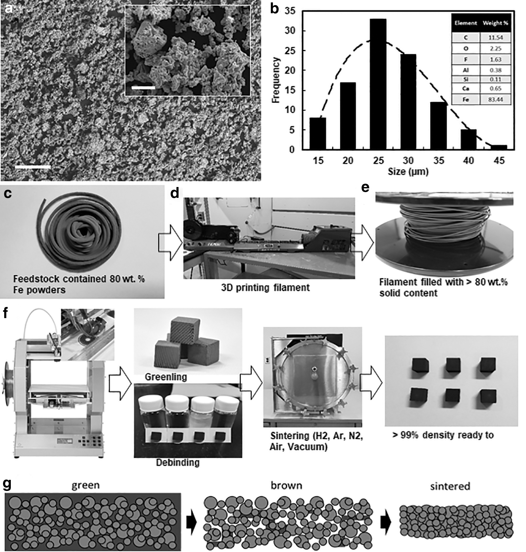
Water-dispersed hydrated, highly hydrophilic, Fe powder (purity >98%; Chemical Store, Inc.) was used as filler material for the developing of the filament (Fig. 1a). The Fe powder was a non-spherical flake-like material. The particle distribution was analyzed with scanning electron microscope (SEM) (CARL ZEISS EVO LS25). As depicted in Figure 1b, the values of D10, D50, and D90 of the Fe powders were around 15, 25, and 40 μm, respectively. The polymer binder components consist mainly of thermoplastic polyolefin as a backbone structure, and an elastomer, which were mixed in three different weight ratios of polyolefin/elastomer (1, 0.4, and 0.14) and flow additives and plasticizer, respectively, and surfactants in relation to the polyolefin and elastomer of 1.81 (F1), 2.95 (F2), and 5.62 (F3) were added for better processability of the hydrophilic, Fe powder and non-polar polymer binder. The surfactants (fatty acid–stearic acid) and additives were needed to promote also the homogeneity of the Fe powders in the polymer binder and the flow behavior and melt viscosity of the filament for better printability. The characteristics of Fe powder are listed in Table 1.
Characteristics of Fe Powders
Feedstock preparation
The explored filament feedstocks contained a fixed metal powder loading (80 wt.%) with respect to the varied polymer binder compositions, which were named as F1, F2, and F3. Before mixing the polyolefin and the elastomer, both materials were dehydrated in a conventional oven at 40°C for 1 h. The mixing process was conducted with two methods, on the one hand with a DSM mini-extruder (MICRO 15) and on the other hand with a twin-screw extruder rotating with 60 rpm at temperatures between 160°C and 180°C. The as-prepared feedstocks containing polymers and metal powders were finally pelletized and extruded into a filament with a diameter of 1.75 mm by using a single-screw extruder (Filabot).
The feedstock, the single-screw extruder, and the fabricated filament are shown in Figure 1c–e. The Fe filament was wound on a spool and printed finally with a FFF printer (Renkforce 1000) at 170–190°C (Fig. 1f). All our filaments could be bent with a bending radius <10 cm, which enabled safe handling and winding of the filament on the spool for printing.
Printing parameters
We evaluated the filament printability and the sintering performance by printing cubes of 1 × 1 × 1 cm. The cubes were printed with a 0.4-mm nozzle. The layer thickness was designated at 300 μm, and the fill pattern was a compact rectangle to achieve solid features. The printing temperature was 160–170°C, and the printing bed temperature was maintained at 60°C for better adhesion. The so-called greenlings cubes were debound in acetone/heptane and subsequently sintered. We evaluated the weight loss and volume shrinkage of the cubes during the whole process chain. The manufacturing process chain is depicted in Figure 1f.
Thermal and rheological characterization
The thermal decomposition temperatures of the polymer materials and the heating rates to be applied were determined by thermogravimetric analysis (TGA) (TA Instruments Q500) in N2 atmosphere, with a gas flow rate of 50 mL·min−1. The rheological properties of the feedstocks were characterized by ARES Rheometer (TA Instruments) at 160°C and 170°C, with shear rates ranging from 0.01 to 600 s−1 simulating the printing process.
Debinding, sintering, and material characterization
Solvent debinding was performed by soaking the green parts in an acetone-heptane (1:1) bath at 50°C and dehydrating it at 40°C for 2 h. Subsequently, the as-debound parts (brown part) were transferred to a muffle furnace for the thermal debinding process and sintering. The leftovers of polymer binder in the brown part were progressively removed by increasing the temperature, and the pure metallic Fe structure was obtained finally as a sintered part (Fig. 1g).
For all process steps, the debinding ratio and volume shrinkage were investigated in terms of weight loss and shrinkage.
The sintered materials were analyzed by using an X-ray diffraction analysis (XRD) (Rigaku smart lab), an optical microscope, and SEM/energy-dispersive X-ray spectroscopy (EDS) (Zeiss EVO LS25).
Results and Discussion
Binder removal by solvent debinding
For the feedstock preparation, additives and surfactants were used, to facilitate the printing and extrusion process, whereas the polyolefin and the elastomers served as a backbone to strengthen the green part and enable the preparation of the flexible filament. The elastomers were especially crucial to enable a high degree of filament flexibility, which is required for the printing and handling process. The two-step debinding and sintering process was designated to minimize the defects that might occur during the thermal treatment.
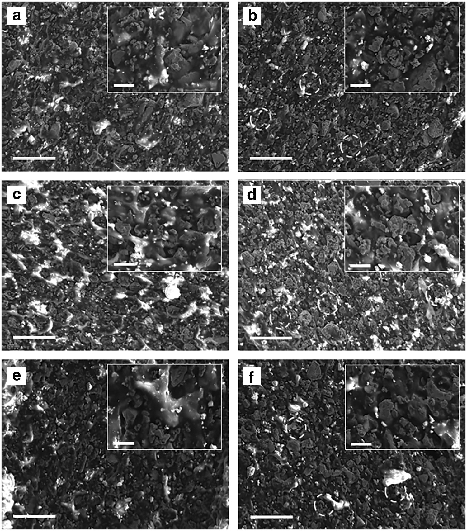
Figure 2 shows the SEM images of green parts before and after the solvent debinding. As can be seen, for all three feedstocks, channels in between the Fe flakes emerged across the surface. Those channels and pores gave two primary benefits. First, these channels and pores are working as pathways for gaseous binder components during the thermal debinding process and prevent bloating of the part. Second, the pathways also promoted a faster heating and decomposition, which reduced the time that was spent on the thermal debinding process. 27
SEM images of the green part before and after solvent debinding,
It was observed that the weight loss of the printed parts during the solvent debinding could rapidly reach up to 15 wt.% in the first 24 h, whereas a very slow change was obtained in the next 24 h, suggesting that 24 h is a suitable period for the solvent debinding process (Fig. 3a, b). The total polymer binder loss after 24-h solvent debinding was around 70 wt.% of binder.

Thermal analysis for thermal debinding and sintering process
To optimize the thermal debinding process, TGA in the temperatures ranging from 25°C to 600°C was performed in an N2 atmosphere. Figure 3c shows the TGA curves of the filaments. As can be seen, the first decomposition step occurs between 270°C and 350°C due to the loss of additives and surfactants. The second major decomposition step appears between 360°C and 430°C. It is worth noting that the polymer binder is completely decomposed at around 600°C.
The thermal debinding and holding temperatures for the manufacturing process were derived from the TGA curves and defined as depicted in Table 2. The holding time at each temperature varied from 20 to 60 min related to the amount of material and decomposition speed. Ultimately, the printed parts were sintered at 900°C.
Schedule of the Thermal Sintering Process
Rheology analysis
The rheological properties of the feedstocks were critical for the printing process. In this work, the rheological tests were conducted at the temperatures 160°C and 170°C. It is known that the polyolefin displayed a pseudoplastic behavior, as its viscosity decreased with increased shear rates. 28 The results in Figure 3d and e confirm pseudoplastic behavior of our feedstocks.
Higher viscosities were observed for feedstock F1 and F3 in comparison with feedstock F2. The elastomers could be mixed homogenously with the other polyolefins, supported by additives and surfactants, to reduce the overall viscosity. Based on the results, the proper elastomer ratio to get a high-quality filament ranges from 0.4 to 1. The utilized fatty acids as surfactants were used to improve the miscibility of the Fe powder with the polymer compound. The melt viscosity of the feedstock decreased with increasing temperature, and shear rates between 10 and 600 s−1 were found. That suggests that between 160°C and 170°C is a low viscosity during printing, which is desired for the process. 28 Hence, the filament F2 showed overall superior performance.
Debinding and sintering process
The thermal debinding and sintering process described in Table 2 contains multiple stages, which helped retaining the shape of the part and preventing inflation during the debinding. After the solvent debinding, first the part was heated up to 270°C to create more channels and pores throughout the structure by decomposition of a part of the binder. At this stage, the part became lighter and its volume had shrunk slightly (step 1 in Table 2). Subsequently, a lower heating rate was utilized with various holding times, to gradually remove the backbone materials (step 2–4 in Table 2). At the sintering stage, the part was treated with 900°C, resulting in an evident volume shrinkage (step 5 in Table 2). The weight loss and volume shrinkage of parts are shown in Figure 3f and g. The data points were collected at the status of the green parts, brown parts (after solvent debinding), and sintered parts.
As shown in Figure 3f and g, a highly complying trend was observed with the aforementioned part behavior. The weight loss was around 20% of the part, which was consistent to the initial content ratio between binder and Fe powder (Fig. 3f). The volume shrinkage of the sintered part reached up to 14%, in comparison to the green part (Fig. 3g).
Figure 4 shows the SEM images of sintered and polished surfaces and the corresponding EDS spectra. Apparently, the distinctive boundaries of Fe particles observed in the green and brown parts became vague after sintering, due to the particle consolidation. Further, the majority of the remaining polymeric residues were eliminated, due to the comparable Fe wt.% and carbon wt.% of the sintered part and the raw Fe powder (see Figs. 1b and 4c, f, i). By measuring the surface area of pores, in the polished 2D picture, it turned out that the area covers around 1–2% on the surface. That indicates that most of the channels and pores were eliminated. Benefiting from it, the part became denser. Fully dense parts are expected at higher sintering temperatures.

SEM images and EDS spectrum of parts after sintering and polishing
XRD analyses were performed for feedstocks (F1, F2, and F3) after printing (Fig. 5a), and after sintering (Fig. 5b). The measured peaks in Figure 5a can be assigned to the binder system and raw Fe powders. After the thermal debinding and sintering, only three peaks are in accordance with the original Fe peaks of the green part. The sintering process of the Fe powder has caused a phase change from a dominant pure Fe phase 29 to a mixture of Fe and Fe3C.29–31 We found peaks at 36°, around 46°, 61°, and 77° assigned to Fe3C after sintering.29,31 We could also show that the full width at half maximum of Fe peaks at 45° changed from 0.44 to 0.52, which implies that the crystallinity of the sintered Fe material increases by the sintering process.

XRD patterns of feedstocks in
Fabrication of desired metallic part
In FFF, the fabrication of a metallic part into a desired dimension is challenging due to the shrinkage of the printed parts during the sintering. The shrinkage in z direction is usually different from the one along the x and y directions in our study. We found that the directional shrinkage was subjected to the printer settings, such as, for example, layer height, extrusion temperature, infill percentage, amount of material extruded, etc. Different specimen shapes were printed by using various settings. The shrinkage ratio in each direction was recorded. As a result, two coefficients (fx-y and fz), one related to the x-y plane and the other one related to the z direction, were concluded to predict the dimensions of the sintered part, as the shrinkage was assumed as occurring linearly. Equations (1) and (2) depict the algorithm, where the dimensions of the sintered part could be estimated by multiplying the respective coefficients of those of the green part, whereas the coefficients (fx-y and fz) were estimated by the experimental records empirically and also related to printer settings.
where L′ is the side length on the sintered part, L is the side length on the green part, f is the coefficient, δ is the constant related to printer settings, n represents the number of printer settings that affect the green part (e.g., layer thickness and extrusion multiplier), x-y represents the x-y plane, and z stands for z direction.
Figure 5c shows the printed cubes at the stage of green-, brown-, and sintered parts. For the sintered specimen, fabricated by feedstock F1, fx-y and fz were, for example, 0.946 ± 0.006 and 0.954 ± 0.004. Note that the algorithm is highly dependent on the filament loading and printer settings. Figure 5d shows the printed prototypes and the investigated Fe ring in the middle, printed by the F2 filament and designed by the developed model to manufacture accurate parts dimensions.
Experimental magnetic characterization
A ring core experimental test bench provides DC and AC magnetic characteristics of the FFF rings. The relationship between the magnetic induction, B(t), and the magnetic field intensity, H(t), was determined by applying Faraday's and Ampere's circuital law to the closed magnetic circuit. Evenly distributed primary and secondary copper windings wound around the ring help generate a uniform distribution of the flux.
Here,
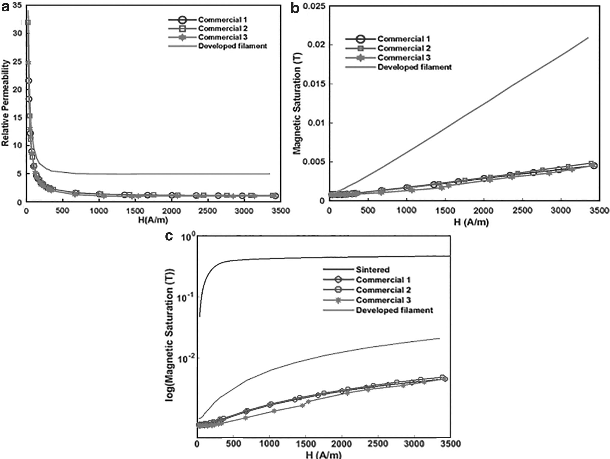
High magnetic permeability at low field strength and high magnetic saturation are two of the many desired magnetic properties for the magnetic core of electric motors. Although quite low for use in electrical motors, the newly developed iron filaments have higher magnetic permeability and magnetic induction than commercially available iron filaments, shown in Figure 6a and b. The powder content of commercially available iron filaments is usually significantly lower <20 vol.%. Hence, our developed filaments outperformed the commercial material.
Comparison of
As shown in Figure 6c, the magnetic permeability of the developed filament significantly improves after sintering. The flux density at 500 A/m is nearly 40 × higher than its value before sintering. Magnetic saturation of the sintered part is about 0.5 T, as shown in Figure 6c.
Conclusions
We developed three FFF filaments with 80 wt.% incorporate Fe powder. The investigations on the solubility and thermal properties of the polymer-binder were conducted to optimize the two-step debinding and sintering processes. The rheological analysis performed on filament feedstocks revealed the potential effect of each binder component on the viscosity. An algorithm was developed to predict the shrinkage of sintered parts. Ultimately, Fe core prototypes (rings) were printed and sintered and their magnetic properties were evaluated.
We believe that the developed Fe filament, which has reliable mechanical properties and excellent performance toward part fabrication, will be interesting for further applications in the field of electric motors or related applications.
Footnotes
Acknowledgments
The authors thank Dr. Mike Rich, Dr. Brian Rook, and Dr. Per Askeland in Michigan State University for their helps in this work. They would also like to acknowledge the three ECE undergraduate students who assisted with the magnetic characterization: Ms. Tia Smith, Ms. Lauren Kaliszewski, and Mr. Joshua Ward.
Author Disclosure Statement
No competing financial interests exist.
Funding Information
Internal funding, no public sources.