
Abstract
The selective laser melting (SLM) process of the Cu-10Sn alloy and effects of heat treatment were examined in this study. The Taguchi test and Box–Behnken design were performed to determine the laser power (LP), scanning speed (SS), and hatch space (HS). The best process parameters were selected using the highest density: the optimum HS was 160 μm; SS was 278 mm s−1; LP was 192 W; and density reached 98.76%. The tensile strength, elongation, Vickers hardness, and impact toughness of the Cu-10Sn alloy formed by SLM are 435 MPa, 13%, 122HV1, and 10 J·cm−2, respectively. Heat treatment can significantly increase the ductility and impact toughness of the Cu-10Sn alloy, but at the same time, it can reduce its strength. The strength of parts obtained by all five heat treatment methods is much greater than that of castings. Parts that are annealed at 600°C for 4 h have the best mechanical properties, its tensile strength and elongation were 378 MPa and 15%, respectively.
Introduction
Cu-Sn alloy, also known as tin bronze, has high mechanical properties, wear resistance and corrosion resistance, low shrinkage coefficient, and nonmagnetism and is mainly used in oil bearings, turbines, gears, springs, ship propulsion systems, and seawater treatment systems, etc. 1
Tin bronze parts are generally cast in three steps 2 : melting and casting process, hot working, and cold working. During solidification, tin bronze is prone to segregation and generates dendrites, forming discrete cavity shrinkage and crack growth, resulting in parts with low volume shrinkage and low density.3,4 These defects have a greater impact on parts with complex shapes. Many scholars used selective laser sintering (SLS) technology to manufacture copper alloy parts and obtained products with better mechanical properties.5–12 However, the SLS technology cannot completely melt the copper powder, so it is difficult to obtain high-density Cu-Sn alloy parts by SLS.
Selective laser melting (SLM) technology is an excellent additive manufacturing technology developed from SLS technology, which can solve these problems. 13 With SLM, complex parts are produced layer by layer with the use of high-energy, laser beam melting alloy powders based on computer-aided design models. In the SLM process, high-power density laser will heat and cool tin bronze parts in a short time. This rapid solidification process greatly reduces segregation and refines grains, thereby improving the mechanical properties and density of the parts. 14 Moreover, SLM technology has high precision (about 0.1 mm) and does not require molds, which are especially suitable for manufacturing complex or personalized medical parts.15–19 However, thermal residual stress, spherical effect, and microstructure heterogeneity usually greatly limit the performance of SLM products. To control the effects of these problems, the most widely used strategy is to change the SLM processing parameters and heat treatment methods. Wu et al. 20 used the scanning strategy of two scans with crossed scanning directions to increase the density of the SLM Cu alloy to 95%. Gustmann et al. 21 compared the density and performance of Al-Cu shape memory alloys obtained by different SLM process parameters.
In recent years, some researches on the manufacture of Cu-Sn alloy samples by SLM technology have been reported. Scudino et al. 1 verified the feasibility of forming the Cu-Sn alloy by SLM technology from the aspects of powder preparation, process parameters, microstructure and mechanical properties, and heat treatment. Ventura et al. 22 reported the electrical conductivity of the Cu-4.3Sn alloy formed by SLM. Kim et al. 23 studied the effect of heat treatment on the microstructure, mechanical properties, and thermal properties of the Cu-Ni-Sn alloy produced by SLM. Gan et al. 24 reported the forming process and mechanical properties of Cu-Sn-Ti/diamond composites fabricated by SLM. Mao et al. 25 obtained Cu-15Sn SLM specimens with high density (99.8%) and good mechanical properties. Tan et al. 26 reported the Cu-10Sn alloy with a body-centered cubic (bcc) lattice structure fabricated by SLM, and the different cooling rates of rods and nodes in the parts exhibited various grain morphologies and hardness levels.
The Cu-Sn alloy manufactured by SLM has good strength, but poor toughness, which limits its application. Heat treatment can greatly improve the toughness of the alloy while maintaining good strength. Changing the Sn content or heat treatment can significantly change the mechanical properties of Cu-Sn parts. In this article, the process parameters and performance of a high-mass density Cu-10Sn alloy were investigated and the effects of various heat treatment methods on the mechanical properties were studied.
Experiment
Experimental equipment and materials
The SLM equipment used in the experiment was Riton Dimetal-120, including an IPG fiber laser (λ = 1064 nm; maximum power, 500 W; and spot diameter, 70 μm). During SLM processing, the O2 concentration in the atmosphere was kept below 200 ppm using a positive pressure of N2 gas.
The Cu-10Sn used is commercial tin bronze powder (Sn content approaching 10%), which was prepared by gas atomization. The chemical composition of the tin bronze powder is listed in Table 1. The powder's appearance and particle size distribution, shown in Figure 1, had a high degree of sphericity to ensure that the laying powder was flat. The apparent density and theoretical density were 5.23 and 5.79 g/cm3, respectively.
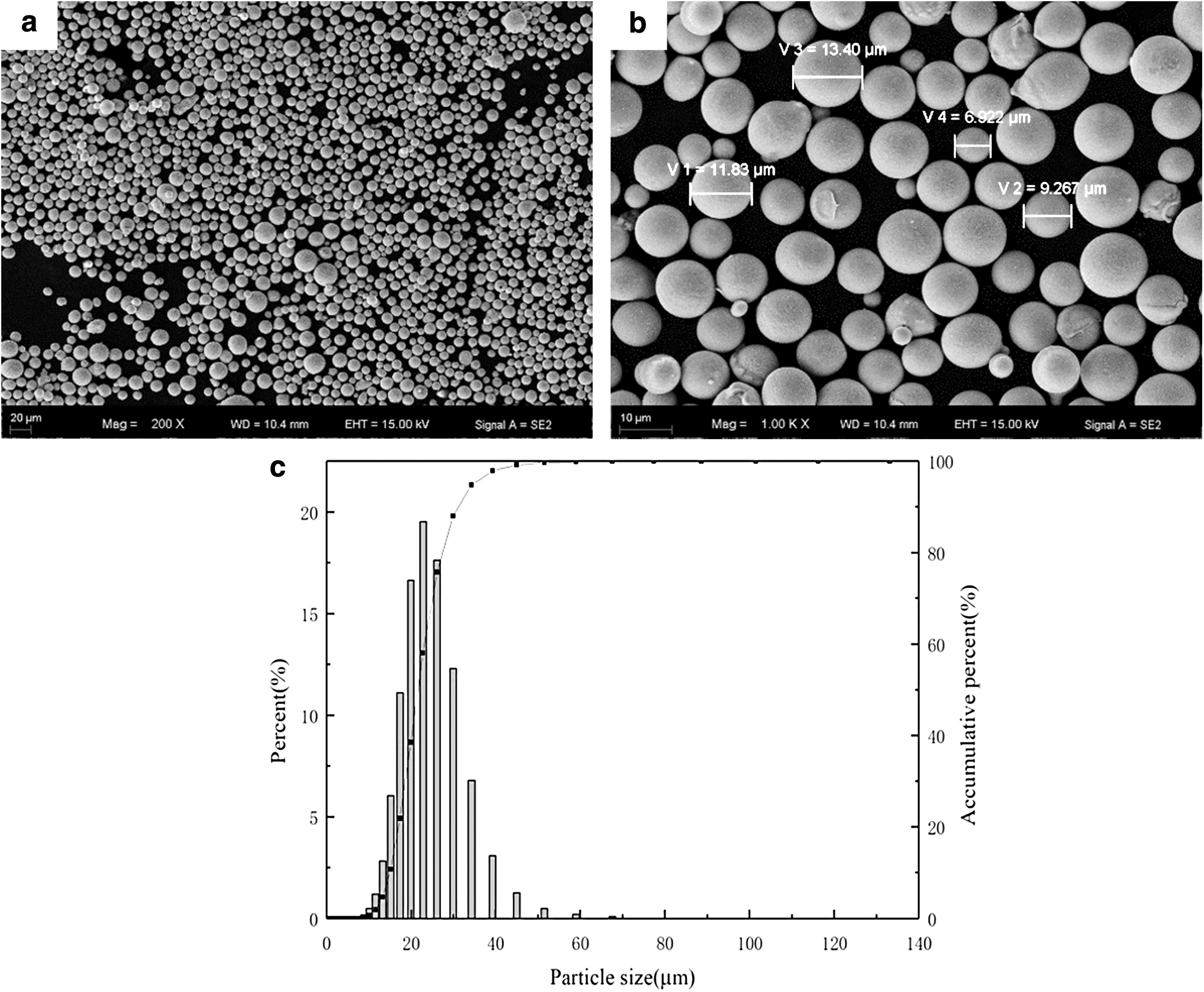
Cu-10Sn alloy powder microscopic morphology
Powder Composition of Cu-10Sn Alloy (wt. %)
Experimental method
SLM process optimization
In this article, 10 × 10 × 10-mm Cu-Sn alloy parts were formed with the SLM equipment and their relative density values were tested according to the Archimedean method, using a weighing accuracy of 0.1 mg on a JJ324BC electronic balance. The relative density can be calculated by the Archimedean method formula for relative density:
where ρ is the relative density;
In general, a lesser powder layer thickness can increase the density of SLM parts, but reducing the layer thickness will significantly increase the processing time. According to previous studies, a powder layer thickness of 30 μm and an S-shaped, orthogonal layer cross-scanning strategy were selected (shown in Fig. 2).

S-shaped, orthogonal layer cross-scanning strategy
The laser power (LP), scanning speed (SS), and hatch space (HS) of the three factors and five levels of the Taguchi test were designed, as shown in Table 2. Moreover, a response surface experiment was designed based on the Taguchi experiment. On this basis, with density as the response value, the SS (100, 200, and 300 mm·s−1), LP (150, 180, and 210 W), and HS (60, 90, and 120 μm) were selected as the three factors and three levels of the Box–Behnken design, as shown in Table 3.
Taguchi Test and Its Result for Three Factors and Five Levels
LP, laser power; HS, hatch space; SS, scanning speed.
Box–Behnken Design and Its Result for Three Factors and Three Levels
Heat treatment and microstructure observation
The heat treatment process used to study the effects of various solution-aging temperatures and cooling modes on the performance of SLM-molded parts is shown in Table 4.
Heat Treatment Process of Co-Cr Alloy
AC, air cooling; FC, furnace cooling; SLM-AS, selective laser melting-as-sintered; WC, water cooling.
The microstructure samples were fabricated with the optimized process parameters and etched by a corrosive agent (200 g of CrO3, 17 mL–35% HCl, and 20 g of Na2S2O3 in 1000 mL of H2O) about 2 min after grinding and polishing.
The morphology of the original and heat-treated samples was observed with an optical microscope (OLYMPUS BX53M) and a scanning electron microscope (Zeiss Supra 55VP). Phase analysis was performed with an X-ray diffractometer (XRD; BRUKER D8 ADVANCE) with CuKα.
Mechanical properties
The Vickers hardness test was performed with a Vickers hardness tester (DHV-1000Z-CCD), with a load of 1.0 kgf (9.8N) and a loading time of 15 s. Each sample was effectively measured three times, and the average value was taken as the result. The tensile test was carried out on a universal testing machine at 25°C with a displacement rate of 0.5 mm/min. The ultimate tensile strength was obtained from the stress–strain curve. A pendulum impact machine (ZRZ1452) was used to conduct an impact toughness test using the V-type Charpy impact test. The sample sizes and test methods used in this article were from ISO 6892-1:2009 (tensile test) and ISO 148-1:2006 (impact test).
Results and Discussion
SLM process
In this study, the laser spot diameter was about 70 μm. The strategy included S-shaped orthogonal layer cross-scanning and a fixed layer thickness of 30 μm. The model is thus defined as follows
27
:
where Ψ is the energy input density; LP is the laser power; r is the radius of the laser beam; SS is the scanning speed; and HS is the hatch space.
Taguchi test and its result
From the Taguchi test in Table 2, the optimum process parameters were an 80-μm HS, 200-mm·s−1 SS, and 165-W LP (No. 18). Variance of the relative density was analyzed, and the p-value (P) was used to judge the significance of the three factors; p < 0.05 indicates that the factor is significant and p < 0.01 indicates that the factor is highly significant. As shown in Figure 3, the SS has a small effect on density (p = 0.834). This may be due to the high thermal conductivity of the Cu-Sn alloy. With appropriate processing parameters, the laser energy will be quickly transferred to the nearby layer, causing the previous layer to be remelted, thus improving the surface quality of the previous layer.
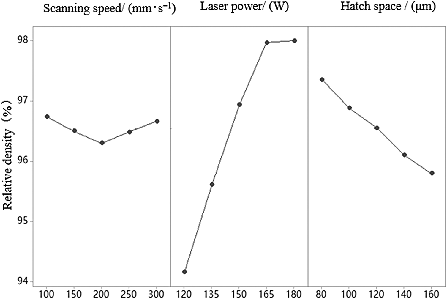
The main effect of density in the Taguchi relative test.
LP (p < 0.001) has the most significant effect on the density of parts among the three factors. When the LP is less than 160 W, the density increased as the LP increased. According to Equation (2), the increase in LP leads to a corresponding increase in the energy input density, so the amount of melting powder also increases. Under the action of surface tension and capillary force, the overlap between the melting trace is more compact and uniform, so the density will increase. When the LP is greater than 165 W, the LP will continue to increase, but the density increase is very less, which may be due to the formation of a powder-free zone near the melting trace.
The HS (p = 0.003) directly affects the overlap rate between the melting traces. As the HS increases, the overlap ratio decreases. If the HS is too large, the melting traces cannot completely overlap, which forms an insufficiently melted area, resulting in voids and reduced density.
Box–Behnken design and its result
In Table 3, the density of all SLM parts is greater than 97.5%, which basically meets the requirements of industrial applications. By calculating all the data in Table 3, we can get regression equations of the response value relative density (ρ) and the independent variables LP, SS, and HS:
Figure 4 shows the density response surface of SLM parts, and retention values are HS = 90 μm (Fig. 4a), SS = 200 mm·s−1 (Fig. 4b), and LP = 180 W (Fig. 4c). In addition, it can be seen that the influence of each of the three factors on the density of SLM parts is related to the other two factors, which must be considered comprehensively. On this basis, according to Equation (3), the maximum density in the Box–Behnken design range (60–160 μm, 100–500 mm·s−1, and 120–300 W) is 98.99%, and the corresponding HS, SS, and LP values are 159.99 m, 277.68 mm·s−1, and 191.62 W, respectively. Furthermore, the approximate values of 160 μm, 278 mm·s−1, and 192 W were selected to form three 10 × 10 × 10-mm square parts for verification. Their average density was 98.76%, which was very close to the calculated maximum value obtained above.
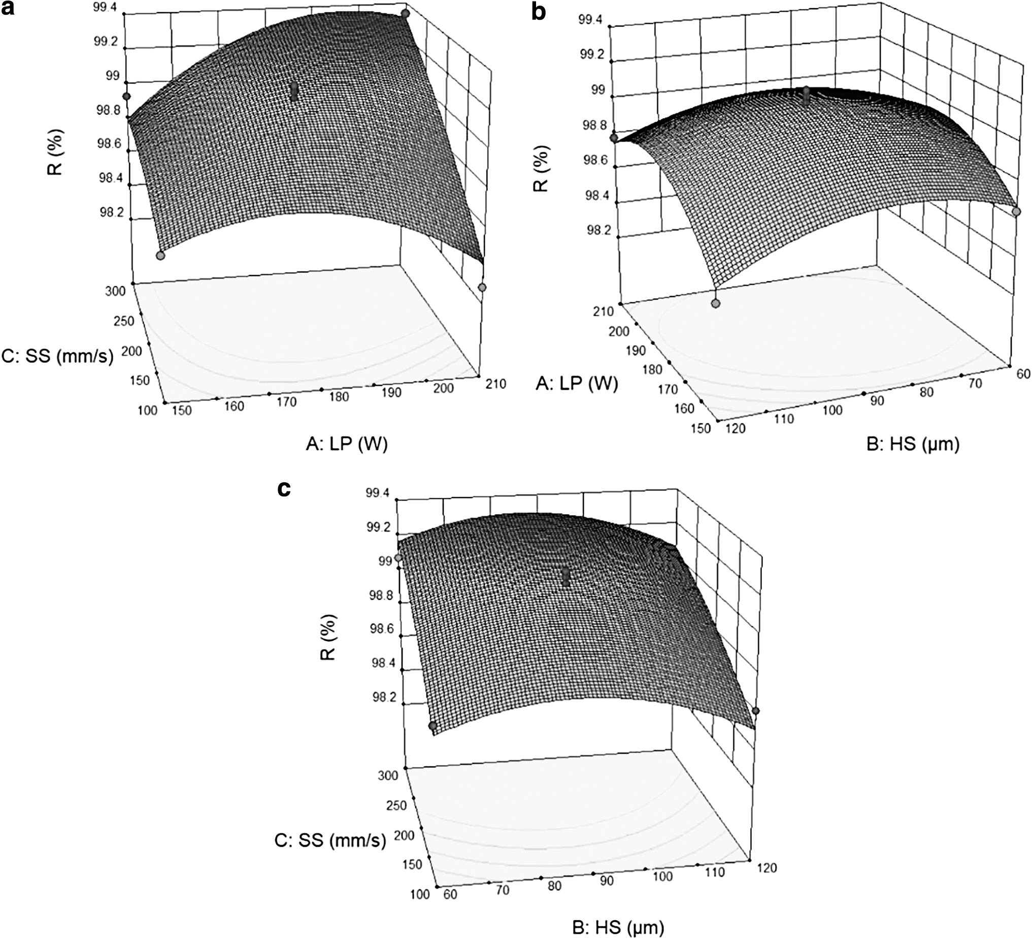
Response surface of relative density
XRD phase analysis
XRD measurements of the Cu-Sn alloy powder and the original sample and various heat treatment samples (Table 4) were performed as shown in Figure 5. The α-Cu phase face center cubic (fcc) is a solid solution in which Sn is solid-dissolved in the Cu matrix and has good plasticity. The δ (Cu41Sn11) phase (fcc) is generally between the dendrite a-Cu phases, which is a hard and brittle phase. The metastable β′ phase body centered cubic (bcc) is generated by displacive transformation and has good high-temperature plasticity.

X-ray diffractometer patterns of the Cu-10Sn alloy powder, as-sintered and heat-treated parts.
Compared with Cu-10Sn powder, the β′ phase of SLM parts increased significantly and the δ phase decreased. This is because in the SLM process, cooling is rapid, so some Sn atoms in the β phase cannot diffuse into the a-Cu phase, which allows the metastable β′ phase to be retained.
As the annealing temperature increases, the β′ phase and δ phase in the SLM part decompose successively. At 300°C, as shown in Figure 5c, the metastable β′ phase decomposes and transforms into the α phase, and the hard and brittle δ phase plays a strengthening role in the structure. At 400°C, as shown in Figure 5d, the δ phase also begins to decompose, and the structure almost entirely comprises the α phase. At 600°C and 800°C, as shown in Figure 5d–f, the peak of the α phase becomes sharper, indicating that the grains in the structure are becoming larger.
Microstructure analysis
The Cu-10Sn parts manufactured by SLM were heat treated in different ways (Table 4) and their metallographic diagrams are shown in Figure 6. As shown in Figure 6a–c, in the unannealed or low-temperature (300°C and 400°C) annealed parts, almost all of them contain fine cellular grains, and the grain size increases with the increase of annealing temperature. These cellular grains may be the transverse section view of columnar grains. 26 As shown in Figure 6d, the grain size becomes significantly larger, and the recrystallization grain and twins can be observed in the metallographic structure annealed at 600°C. The occurrence of twins indicates that part of the stacking fault disappears and the internal stress is relieved, which reduces the strength and enhances plasticity. Compared with Figure 6d, the size and number of twins in Figure 6e and f increase, and the grains become larger and the structure becomes more uniform. The plasticity of the alloy is further enhanced and the strength is further reduced.
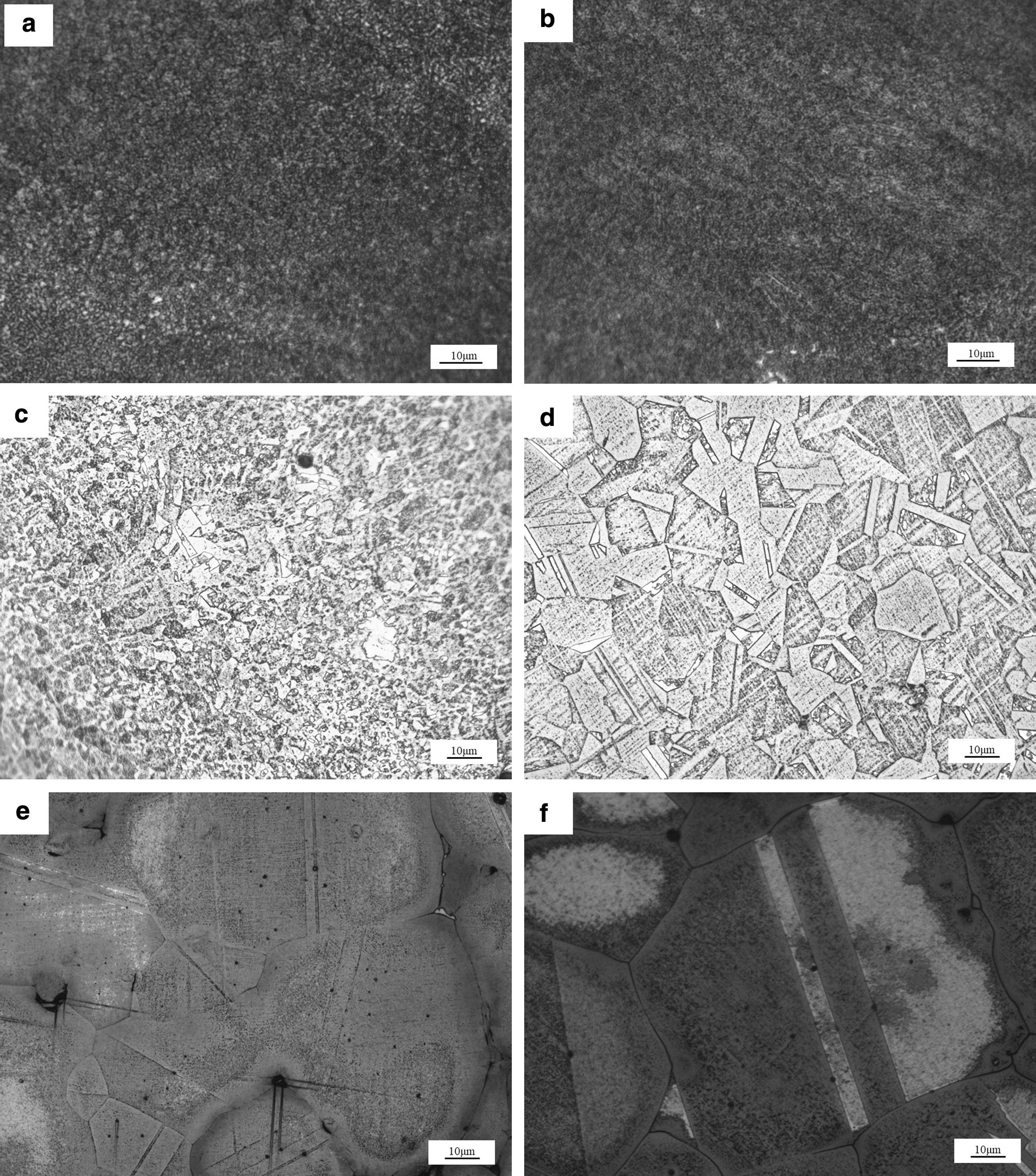
Metallographic diagram of SLM parts with different annealing methods:
Mechanical property analysis
Figure 7 shows the breaking strength, yield strength, elongation (ɛ), impact toughness, and Vickers hardness of as-sintered and heat-treated parts. As shown in Figure 7a and b, the parts annealed at 300°C have a maximum tensile strength of 489 MPa and a yield strength of 357 MPa and the minimum at 800°C. The tensile strength of all parts is greater than 340 MPa, which is significantly increased compared with 180 MPa of cast parts. 1 At 300°C, the β′ phase decomposes and decreases, while the hard and brittle δ phase increases, enhancing the tensile properties of the part and reducing its elongation. At 400°C, the δ phase begins to decompose into the α phase, the yield strength and tensile strength of the part decrease, and elongation increases. At 600°C and 800°C, the δ phase has been completely decomposed into the α phase, and the increase in temperature will increase the grain size, the plasticity of the part will further increase, and strength will continue to decrease. The application of water cooling in the 800/400 group accelerates the cooling rate and suppresses the growth of grains. Therefore, compared with 800°C, it has greater strength and lower elongation. Figure 8a shows the room-temperature tensile fracture morphology of SLM-as-sintered (SLM-AS) parts. A large number of tearing ridges and some small dimple-like structures can be seen, which are mixed fractures.

Mechanical properties of as-sintered and heat-treated parts:
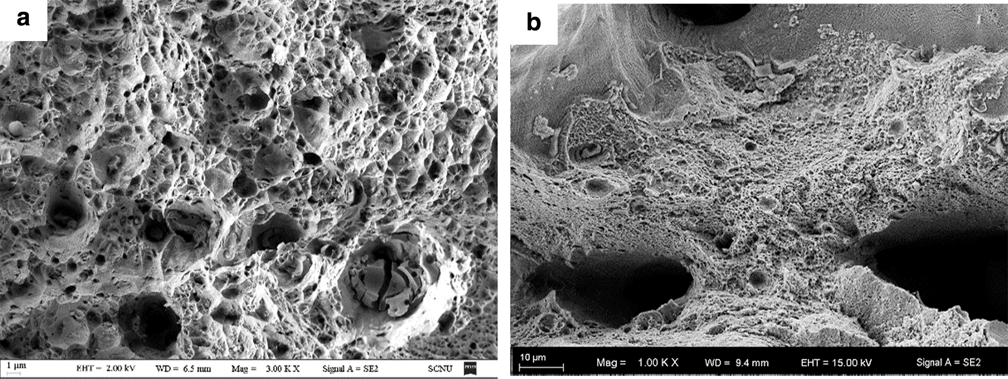
Fracture patterns of SLM-AS:
As shown in Figure 7c, the impact toughness first decreases as the annealing temperature increases, then it increases. SLM-AS parts and parts annealed at 300°C have lower impact toughness values and exhibit brittleness. However, the parts annealed above 400°C have a larger impact toughness value and show relatively good toughness. This is because the increase of annealing temperature converts the hard and brittle δ phase into the plastic α phase. Figure 8b shows the room-temperature impact fracture morphology of SLM-AS parts, which includes lots of tearing ridges, small dimple-like structures, and river patterns, so it is classified as cleavage fracture.
As shown in Figure 7d, the hardness of 300°C annealed parts is much greater than that of SLM-AS. This is because the low-temperature annealing decomposes the β′ phase in the SLM-AS part, thereby increasing the δ phase. As the annealing temperature increases, the δ phase decreases, grain size becomes larger, and hardness decreases. In the 800/400 group, water cooling suppresses grain growth, so its hardness is higher than that at 800°C.
Conclusions
In this study, Cu-10Sn alloy parts were formed with SLM. The forming process and properties of Cu-10Sn alloy were analyzed, and the results of five heat treatments were compared. The following conclusions were obtained:
The optimum process parameters were obtained by Box–Behnken design. The optimum HS is 160 μm; SS is 278 mm·s−1; LP is 192 W; and relative density can reach 98.76%. After heat treatment, the structure of Cu-10Sn alloy parts is mainly composed of the α phase. As the annealing temperature increases, the metastable β′ phase and the hard and brittle δ phase successively decompose into the α phase, and Sn atoms diffuse into the α phase. The tensile strength, elongation, Vickers hardness, and impact toughness values of the original Cu-10Sn alloy formed by SLM are 435 MPa, 13%, 122HV1, and 10 J·cm−2, respectively. The room-temperature tensile fracture mechanism of the specimen is mixed fractures, and the room-temperature impact fracture mechanism of the specimen is cleavage fracture. The best heat treatment process is 600°C × 4 h and its tensile strength and elongation are 378 MPa and 15%, respectively.
Footnotes
Author Disclosure Statement
No competing financial interests exist.
Funding Information
This work was financially supported by the National Key Research and Development Program of China (2017YFB1104500); Department of Science and Technology of Guangdong Province (2018B030323017, 2018KQNCX057); Key Area Research and Development Program of Guangdong Province (2020B090922006); Young Innovative Talents Project in Universities of Guangdong Province (2018KQNCX057); Young Scholar Foundation of South China Normal University (19KJ13); and Featured Innovation Project of the Guangdong Education Department (2019KTSCX034).