
Abstract
Layered assembly is a voxel-based additive manufacturing process that relies on parallel grasping of voxels to produce multi-material parts. Although there exists substantial diversity in mechanisms of gripping, there still exists a lack of consistency, accuracy, and efficacy in positioning very large numbers of milli-, micro-, and nano-scale objects. We demonstrate the use of parallel electro-osmotic grippers to selectively transport multiple millimeter-sized voxels simultaneously. In contrast to previous research focused on using arrays of droplets to grab a single substrate, each element in the array is individually controlled via capillary effects, which are, in turn, controlled by an electric field to create predetermined patterns of droplets to pick and place selected objects. The demonstrated fluidic pick-and-place method has two key advantages: It is suitable for transport of fragile and complex objects due to the lack of mechanical contact, and it easily parallelizes to arbitrary array sizes for massively parallel pick-and-place. This work demonstrates a 25-element parallel assembly of 1.5-mm spheres with 95–98% grasping reliability, in a variety of geometric patterns. Experimental performance was validated against both analytical and computational models. The results suggest that electro-osmotic droplet arrays may enable the additive manufacturing of multi-material objects containing millions of components in the same print bed.
Introduction
Present-day additive manufacturing
Established additive manufacturing processes struggle to co-fabricate parts comprising dissimilar materials in the same build chamber. Although some of the most sophisticated additive manufacturing processes can manufacture launch-rated metal parts, or high-energy laser mirrors, 1 they are unable to manufacture simple electromechanical devices such as flashlights. Previous works in multi-material fabrication include attempts to perform additive manufacture of batteries, 2 or the direct writing conductive inks on flexible substrates. 3 These approaches continue to have incremental success, however they remain bottlenecked by two fundamental limitations. First, material properties are often compromised to achieve compatibility of dissimilar materials inside the printer. Second, the resolution of additive manufacturing processes eliminates the possibility of manufacturing precision features such as fine pitch circuit features. 4 As a result of these issues, a significant research gap exists in the digital manufacturing of electro-mechanical parts.
One way to address this research gap is to preassemble electro-mechanical parts from small bits of dissimilar materials so that material property incompatibility is solved outside the printer rather in the print chamber. To produce high-resolution parts, such a manufacturing process would require the assembly of large numbers of miniature components, the number of which grows exponentially as product complexity increases. The present-day bottleneck in massively parallel assembly is the ability to assemble components comprising dissimilar materials in parallel. Although present-day pick-and-place robots can assemble sub-mm units at rapid rates of several parts per second, 5 these rates do not effectively scale to objects with high component counts. To alleviate this manufacturing bottleneck, we explore the notion of massively parallel pick-and-place processes, with a technique that we call Layered Assembly (LA). 4
Layered Assembly
Instead of assembling multiple components serially 6 in rapid succession, LA can simultaneously position large numbers of components of a given layer. The proposed parallel droplet array then picks up only selected components in the chosen predetermined configuration and places them onto the build plate. The components are released in intended positions by reversing droplet formation, thereby reducing the electro-osmotic gripping force. Once disparate components are positioned, they can be secured in place immediately, or in a postprocessing step. The specific means of joining adjacent objects can vary depending on the object functionality, material properties, and desired properties of the composite assembly. Components with interlocking features could be secured by press fits, conductive objects could be secured by prewicked solder, 7 and polymers can be adhered together by acrylic sprays. 4 Ultimately, the component assembly rate scales with the number of component types and layers, rather than with the number of individual components, making parallel LA order-of-magnitude faster than traditional serial pick-and-place methods.
There are three main issues to consider when selecting a transport mechanism for an mm-sized object using traditional grasping methods. First, the end effector must match either the entire or part of the object shape and must grasp the object without damaging it. Second, most devices currently designed to pick up small objects are typically extremely fragile, often as fragile as the objects they are trying to pick up, limiting the speed of grasping. Finally, repeatability of the picking motion is essential for large-scale operations. The repeatability and reliability of the end effector can be increased by using parallel pick-and-place operations.
Common end effectors for small-scale pick-and-place processes include pipette vacuums, 8 nano- or micro-fabricated tweezers 9–11 attached to parallelogram arms, 12 and electrostatic grippers. Other approaches use scanning electron microscopy and atomic force microscopy to move small objects.13,14 These techniques are difficult to parallelize and lack a universal end effector for picking up diverse geometries. Another technique is continguitive gripping, 15 which involves the use of chemically activated micro-grippers. Although this technique requires low energy input, the submersion of materials into chemicals can degrade and deform components. 16 Self-alignment via capillary bridges has been previously used to align tiles, removing some of the precision boundaries in assembly.17–19 Often referred to as heterogenous assembly, or digital materials, capillary gripping has shown promise as an actuation-free, solid-state method of manipulating micro-objects.20,21
Electro-osmosis for parallel grasping
In this work, electro-osmosis is used to create droplets to selectively pick-and-place mm-scale objects, predetermined by use of the parallel and individually controlled electro-osmosis mechanism (PICEM). Once an object is picked up by the PICEM, polarity is reversed, decreasing the capillary bridge volume. The constant-volume instabilities of a liquid bridge pinned on a plate at one end and a sphere at the other end are well characterized and understood. 22
The long-term goal of this work is to develop a solid-state parallel gripping device that is capable of assembling millions of arbitrary objects in parallel and in a predetermined configuration. Assembly precision can be enhanced by unique self-alignment properties that are inherent from capillary. In this work, we restrict ourselves to focusing on the statistics concerning the repeatability of picking up a predetermined configuration and characterization of the droplet exit velocity. Results from a simple analytical model capturing the essential physics of the fluid motion through the device accompanied by simulations of the flow field for visualization are compared with an experimentally measured global average velocity for both a thick and thin Debye layer.
Materials and Methods
PICEM device overview
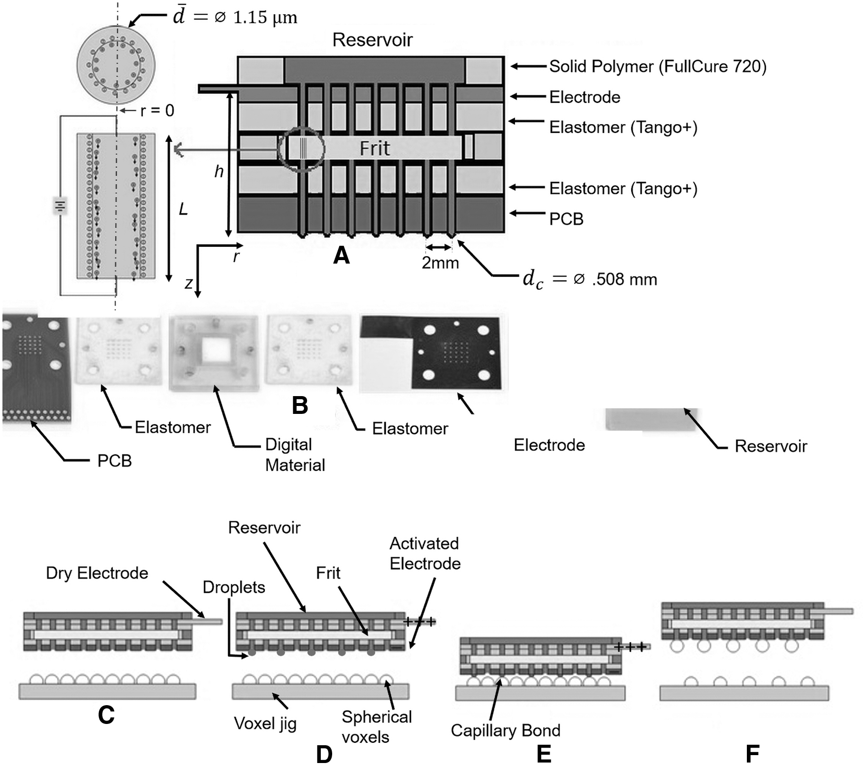
The PICEM was inspired by the switchable electronically controlled capillary adhesion device (SECAD) shown in Figure 1, and in Supplementary Movie S1. The SECAD uses electro-osmosis to move an array of droplets that form capillary bridges on contact with a single substrate (e.g., a piece of aluminum foil) or an array of objects.23,24
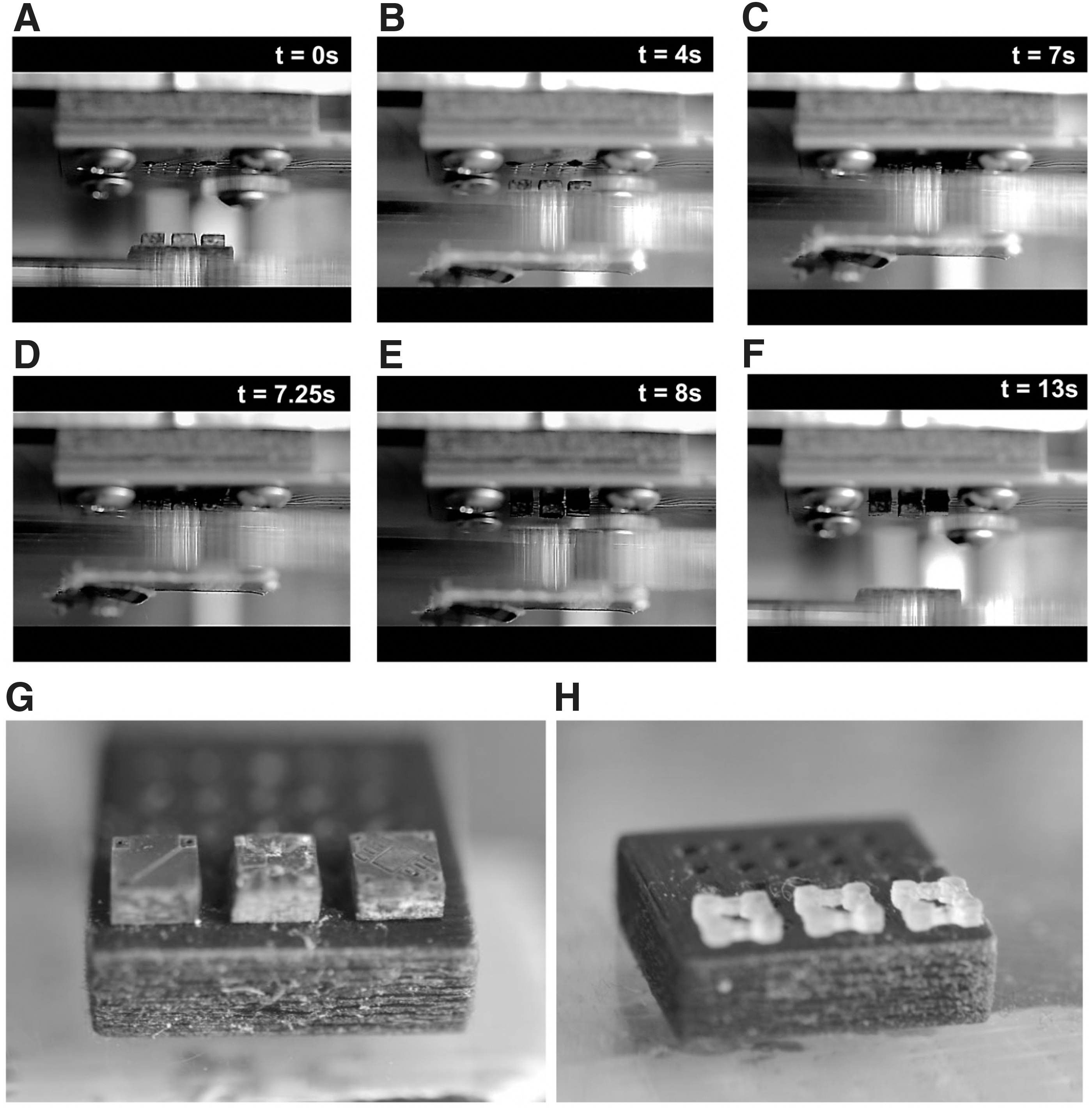
The key difference between the PICEM and the SECAD is that the PICEM can individually control channels to selectively pick-and-place small objects arranged in arbitrary configurations, obviating hardware such as micro-fabricated tweezers. Another benefit is the self-alignment of objects from the capillary bridges seeking the lowest energy state, as seen in Supplementary Movie S2. The main steps of this parallel electro-osmotic grasping process are shown in Figure 2C–F.
Parallel pick-and-place process:
When a solid and a liquid come into contact, the surface groups of the solid are removed, leaving behind a layer of charge. Counter-ions from the bulk fluid migrate to the liquid–solid interface to neutralize the excess charge, creating an electric double layer. When a tangential electric field is applied, the ions in the diffuse layer respond to Coulombic forces and move toward the electrode of opposite polarity. As a result of viscosity, the surrounding bulk fluid is convected, creating a bulk flow. 26 This phenomenon allows for fluid motion without any mechanical devices that are necessary to control a constant, pulse-free fluid flow. If a porous frit is used as the solid, a considerable pressure drop occurs across the frit. This must be taken into consideration when looking at bulk fluid flow through the medium.
PICEM assembly
The PICEM mostly comprises three-dimensional (3D)-printed components (Fig. 2A, B) of varying durometers fabricated on a Stratasys Connex 500 3D Printer. Besides the electrodes, printed circuit board (PCB), O-ring, and connectors, all layers were created using photo-acrylates of varying durometers. The screws and the top plate keep water in the intended channels and are made up of a low durometer material (Shore A 27), which allows for a rubber-like flexibility (Fig. 2A).
27
The borosilicate glass frit, equipped with 1.15
Individual control and component details
The printed circuit board has a 5 × 5 array of 508 μm diameter holes with a 0.66 mm diameter Sn/Pb plating. The center-to-center distance between adjacent channels was 2 mm. This spacing was chosen to better analyze the effects of the generated electric field in adjacent inactivated channels. An XYZ gantry platform was built for motion control of the PICEM, allowing it to pick-and-place tiles or spheres from any location on the platform. The objects grasped in this article consisted of 1.5 mm diameter spheres, interlocking bricks, and mm-scale circuit components, as summarized in Table 1.
Components from Figure 6, and Their Respective Material Properties
Analytical solution
Among the various models available
28
for modeling fluid flow through porous media, we have chosen to follow the basic framework set forth by Kirby.
29
Use of a modified form of the electro-kinetic coupling matrix to calculate the droplet exit velocity requires that the flow is unidirectional, and that the electrochemical equilibrium of the ions in the double layer is decoupled from the bulk flow. For the latter to be satisfied,
The exact form of the modified electro-kinetic coupling matrix is dictated by the ratio of the average pore diameter to the Debye length,

where
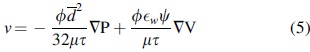
The net axial velocity of fluid through the frit as a result of an externally applied electric field is a superposition of the Helmholtz-Smoluchowski electro-osmotic velocity and Darcy's law modified with the appropriate coefficients to account for the finite thickness of the double layer 29 :
where
Assuming that the double-layer thickness does not affect the viscosity, the functional dependence of the second term on the right-hand side remains the same as that for thin double layers (i.e.,
This numerical approximation is accurate to within 10% if the condition on the dimensionless surface potential,
The simplest expression for the electric field is
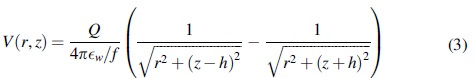
where
The electric field in the axial direction is the gradient of the potential field with respect to z. Or,
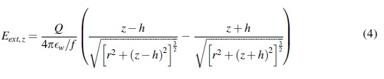
Using the value for Q calculated with Equation 3, the electric field at the coordinates specified above is 7079 V/m. From here, the velocity at the frit exit can be determined by Equation 2. Assuming that the velocity profile is well developed along the rest of the flow path above the frit, we can approximate the centerline velocity at the exit of a single activated channel to be the same as that at the frit exit, 0.12 mm/s (thick DL). This equation can also be used to find the effects of an activated channel's electric field on other neighboring channels by varying r.
The analytical solution treats the electric field as that between a point charge and an infinite plate. In reality, it is not a point charge, but a thin ring of Sn/Pb coating around the channel, and the plate is not infinite. For our experimental setup, this treatment is appropriate because a quick scaling analysis reveals that the ratio of the channel diameter to the distance between the channel inlet and the plate electrode is small (
Simulations
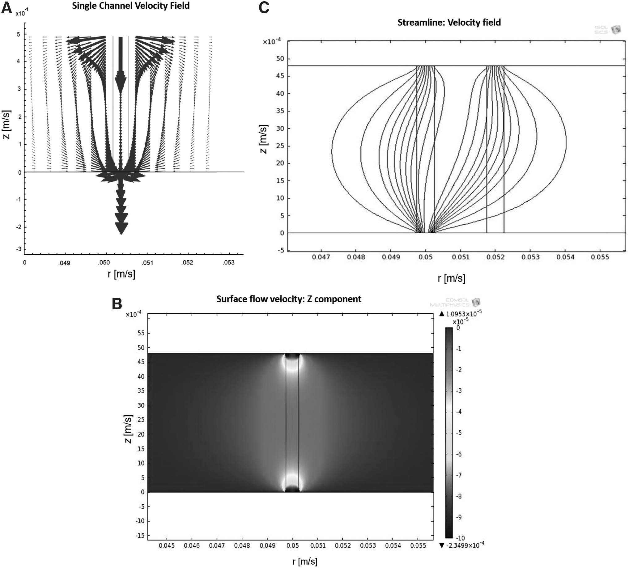
COMSOL Multiphysics (Model ID:11) was used to visualize the flow field resulting from electro-osmosis in the presence of a thick and thin double layer.
35
Results of this analysis are shown in Figure 3. The computational domain consisted of the frit and the projection of a single channel down onto the frit. The hydrodynamic equations consist of the continuity equation for an incompressible fluid,
where
Here,
where Di is the diffusivity of species
For boundary conditions we applied a voltage of 15 V to the top surface, and 0 V at the bottom outlet, simulating plate and point charge in two-dimensional (2D). The pressure at the inlet and outlet of the channel is fixed at zero. At the walls of the frit where water cannot enter or leave,
The COMSOL solver calculates the N + 5 equations for P, V, the three components of
The first simulation models the frit with a single channel in 2D, the velocity vector field of which is shown in Figure 3A. Flow was allowed through the inlet and outlet as other areas are blocked by frit, the electrode, and PCB. The velocity at the inlet and outlet is much higher than the other areas since the driving forces are directly above (plate electrode) and below (point charge) the frit, creating stronger local electric fields. All arrows that come from the inlet eventually lead to the outlet, and the radial velocity through the rest of the frit decreases quickly over a distance of a millimeter. This is a result of enforcing the conservation of mass. A surface plot was also generated to better visualize the velocity magnitudes in and around the channel area (Fig. 3B). The area of greatest interest is the outlet at the bottom, which corresponds to velocities of 0.12–0.13 mm/s. At the corners of the outlet, there are sharp changes in velocity as a result of the discontinuity of the boundary conditions between the channel exit and the walls of the frit. Simulations performed for multiple activated channels produced similar exit velocities.
The last simulation involves replicating the PCB configuration in the case of picking a checkerboard pattern by placing an inactive channel 2 mm away from an active channel. These results show that the flow of the inactive channel merged with the flow of the active channel, both of which get their water from a reservoir in the PICEM. The velocity field pertaining to this is shown in Figure 3C. However, in some experimental trials, slight droplet growth occurred in inactivated channels as a result of a small portion of the electric field being transmitted through the support materials and influencing the flow in regions other than directly below the activated channel. The exit velocity in this case was 0.13 mm/s.
Results
Testing the grasping ability
The PICEM was attached to the XYZ platform and aligned to the base plate. The base plate comprised an array of cylindrical holes of diameter 0.7 mm to hold the component source. Once all PICEM channels were tested for flow capacity, individual channels were activated by applying a voltage to the individual electrodes on command.
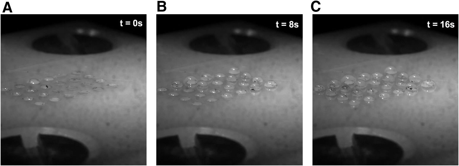
The first test studied a single channel. The electrode corresponding to the channel above a single sphere was activated (15 V), and the platform was lifted such that the sphere on the base plate made contact with the formed droplet. No other droplets were formed since the other channels were not activated. After contact was made, the platform was then lowered, showing the single chosen sphere to have been removed from the platform and adhered to the circuit board. The voltage was switched off, and the sphere continued to stay in place. This illustrates how the device uses low voltages only periodically to control droplet motion until the point of contact beyond which capillary forces of the bridge provide a static holding force in the absence of externally supplied energy.
Another benefit is the self-alignment of objects from the capillary bridges seeking the lowest energy state. Although this behavior was not quantified, it is clearly evident in Supplementary Movie S3 where an out-of-position part (the voxel furthest to the right) is brought to its intended location purely by capillary bridges, at the 7–8 s mark.
Grasping the full array of spheres
The next step was to attempt to pick up all spheres at once using the PICEM. This test was performed 25 times, with 15 V applied to all channels. Success rates for each hole were calculated based on a Binomial Distribution. In the results to follow, the success of the pickup was determined by either a sphere being picked up by an activated channel, or a sphere being left behind by an inactive channel. The lowest success rate was 80%; the highest was 100% for the 25 trials. A mean of 22.72, standard deviation of 1.45, and an average success rate of 90.88% was achieved. To improve the device, a superhydrophobic (SHP) coating was applied via vapor deposition to decrease droplet migration by pinning the drops to the channel circumference. The tests were repeated, and a success rate of 95% was achieved with an average pick up of 23.72 and a standard deviation of 1.7.
Grasping a checkerboard pattern
A checkerboard configuration tested the ability to isolate channels in close contact, while still exhibiting a deliberate pattern seen in Supplementary Movie S2. Further, it allowed for an examination of unwanted droplet growth while picking individual spheres (Fig. 4).
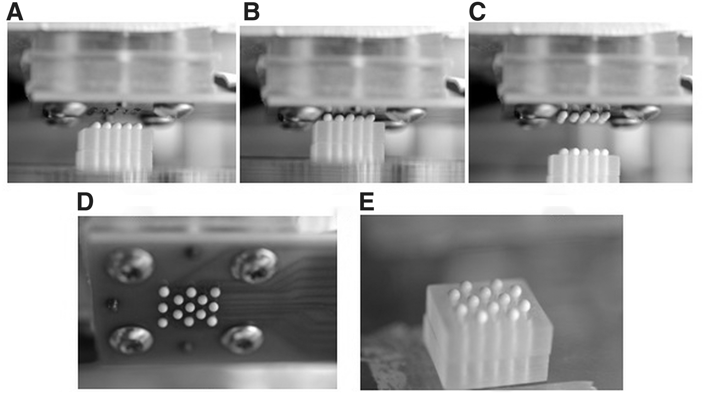
Again, this test was repeated 25 times. The success of the pickup was determined by either a sphere being picked up by an activated channel, or a sphere being left behind by an inactivated channel. Any unwanted pickup was due to contact-line walking or misalignment. The average success for SHP-coated boards was 98% with an average pick up of 24.52 and a standard deviation of 1.6. Other configurations were also tested to assess the accuracy and reliability of the device. These configurations included an “X” shape, “#” shape, small square and top hat shape.
When looking at these statistics, it is also important to evaluate the droplet formation success rate. Some parameters to determine success include looking at how well the PICEM form droplets on the selected channels, and how well it avoided droplet formation on inactivated channels. Quantifying the droplet formation success rate enables whether the electro-osmosis process and the individual addressability features are fully functional and reliable. In all trials, the droplet formation success was 100% for all channels, with zero false-positive droplets formed. This emphasizes the conclusion that platform misalignment and walking of the contact-line are responsible for false-positive pickups.
The lowest success rate for grasping a checkerboard pattern was 67%, whereas the highest was 100%. The mean was 22.80/25, and a standard deviation of 2.52, yielding an average success rate of 90.83%. In these cases, the success of the pickup was determined by either a sphere being picked up by an activated channel, or a sphere being left behind by an inactive channel. More importantly, grasping reliability was not at 100% for the channels. The droplet growth for the checkerboard pattern was shown in every trial, giving a droplet formation success rate of 100% for every intended channel. Any unwanted grasping was caused by droplet walking or misalignment. From there, the SHP-coated boards were tested as seen in Supplementary Movie S2. The results showed much higher success rates. The average success for SHP-coated boards was 98% with an average pick up of 24.52% and a standard deviation of 1.6. Again, despite <100% grasping reliability, droplets were formed in all the desired channels, the results of which are shown in Figure 5.
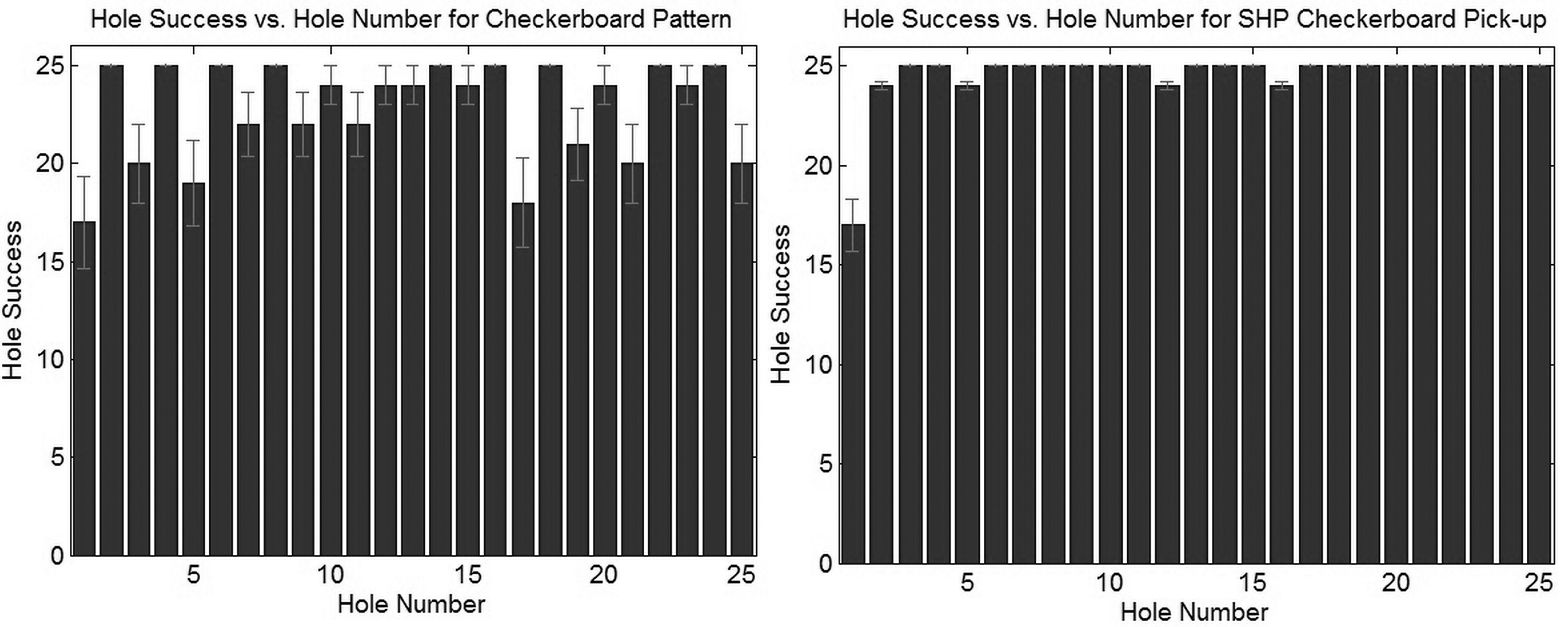
Plots of success rates for picking up checkerboard pattern with error bars for standard deviation. Odd columns correspond to activated channels.
Grasping nonspherical objects and self-alignment
In addition to testing the PICEM with spheres, grasping tests were carried out on voxels with square cross-sections (Fig. 6A–G), and interlocking voxels (Fig. 6H). Grasping was successful, for both square cross-sectioned voxels and interlocking voxels. For both types of voxels, self-alignment based on capillary bridges was evident after contact was made with the liquid droplet as seen in Supplementary Movies S3 and S4.
Velocity measurements
Pick-and-place machines are typically rated on the number of components placed per hour (CPH). In the case of electro-osmotic grippers, CPH is limited by the velocity of the water droplets since droplet dictates how quickly items can be repeatably manipulated. Thus, in this work, velocity is characterized with analytical models and numerical simulation to better understand the liquid motion both through the frit and as a growing droplet.
To experimentally determine the velocity of a droplet coming out of a channel, individual channels were activated with a set voltage (15 V) and images were acquired with MotionPro video analysis software. The time evolution of droplet volume was calculated using a MATLAB routine that combines image analysis with a volume calculation that discretizes the droplet into a Riemann sum of frustum elements. A plot of volume versus time yields the volumetric flow rate from which the velocity can be calculated from knowledge of the channel cross-sectional area, π(0.508) 2 mm2. We note that these temporal variations might be due to higher order effects such as gravity, capillarity, which become more prominent at longer time scales. The average global exit velocity was found to be 0.136 ± 0.024 mm/s.
Discussion
Numerical and analytical velocity measurements
To assess the time scale of the pick-and-place process, it is necessary to accurately predict the velocity for a variety of fluids operating under different experimental conditions such as applied voltage, channel diameter, and frit properties. In the case of electro-kinetic processes, measurement of the double-layer thickness, surface potential, and electric field is crucial to obtaining accurate data. Based on our results, the experimental velocity closely follows the thick double-layer model as seen in Table 2. However, in reality it is more likely that a thin double layer is present. This counterintuitive result can be explained by uncertainty in parameters and sample contamination.
Comparison of Axial Velocity Results (mm/s) Between Experiment, Analysis, and Simulation for Both Thick and Thin Electrical Double Layers
Experimental velocity result is for an uncoated circuit board.
EDL, electric double layer.
It is worth noting that neither the analytical nor simulated solutions incorporate the time-dependent capillary pressure resulting from changes in the droplet curvature as the volume changes. The capillary pressure is in addition to the hydrostatic contribution. Because the pressure term acts as a resistance to the flow, the droplet growth rate will decrease for increasing time, leading to a velocity that also decreases in time. 32
As for the experimentally determined velocities, the spatial variation may be explained by an anisotropic pore distribution and/or channel alignment issues inside the device. In addition, for some of the trials, a few bubbles were generated at the electrode–water interface, suggesting the electrolysis of water into O2 and H2. These bubbles have the potential to get lodged in the frit, thereby decreasing the performance of the device and the droplet exit velocity over time. This problem can be mitigated by using a lower voltage and a different electrode coating and/or working fluid.
To summarize, all velocities predicted with the analytical solution and the simulations will be lower as a result of the effective potential being lower than the applied potential difference. The experimental velocity is likely to be higher at shorter times, where electro-osmosis is the dominant mechanism and the backflow resulting from capillarity has not yet had time to develop. As a result, the experimental velocity can be expected to fall in between the velocities predicted by the thick (lower bound) and thin (upper bound) double-layer models.
Sources of uncertainty
In our case, the parameters with the largest uncertainty are the Debye length and the electric field strength. First, the Debye length is most likely smaller than the theoretical upper limit on distilled water of 970 nm. The distilled water resides in a plastic jug and comes into contact with the air each time the container is opened. Not only is there dissolution of
From Table 2, we see that there is agreement between the analysis and the simulation. This is expected, since the set of equations used in the simulation reduces down to the same equation as the analytical solution under conditions of steady state. Notice that the predicted velocity in the case of a thick double layer is the same as the experimental value whereas in the case of a thin double layer, the predicted velocity is two times greater. The discrepancy might be explained by the uncertainty in the electric field, since electric potential was derived under the assumption that both the point charge and the infinite plate were suspended in a medium with a permittivity equal to
The diversity of the materials along the entire electric field lines from the reservoir to the outlet of the circuit board channel presents additional challenges. Some of these materials (i.e., the Tango+) absorb water, thereby increasing the dielectric constant in those regions. If an inactivate channel does experience flow, the velocity ends up being small because the radial transmittance of the field is substantially decreased as a result of water absorption.
Finally, as a result of the capacitive effect of the double layer, the effective potential difference is decreased even further and becomes a time-dependent quantity. For a similar setup, 32 it has been found that the effective potential difference is around half of the applied value. Their model takes into account the resistance of the electrode, fluid, and the frit in addition to the capacitive effects of the electrode. A lower electric potential corresponds to a smaller electric field, and a smaller electric field corresponds to a smaller velocity. This holds true irrespective of the double-layer thickness. Charge accumulation within the droplet further impedes velocity and droplet growth over time.
Sources of error
As for the permeabilities, the outsourced average permeability was about half of the analytical and manufacturer's value. This could be due to errors in the experimental testing of the frit. The frit was epoxied on the sides to reduce the chance of water flowing around and not through the frit. Since the frit is a porous medium, the epoxy is absorbed by the frit, and it may have contaminated some of the areas being tested. If epoxy were to enter into the testing region, it would decrease the flow through the material, therefore decreasing the permeability.
Finally, the capillary pressures for the frit from both experimental testing and porometer measurements data were very close. Differences between the two are attributed to testing a different frit than what was used in the experimental testing. Since each frit is slightly different in permeability, pore size, and pore distribution, it is possible that there would be variances among the two frits that would cause for this discrepancy.
PICEM grasping reliability
The accuracy and reliability of the PICEM device are best shown by the checkerboard pattern tests, which showcase the individually addressable capabilities of the PICEM. Success rates were high in all trials, but a much higher success rate could be achieved with more precise mechanical apparatuses moving the PICEM. For instance, the parallelism between the platform array and circuit board face could be improved. This loss of parallelism resulted in inconsistent grasping, especially around the edges, as shown in the data. However, since the PICEM did have a 100% success rate on creating droplets in the desired configurations, future work can address these sources of error in the mechanical environment to increase grasping success rates.
Since the current design has 508 μm diameter channels for droplet growth, it has a limited ability to pick up small objects with maximum dimensions around this range. As the device can be easily customized, future revisions can be custom built to match the density and diameter of the channels as needed. The PICEM can grasp objects ranging from 2 mm (based on the capillary length of the liquid, which in this case is water), to sub-micron scale.
Error correction and scalability
The error rates in the present state of electro-osmotic gripping are not suited for million-component assemblies. Generally speaking, denser, larger objects will be more challenging to grasp and may require slower operation, whereas smaller, sub-millimeter scale objects will be easier to grasp but more challenging to release. Similarly, asymmetrical and irregularly shaped objects may pose unique challenges for accurate electro-osmotic gripping as they may self-align on the PICEM in unpredictable ways.
The errors observed in this work were random however, as with any mechanical system, we expect clogging, mineral buildup to contribute to clogged grippers. Error rates can be improved by using higher precision gantries, voxel jigs, and voxels, and they can sufficiently minimize error and uncertainty. In addition, error correction could be performed if computer vision systems are added in the operation loop of LA.
Conclusion
This work has shown that electro-osmosis is a viable method to achieve the selectively parallel grasping that is necessary for LA. The close agreement between experimental testing, numerical simulations, and analytical calculations validates that electro-osmosis can be reliably used in an individually addressable, arrayed device to enable low-power, solid-state pick up of objects. The basic physics of the PICEM can be accurately captured with a simple model, whereas statistical analysis of parallel grasping shows that the PICEM is a reliable and accurate means of selectively parallel manipulation of mm-scale spheres.
Electro-osmotic LA is particularly well equipped for grasping smaller objects since solid-state gripping methods are inherently more scalable for both larger component counts and smaller component sizes as they do not rely on electromechanical actuators or solenoids.
Looking forward, the array size of the circuit board can be expanded to hold millions of channels. Expanding this 5 × 5 array to a larger scale will only require larger circuit boards and a slightly more complex control system. Although the device is currently controlled by manually connecting a voltage source, this control can be automated so it is software-driven. This would allow for both positive and negative voltage to be used simultaneously to ensure that each droplet is uniform and consistent among the array.
The ultimate goal of LA is the massively parallel assembly of nanofabricated tiles that are small enough to appear as sand particles. These tiles could be aligned with a vibrating tray, and the PICEM would be able to hold a million channels that are capable of selectively grasping tiles as necessary. However, on a grander scale, this device could be used to pick up objects of varied size, and has the ability to stack these objects, and to have an integrated control system to ensure desired droplet size and picking ability. Moreover, additional liquids could be used for different desired surface tensions, tailored to the particular surface materials of the objects to be picked.
Footnotes
Acknowledgments
In memory of the late Professor Paul Steen (1952–2020) who was renowned for his work in interfacial fluid mechanics and in microgravity research. Additionally, the authors extend a special thanks to the Steen Group in their support for their initial training on the SECAD. Further, prior work from Jonathan Hiller served an integral role in the automation of this device, and to Mike Vogel for his previous work on the SECAD.
Author Disclosure Statement
No competing financial interests exist.
Funding Information
This work was supported by Defense Advanced Research Projects Agency National Science Foundation Grant No. W911NF-11-1-0093 and NSF Grant No. DGE-0707428.
References
Supplementary Material
Please find the following supplemental material available below.
For Open Access articles published under a Creative Commons License, all supplemental material carries the same license as the article it is associated with.
For non-Open Access articles published, all supplemental material carries a non-exclusive license, and permission requests for re-use of supplemental material or any part of supplemental material shall be sent directly to the copyright owner as specified in the copyright notice associated with the article.