
Abstract
Additive manufacturing of fiber-reinforced polymers is one of the latest technical developments in composites manufacturing. However, there is a severe shortage of research into continuous fiber-reinforced polymers manufactured through stereolithography. For the first time, this article investigates the fracture properties of continuous carbon fiber-reinforced polymer produced by three-dimensional stereolithography printing. Compact tension (CT) specimens, both plain and fiber reinforced, were produced and tested systematically. The results showed a significant improvement in fracture toughness for fiber-reinforced specimens when compared with plain ones. The positioning of fiber bundles had a substantial effect on fracture properties, and a higher fracture toughness was reported for specimens with the fiber bundle placed closer to the crack tip. By increasing the number of fiber bundles, a significant increase in fracture toughness was reported when compared with the sample with a single fiber bundle, indicating a strong contribution of fiber volume. Also, the contribution appeared to be most effective when the fiber bundles were placed symmetrically in the thickness direction. The study is of importance and value for the development of the stereolithography technique in manufacturing continuous fiber-reinforced composites with enhanced mechanical properties.
Introduction
Stereolithography (SLA) was the first additive manufacturing (AM) process that has been developed. 1 The process employs rapid curing of a photosensitive resin under ultraviolet (UV) laser irradiation. Printing parts with this method offers high precision and creates a good quality surface. However, polymers printed using SLA show inferior mechanical properties in terms of strength and durability for load-bearing applications. 2 These drawbacks limit the use of additively manufactured parts for structural applications, thus hindering the development and application of the SLA for end users. Introducing fiber reinforcement into SLA can improve the mechanical properties of additively manufactured structures, enabling more broad use of the process for high-value applications.
Short-fiber-reinforced composites have been widely used in AM, but offer limited improvement in mechanical properties.3–5 Continuous-fiber-reinforced composites more effectively improve mechanical properties. By controlling the distribution and direction of continuous fibers, tailored mechanical properties can be achieved. Currently, making continuous-fiber-reinforced composites with AM is mainly based on material extrusion. The world's first commercial three-dimensional (3D) composite printer, the Mark One, was developed in 2014. 6 The printer adopts a double nozzle setup with one for matrix filament and the other for continuous fiber. Through the combination of two nozzles, composite printing with controllable fiber distribution is achieved.
However, for material extrusion, poor bonding between extrusions and layers remains an issue, which is a fundamental limitation of the material extrusion process itself. For instance, Der Klift et al. 6 conducted tests on carbon fiber composite samples printed using the Mark One printer. It was reported that with increasing fiber content, more pores appeared inside the composite material, which limited mechanical properties. 6 Melenka et al. evaluated the elastic properties of printed fiber-reinforced structures and predicted their elastic properties using the average stiffness method. 7 The differences between measured and predicted values were mainly caused by poor bonding between fiber and the matrix.
Compared with material extrusion, SLA has advantages in accuracy and bonding, and the photosensitive resin has a similar chemical structure to epoxy resin used in the conventional composites industry. Greer et al. attempted to fabricate composites using SLA technology, and continuous carbon fibers as the reinforcement. 8 In this study, the continuous carbon fibers were arranged in a uniform direction and solidified with the photosensitive resin to obtain unidirectional fiber composite specimens. The tensile strength of the specimen was as high as 122.6 MPa for a fiber volume fraction of 25.9%, which was four times that of the pure resin specimen.
Karalekas added fibrous nonwoven mats to each layer during the SLA process to obtain epoxy resin-based glass fiber composites and acrylic-based carbon fiber composites. 9 Both tensile strength and modulus of elasticity were significantly improved compared with pure resin materials. However, studies related to SLA-printed composites are rare due to the difficulty in machine operation (mostly bottom-up type). So far, no commercial SLA machine is available for composite manufacturing, but there is the potential for such a machine.
To date, most research about 3D printed continuous fiber composites produced using AM puts emphasis on improving mechanical properties such as tensile and flexural strength. Li et al. manufactured continuous carbon fiber-reinforced polylactic acid (PLA) composites using the material extrusion technique. 10 They designed a novel nozzle to allow simultaneous impregnation and extrusion in the liquefier of printing head. The resulting carbon fiber-reinforced composite exhibited better mechanical properties than pure PLA, but offers a weak interface bond between the carbon fiber and PLA. Thus, carbon fiber bundles were infiltrated with PLA before printing, resulting in a substantial improvement of interfacial strength.
Tian et al. carried out a similar study using carbon fiber to enhance the mechanical properties of PLA. 11 By changing processing parameters, the fiber content of the printed specimens was controlled. When fiber content was increased to 27%, the printed composite specimens reached a flexural strength of 335 MPa and modulus of 30 GPa, showing a considerable improvement. Zhao et al. mixed micro-size poly(p-benzoyl-p-phenylenediamine) (Kevlar) fiber into the resin for SLA. 12 The mixed resin was solidified by a projector beam (405 nm) in the z-axis direction, layer by layer. The results showed that, after UV light irradiation and thermal curing, the strength and Young's modulus of the composite were 1.79 times and 11.2 times higher, respectively, when compared with those of the pure resin.
Fracture toughness is a critical aspect of a component's strength and structural integrity. Fracture toughness indicates the material resistance to crack and acts as a key mechanical property for 3D printed materials. Recently, research has been carried out to investigate the fracture toughness of additively manufactured parts. Mclouth et al. 13 printed compact tension (CT) samples using acrylonitrile butadiene styrene (ABS) filament in three different directions (i.e., the sample's bounding box being aligned parallel to the x, y, and z-axes of the build platform), and analyzed how they affected fracture toughness. 13 The results showed that the fracture toughness increased by 54% when the filament alignment was changed from a parallel direction to a perpendicular direction with respect to the crack plane.
Hart and Wetze studied the fracture toughness of 3D printed ABS samples produced using a material extrusion method, where brittle behavior was observed during interlaminar fractures and ductile properties were observed for cross-laminar fractures. 14
In addition, efforts have also been made to study the fracture toughness of additively manufactured composites. Papon and Haque fabricated CT PLA samples reinforced with short carbon fibers using material extrusion. 15 They mixed PLA pellets and carbon fibers in a homogenizer with different fiber content. A single screw extruder was used to fabricate the composite filament. They also developed a customized square nozzle to improve the bond strength by reducing the amount of inter-bead voids. The fracture toughness of printed samples with a 5% volume fraction of carbon fibers was increased by 42% and 35% for 0°/90° and 45°/45° bead orientations, respectively.
Swolfs and Pinho printed CT samples with glass fibers and local carbon fiber strips as reinforcement, and a 20–60% of improvement was found for fracture toughness. 16 Akasheh and Aglan used a Mart Two printer to print single-edge notched samples. 17 The 3D printed composites utilized carbon fiber bundles to reinforce nylon/chopped-fiber composite in a multilayered structure configuration. This study found that wrapping fiber around the notch effectively blunted the notch root and redirected crack propagation away from the notch tip, thereby lengthening the crack path and leading to improved fracture resistance.
However, in the studies discussed earlier, the samples were additively manufactured through the material extrusion method, and the fracture toughness for SLA-printed fiber-reinforced composites has not been well studied yet. A fundamental understanding of the fracture mechanics of 3D printed carbon fiber-reinforced plastic composites using SLA is crucial for the development of the SLA technique in design and manufacturing continuous fiber-reinforced composites.
To fill this research gap, the objective of this study is to assess fracture toughness of SLA-produced composites with respect to the positioning and volume of carbon fiber bundles. The samples were made from a clear 04 UV resin on an SLA printer (Form 2), reinforced with continuous carbon fiber bundles. A series of CT experiments were conducted to determine the fracture toughness of SLA printed composites, in comparison with that of pure resin samples.
Methodology
Materials and manufacturing
Clear 04 UV-resin, obtained from Formlabs Inc., was used for producing the matrix. The UV-cured resin has a tensile modulus of 2.8 GPa and an ultimate tensile strength of 65 MPa. A fiber bundle containing 3000 single carbon fibers (i.e., 3K-fiber bundle) was used as reinforcement. The tensile modulus, strength, and density for this fiber bundle are reported as 238 GPa, 4.12 GPa, and 1.79 g/cm3, respectively, according to the manufacture data sheet (Easy Composites). The polymer matrix was manufactured using a bottom-up SLA printer (Form 2; Formlabs, Inc.).
The machine operates with an UV radiation beam of 405 nm and a laser spot size of 140 nm. A 50 μm layer thickness was chosen to balance the tolerance and printing speed in the printing process. 18 The UV light is irradiated onto the photosensitive resin through the bottom of the transparent resin tank to complete the curing process at the bottom of the working platform. After the curing is completed, the working platform is raised by the height of a single layer and the resin automatically fills the one-layer gap for the next curing process. The newly cured layer bonds to the previous layer, and so on, until the entire part is manufactured.
The machine was a standard Formlabs Form 2 SLA printer designed for printing samples out of pure resin, but used in this study to print samples reinforced with carbon fiber bundles. A similar approach was also adopted in existing studies where the printing parameters were kept the same as those for printing pure resin.
Sano et al. used an SLA printer to produce composites with the machine's built-in printing parameters, that is, a wavelength of 405 nm and a resolution of 0.3 mm in the x–y plane (printing plane). 19 They used glass powder, glass fiber, and plain-woven fabric as fillers to print samples that showed enhanced mechanical properties. Manapat et al. used a Formlabs Form 1+ printer, equipped with a Class 1 405 nm violet laser with a power of 120 mW and a spot size of 155 μm, to print composite samples out of Formlabs gray resin mixed with graphene oxide. 20 They were able to produce materials with improved mechanical properties and complex shapes using a layer thickness of 50 μm.
Zhao et al. used an Advanced Micro digital light processing (DLP)-1 3D printer to manufacture composite samples out of photocurable resin with added Kevlar fiber. 12 The DLP printer operated with a light source wavelength of 405 ± 10 nm, an exposure time of 5 s per layer and a layer thickness of 80 μm. When the content of Kevlar reached 7 wt%, the printed samples showed significant improvement in strength and Young's modulus (1.8 and 11.2 times higher, respectively) when compared with those of the pure resin.
In all aforementioned studies, researchers used the same printing parameters as they used for pure resin and successfully made the composite samples with good precision and enhanced mechanical properties.
Specimen production
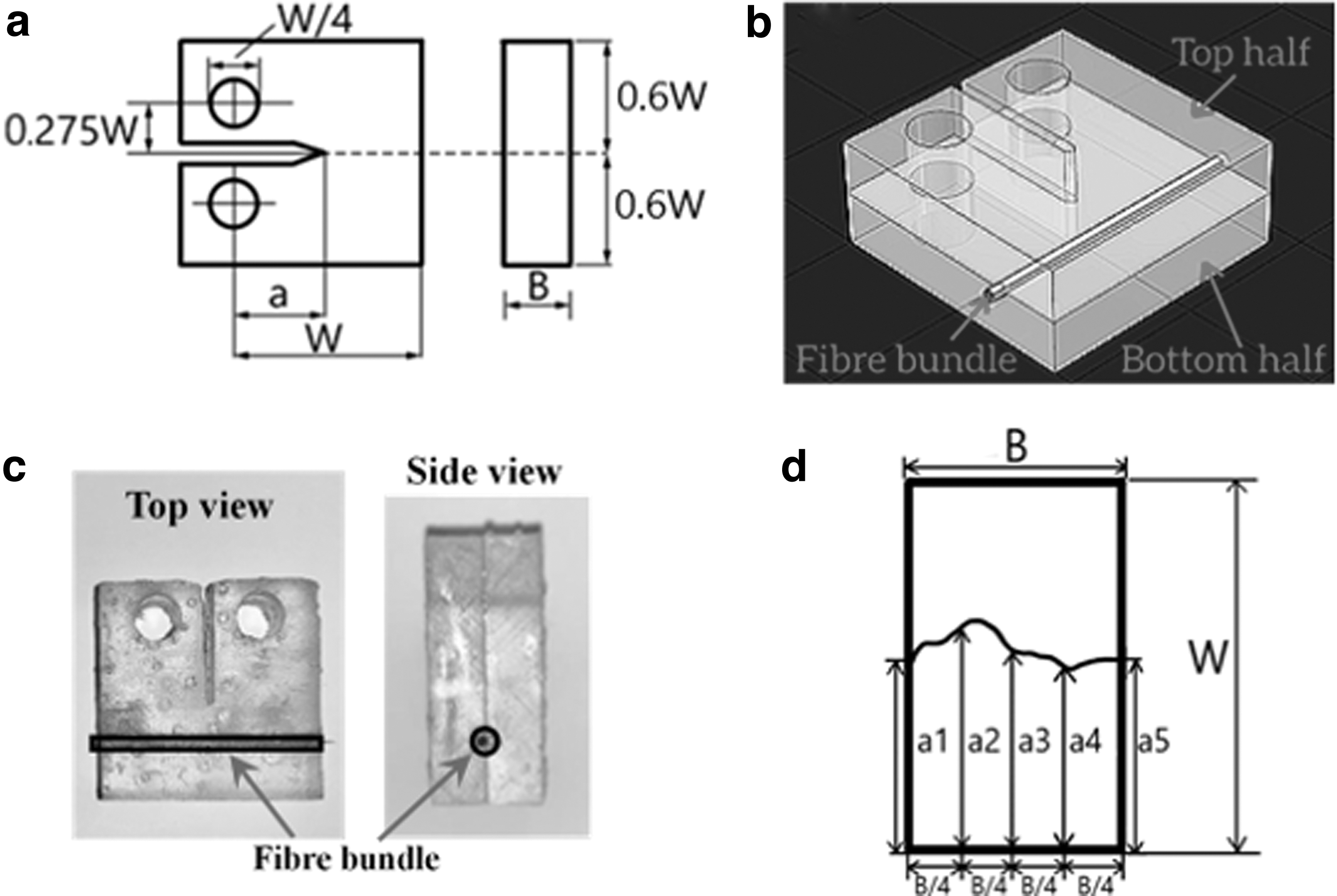
The CT specimen used for fracture toughness testing is shown in Figure 1. The specimen width W is chosen to be 24 mm, and the specimen thickness B is set as 12, 6, and 3 mm, respectively (Fig. 1a). The samples were printed in two halves with a slot in between for fiber insertion (Fig. 1b). To shape the fiber, the fiber bundles were coated with a thin layer of Clear 04 resin using a soft paint brush. Then, these bundles were post-cured for 2 h in the UV oven. The straight shape of the fiber bundles was achieved by hanging a weight at the end. A pre-shaped fiber bundle was put inside the slot and the two halves were adhered together using Clear 04 resin.
Similar manual manufacturing processes have been widely used in hand layup methods for manufacturing conventional composites.21,22 Recently, the method has also been introduced into 3D printing of composite samples. Yao et al. embedded continuous carbon fiber tows into a PLA structure during the fused deposition modeling (FDM) printing process. 23 They impregnated and pre-shaped the fiber using epoxy resin adhesive, then manually placed them on the specified printed layer. The specimens reinforced with carbon fibers had a 70% increase in tensile strength and an 18.7% increase in flexural strength compared with nonreinforced specimens.
Billah et al. also embedded continuous bundles of carbon fiber into FDM printed polycarbonate (PC) substrates. 24 They dissolved chopped PC filament in a dimethyl chloride solution and then impregnated continuous fibers in this mixed solution. All impregnated CF tows were dried for 2 h inside a fume hood. The pretreated fiber was then pressed onto a certain layer manually using ultrasonic embedding apparatus for a better interface bond, resulting in a 60% increase of the tensile strength due to fiber reinforcement.
The printed specimens were post-cured for 2 h in the UV oven to complete production (Fig. 1c). Razor blade tapping was then used to generate a pre-crack for the CT specimens by following the American Society for Testing and Materials (ASTM) D5045 standard. 25 The pre-crack length was measured for each specimen after testing and then added to the initial crack length a for the calculation of fracture toughness.
Fracture toughness test
Fracture toughness tests were conducted on CT specimens using an Instron 3366 tensile test machine with a load cell capacity of 10 kN. The load was applied at the top hole of the sample, whereas the bottom hole was constrained. The load and crack opening displacement (COD) were recorded with data acquisition software at regular intervals until the maximum fracture load of the specimens. According to ASTM D5045,
25
the critical stress intensity factor (KIC) was determined using the following equations:
where
For crack length, measurement was taken on the fracture surface of tested specimen with a microscope. As the crack front has an irregular feature, crack length was measured at five equally spaced positions along the thickness direction (Fig. 1d), with the average value taken for toughness calculation.
Results and Discussion
Effect of specimen thickness (plain sample)
To study the effect of specimen thickness, CT samples were manufactured with a thickness of 12 mm (standard), 6 mm (50% reduction), and 3 mm (75% reduction); all subjected to the same testing conditions. Figure 2 shows the representative load-COD plots for samples of various thickness. The load first increased in a linear relationship with COD, followed by a sudden drop that represents the final fracture. The figure also shows that the load-bearing capacity of the specimens is decreased along with reducing sample thickness. From the attached picture, a smooth and shiny fracture surface can be seen, which is perpendicular to the principal stress direction (load direction), indicating brittle fracture nature of this sample.
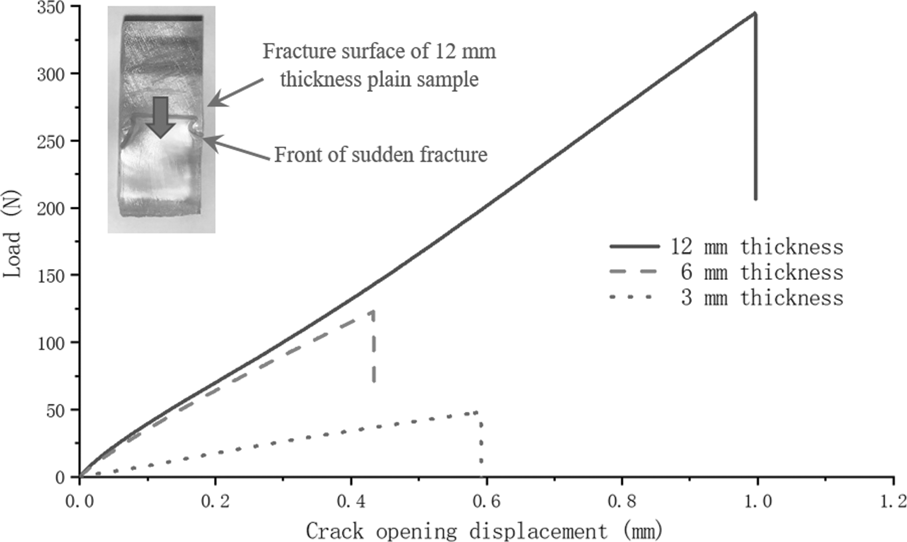
Representative load-COD plots for plain samples with varied thickness. COD, crack opening displacement.
Table 1 compares the average fracture toughness of the samples with a thickness of 12, 6, and 3 mm, respectively. The decrease in thickness from 12 mm and 6 mm resulted in a reduction in KIC, from 1.427 MPa
Fracture Toughness of Plain Samples with Varied Thickness
Fracture toughness tests are generally carried out under plane strain conditions, where the crack tip undergoes a limited zone of plastic deformation. As such, brittle fracture is prone to happen, leading to a lower value of fracture toughness than that obtained under plane stress conditions. However, the samples made in this study showed the opposite behavior. The brittle nature of the material meant that the sample thickness did not change the plastic zone size, and a brittle fracture could always be found despite the change in thickness, thus making the thickness have limited effect on fracture toughness. In the following studies, the 12 mm thickness was chosen to fabricate the CT samples to prevent buckling and also to provide more space to accommodate the fiber bundles.
Effect of post-curing times (plain sample)
When the 3D printing is completed, the parts on the build platform are still in a “green state.” The liquid resin used in an SLA 3D printer is a mixture of free monomer and a photoinitiator. When this mixture is exposed to UV light, it causes the photoinitiator to react, making the free monomers to combine into a solid polymer. The cured resin is a cross-linked macromolecular polymer. However, if the parts fail to achieve the desired degree of cross-linking after printing, the tensile strength and other properties of the workpiece will be affected.
Post-curing with UV light completes the molecular bonding process to ensure that the highest degree of cross-linking is achieved. Although this process can increase the strength of the workpiece, it can also decrease its toughness. To study the effect of post-curing, three samples with the same geometry but various thickness (i.e., 3, 6, and 12 mm) were printed and post-cured for 2 h before testing.
Figure 3 shows the representative load-COD plots for the samples that underwent 2-h curing. Compared with the results without post-curing, there was a large decrease in fracture toughness, that is, by 45.13%, 51.10%, and 51.12% for the samples with a thickness of 12, 6, and 3 mm, respectively (Table 2). The post-curing process led to more brittle behavior and decreased the energy consumed for the fracture, resulting in a significant reduction in fracture toughness. Also, the fracture surface (inset picture) was found to be shiny and smooth, which demonstrates the brittleness of the fracture behavior.

Load-COD plots for post-cured samples with varied thickness.
Fracture Toughness of Post-Cured Sample with Different Thickness
Effect of reinforcing fiber bundle and positioning
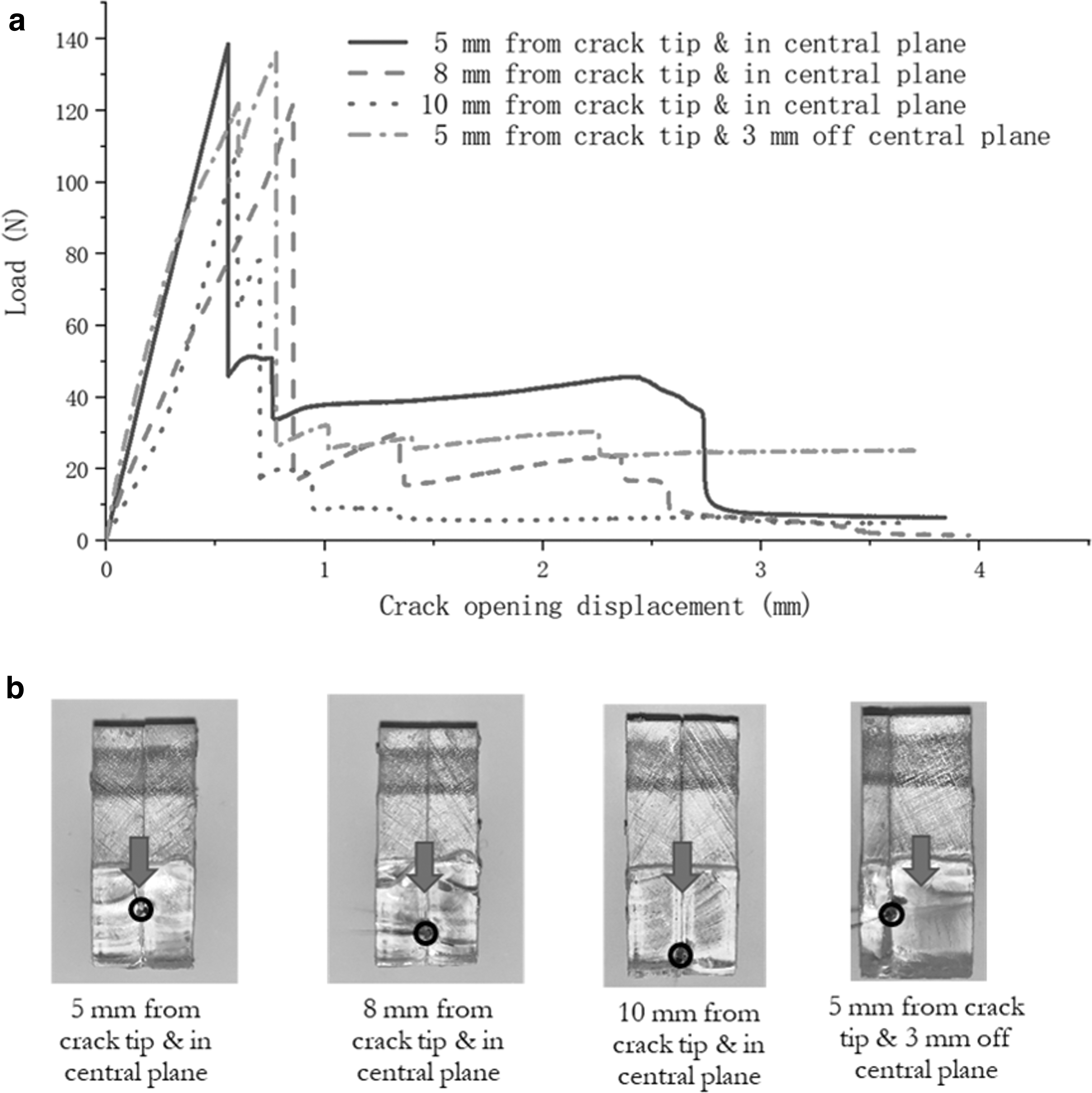
To test how carbon fiber could improve fracture toughness of the printed specimens, a 3K-fiber bundle was added to the plain sample. To study the effect of fiber positioning on the fracture toughness, the same carbon fiber bundle was inserted at different locations. Specifically, the fiber bundle was placed on the central plane along the thickness direction, with distances of 5, 8, and 10 mm from the crack tip. In one sample, the fiber was shifted by 3 mm from the central plane, whereas the distance to the crack tip was kept at 5 mm. The representative load-COD response for each sample is shown in Figure 4, with the average fracture toughness given in Table 3.
Effects of Reinforcing Fiber Bundles and Positioning on Fracture Toughness
Compared with the results for plain samples in Figure 3, the responses were rather similar before reaching peak load, that is, there was almost a linear increase for the fiber-reinforced samples. However, after the fracture occurred, the force dropping trend was different from that of the plain samples. Despite there being a similar sudden drop at peak load, a small increase followed by a second drop in load was observed for reinforced samples.
The average fracture toughness is recorded in Table 3, and was calculated as 0.846 MPa
Fracture toughness is defined as the energy a material can absorb before breaking. The brittle photosensitive resin alone cannot absorb much energy, so their toughness is relatively low. When the material was reinforced with carbon fibers, the rupture changed from a simple and clean breakage to cracks along the fiber–resin interface. This will lead to the development of delamination along the fiber–resin interface, delaying the whole fracture process. The crack changed from growth only in the matrix to a delamination process along the fiber–resin interface.
The first drop that can be seen in Figure 4a is due to the breakage of the resin matrix between the initial crack tip and the fiber bundle, and the second drop is due to the failure caused by delamination along the fiber–matrix interface. Therefore, the amount of energy consumed for a whole fracture to take place increased and resulted in a higher fracture toughness. Jia and Wang 26 concluded that the heterogeneity made the materials tougher. They indicated that when a crack propagated from a less stiff material toward a hard material, the driving force at the crack tip was significantly reduced and crack propagation tended to be stopped. 26 A soft-to-stiff material property change plays an essential role in increasing the toughness of heterogeneous materials. Jia and Wang 26 also concluded that introducing a soft interface can toughen the material as well.
This finding is also consistent with Swolf's results, 16 based on a finite element model of CT test. The model used nylon reinforced with glass fiber as a matrix and nylon reinforced with carbon fiber as a reinforcement. Their results demonstrated that the transition from a less stiff material (glass fiber-reinforced nylon) to a stiff material (carbon fiber-reinforced nylon) could indeed increase the translaminar fracture toughness. In our results, the photocurable resin for matrix is less stiff than the continuous carbon fiber, and when a crack propagates from the resin to the fiber, the crack tends to be arrested. Also, the interface between the resin and the fiber can guide the crack to move along the interface, which also slows down the crack propagation and thus increases fracture toughness.
Clearly, the addition of carbon fiber bundles increased the fracture toughness and also increased the time required to completely fracture the material. Based on our results, specimens with fibers positioned at 5 mm from the crack tip had the most significant improvement in fracture toughness, followed by the specimens with fibers positioned at 8 mm from the crack tip. The increase in fracture toughness was almost negligible when the fibers were positioned at 10 mm from the crack tip. Akasheh and Aglan also found out that having fibers wrapped around the notch can improve the fracture resistance, leading to an increase in fracture toughness of 11.18% compared with standard reinforced samples. 17
In our results, with fiber bundles placed nearer to the notch, more effective toughening of the material was also found. When the fiber is placed closer to the crack tip, a crack will begin to grow along the interface after a short period of brittle behavior. There is also more energy consumed compared with the cases where fibers were put further from the crack tip, as these underwent a longer state of brittle cracking. When fibers are positioned off the center plane (thickness direction), they also enhance fracture toughness.
However, due to the asymmetric positioning of the fibers, the fracture toughness was not increased as much as it was for the symmetric samples. One possible reason for this is that the positional asymmetry results in unbalanced stress in the thickness direction, causing the crack to grow easier on the side without fibers. Thus, the whole fracture process will be quicker, with less energy absorbed, resulting in a lower fracture toughness.
Figure 4b shows the fracture surfaces of the samples with various fiber bundle positions, where the line indicates the front of a sudden fracture. Although the shiny and smooth fracture surface still indicates a brittle fracture process, there are more lumps and bumps around the fiber bundle compared with the plain samples, suggesting a slowdown of crack growth speed. To conclude, the positions of the fiber bundle affect the fracture characteristics of the sample considerably. When the fiber bundle is placed closer to the crack tip, a higher fracture toughness is achieved. Also, when fiber bundle is positioned off the central plane in the thickness direction, the enhancement of fracture toughness is not as effective as the centrally positioned case, due to the asymmetry of fiber-bundle positioning.
Effect of multiple fiber bundles and positioning
In composite materials, a larger proportion of carbon fibers often means improved mechanical properties. To investigate whether this is also applicable to fracture toughness, the number of carbon fiber bundles placed in samples was increased from one to three, and placed at 5, 8, and 10 mm ahead of the crack tip, simultaneously (three fiber bundles were placed along the central line). Also, to test whether the positioning of the three fiber bundles had an effect on the fracture toughness, the fiber bundles were all placed at 5 mm ahead of the crack tip, but two of them were shifted by 3 mm in the thickness direction (three fiber bundles across the sample thickness). The volume of fibers used in the two experimental groups was kept the same. All samples were subjected to a fracture toughness test, with the results presented in Figure 5 and Table 4.
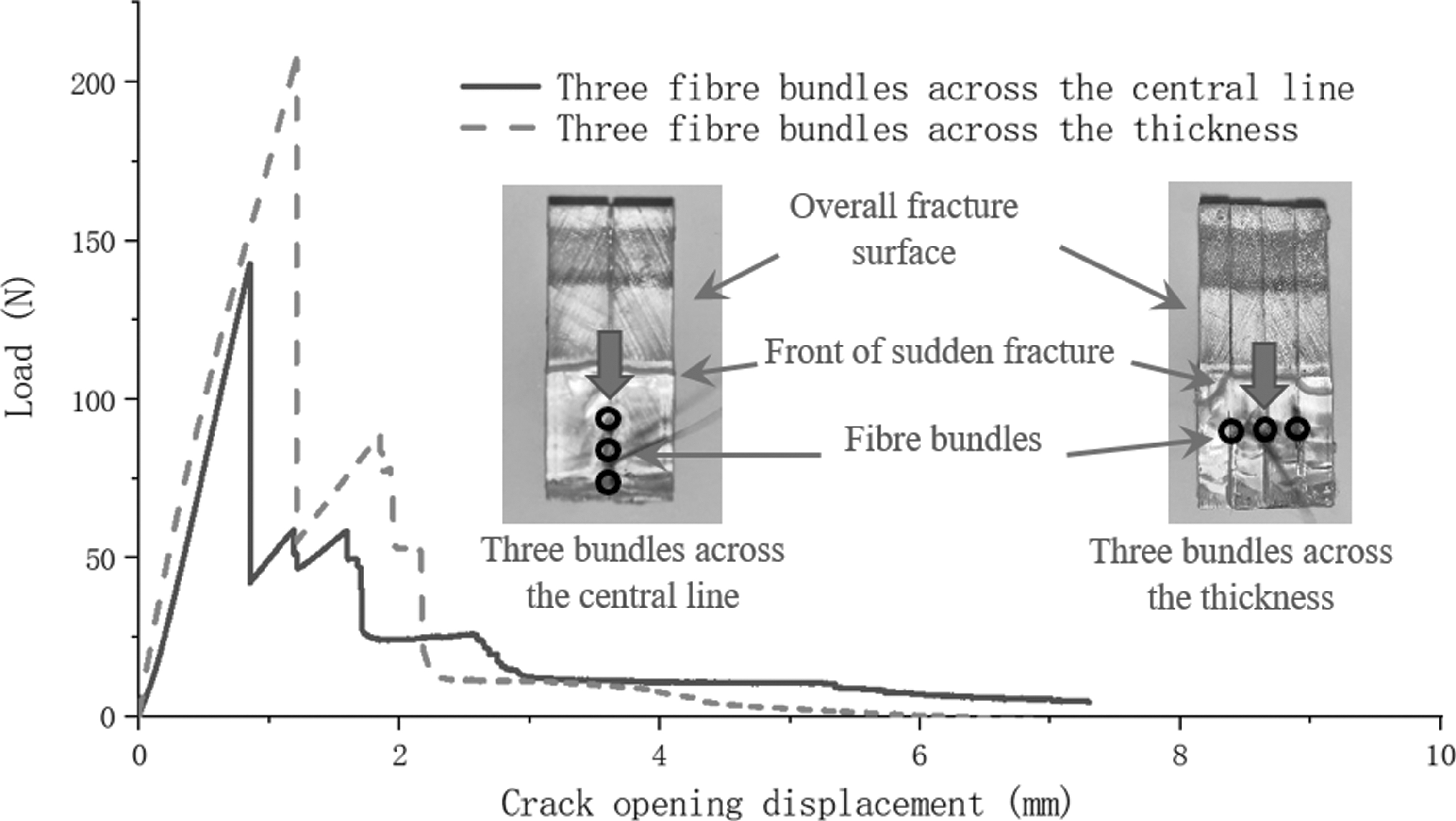
Representative load-COD plots: effects of multiple fiber bundles and positioning.
Effects of Multiple Fiber Bundles and Positioning on Fracture Toughness
For the three fiber bundles placed in the longitudinal direction, the overall trend of the load-COD response before reaching the peak load was very similar to the previous cases. The load experienced a sudden drop after reaching the peak point. Unlike the previous results, the force experienced several small rises and drops after the first sudden drop, resulting in an increased area under the curve. As a result, the average fracture toughness of these samples was obtained as 0.948 MPa
This result is consistent with Swolf's findings where improvements in fracture toughness can be obtained by increasing the number of fiber bundles. 16 This proves that incorporating material transitions (i.e., from the matrix to fiber) is a potential strategy for increasing the translaminar fracture toughness. The addition of more fiber bundles means that when a crack grows, brittle fractures will be suppressed further by causing a delamination along the multiple interfaces between fibers and the matrix. This behavior will increase the energy required for a fracture to occur, resulting in an increased fracture toughness.
For the three fiber bundles placed symmetrically in the thickness direction, the force had a greater upward trend after the first sudden drop. The average fracture toughness was calculated as 1.045 MPa
These multiple interfaces absorbed a substantially higher amount of energy during the crack growth, and the total energy required for the whole fracture process increased, resulting in an increased fracture toughness. The fracture surface still suggested that all of the samples were still rather brittle. Also, the cross section was smoother before the crack propagated toward the fiber bundle.
The increase in fracture toughness with fiber volume is comparable with Papon and Haque's study with fiber-reinforced CT samples produced by FDM. 15 In their study they mixed PLA pellets and carbon fibers in a homogenizer with different fiber content to make composite filament and made CT PLA samples reinforced with short carbon fibers using the material extrusion process. In their results, the increase was 34.09% and 45.45% for 3 wt.% and 5 wt.% carbon fiber contents, respectively. This exhibited an effective increase in KIC with increasing fiber content. In our experiments, the weight fraction of a single fiber bundle was around 2 wt.%. When fiber bundles were placed near the crack, the fracture toughness showed a 31.28% increase.
When the fiber volume was increased to around 5 wt.% (three fiber bundles embedded), the increase of fracture toughness reached 62.27%, confirming that embedding continuous carbon fibers into SLA printed parts have great potential for increasing fracture toughness. Also, in our study, three replicates were produced and tested for each set of samples, and the fracture toughness showed consistent trends. The differences between the three replicates were marginal (<5%), with a small standard deviation, as stated in Tables 1–4. Our future study will include finite element modeling of the fracture toughness for our printed samples to further investigate the dependency of fracture toughness on fiber location and volume.
It should also be noted that, presently, no commercial SLA machine is available for manufacturing composites through AM. Therefore, a fiber-insertion method was used in this study to evaluate the properties of continuous carbon fiber composites printed by SLA. This semimanual method replicated the way that fibers would be added during the printing process as much as possible, but drawbacks may still exist. First, the curing time of the resin used to bond fibers and the matrix may not match that which is used in the printing process, and the interface might, therefore, be cured differently. Second, artificial errors may have been introduced as the amount of resin applied to fibers and matrix may have varied slightly each time. These drawbacks can be overcome with an automated manufacturing system.
Despite the shortcomings in the production method, the results of this study provide a valuable reference regarding the effect of fiber reinforcement on fracture toughness. Placing fibers along the path of a crack can slow down crack propagation, leading to a significant increase in the toughness of a product. This effect can be further utilized in 3D printing through free placement of the fibers. In the future, our study will develop an automatic SLA system that can replicate this manual process, allowing fibers to be implanted during the printing process.
Conclusions
This study produced both plain and continuous fiber-reinforced CT samples using SLA. A series of experiments have been carried out to investigate the effects of sample thickness, post-curing time, fiber volume, and fiber position on the fracture toughness of 3D printed samples. The decrease in thickness resulted in a sharp decline in fracture toughness due to the brittle nature of the material. The post-curing process made the polymer even more brittle, resulting in further reduction in the fracture toughness. The addition of a 3K-fiber bundle into the CT samples increased the fracture toughness substantially compared with the plain samples.
The fiber-bundle position also affected fracture properties, and an increased fracture toughness was obtained when the fiber bundle was placed closer to the crack tip. When the fiber bundle was positioned off the central plane in the thickness direction, the enhancement of fracture toughness was less effective due to asymmetry of the fiber positioning. Placing a row of fiber bundles across the thickness direction and close to the crack tip produced a greater improvement in fracture toughness compared with placement of fiber bundles in a single row along the longitudinal direction. The study is valuable for the future development of the SLA techniques to manufacture continuous fiber-reinforced composites with enhanced mechanical properties.
Footnotes
Authors' Contributions
Y.L., X.X.H., L.G.Z., and A.G. contributed to the research and the preparation of the article. Y.L. carried out the study, processed the results, and drafted the article. X.X.H., L.G.Z., and A.G. supervised the technical work and also contributed to discussions, writing, and editing of the article.
Author Disclosure Statement
No competing financial interests exist.
Funding Information
No funding was received for this article.