
Abstract
This work explores additive manufacturing (AM) of concrete by using a six-axis robotic arm and its use in large-scale, autonomous concrete construction. Concrete AM uses an extrusion method to deposit concrete beads in layers to create a three-dimensional (3D) shape. This method has been found to have many uses and advantages in construction applications. The lack of formwork and autonomous nature of this manufacturing method allows for new geometries and materials to be printed in unsafe or challenging environments. Autonomous construction has been suggested as a method of creating habitats in rapid-response scenarios. This article discusses research toward one such system that could be used to rapidly construct necessary habitats in response to low-resource and emergency situations. This required addressing certain limitations of a six-axis robotic arm platform along with overcoming system challenges to achieve deliverables for NASA's “3D Printed Habitat Challenge.” This included system design to increase the build volume, integrate embedding, print non-coplanar sections, and minimize travel moves to address the challenges associated with continuous extrusion of cementitious material. The system was demonstrated by printing a one-third scale habitat, which represents the first 3d-printed fully enclosed structure at an architectural scale without the use of support.
Introduction
Concrete is an ancient material that dates back millennia, yet it is still the most used human-made material today.1,2 The inexpensive composition and abundance of concrete, along with its strength and the form-fitting nature of wet concrete, has driven its ubiquity around the world. The material has proven itself over the millennia, but current construction methods for concrete limit its full capabilities. Formwork is used for the wet concrete to be poured into, which gives the concrete its final shape; this limits the possible shapes of the concrete structure to what formwork can be made or afforded, since formwork contributes significantly to the cost of concrete construction. 3 As in most traditional manufacturing techniques, as a desired concrete structure becomes more geometrically complex, the cost of the necessary formwork likewise increases. The cumulative result of these limitations is that construction typically defaults to simple, mass-produced concrete designs that consist of straight walls and 90° angles.
In contrast, concrete additive manufacturing (AM), or more broadly additive construction, brings unique capabilities that enable rethinking traditional construction methods. Concrete AM is based on the principle of using a machine that controls the deposition of concrete in sequential layers via a computer-controlled positioning process. By removing the need for significant human intervention in this process, safety protocols may be adjusted or eased due to the reduction in the risk of human injury, whereas a robust AM system can also allow for construction on sites that otherwise would not be easily or safely accessible to humans. 4 This could be because of hazardous conditions, such as those in which chemical or radioactivity risks are high, or within a conflict zone. This may be most helpful, though, on everyday construction sites where mistakes are common: on U.S. construction sites in 2018, there were more than 1000 deaths associated with construction, and 70 of them were associated with concrete construction. 5 In addition to safety implications, concrete AM can increase the geometric design capabilities of construction and, by eliminating the need for formwork, enable cost-efficient mass customization of structures tailored specifically for the needs of the chosen client and build environment. 6 It allows for custom designs for every print at no additional cost beyond that of the design and the required raw material. In addition, without the need to build formwork, additive construction can be more responsive to the on-site needs. In contrast with traditional concrete construction, for which long lead-times can limit on-site design changes, 7 the lead time for concrete AM is drastically reduced, and it potentially allows for design changes just hours before constructing the final concrete artifact.
Due to these opportunities, additive construction can offer an agility not typically seen in traditional construction approaches. This has the potential to transform the way that architects and engineers approach the design and implementation of habitat-scale structures, especially in remote or austere environments, which include regions with difficult terrain, dense urban contexts, areas subjected to natural disasters, or even extraterrestrial bodies such as Mars. However, to achieve this, significant research is still needed into the design of AM systems that are capable of (1) being rapidly deployed, (2) autonomous operation, and (3) leveraging in situ resources as raw material for architectural-scale structures. This article discusses the design and implementation of one such physical system based on a robotic arm platform. The opportunities and limitations of such a system are discussed in comparison against alternate methods for large-scale concrete printing. Of particular interest in this work is the potential to leverage additive construction in extraterrestrial applications, motivated by the authors' participation in NASA's 3D Printed Habitat Challenge. Ultimately, the viability of the proposed AM system is demonstrated through two case studies, which includes printing of a fully enclosed, self-supporting, architectural-scale habitat.
Existing approaches for concrete AM systems
Within concrete AM there are three main approaches for the design of a printing system for producing architectural-scale structures: gantry systems, cable-driven systems, and robotic-arm systems.8,9 The gantry system is common and has been used to print both in-place buildings and printed-for-assembly structures. The company Icon and the U.S. Army Corps of Engineers have been able to develop gantry systems that can be used to print entire structures with no assembly required.10,11 Their systems use a large frame that moves a nozzle in each Cartesian axis within the frame. Concrete is then pumped to the nozzle by a concrete pump positioned next to the gantry frame. Similar gantry systems for concrete printing have been extensively investigated over the past decade at Loughborough University.12,13 This concrete printing approach is a scaled-up version of the common small gantry-based plastic-extrusion printers. This makes for a simple printing system design as well as a simple control system. 4 However, a key downside to gantry-based systems is the required scale of the frame. The frame must be larger (often significantly larger) than the structure to be built, which can require a massive system along with costly transportation and setup processes. This can detract from the overall responsiveness of getting a gantry-based printing system to remote environments. In addition, gantry systems only allow for movement in the X, Y, and Z directions, which generally limits their capability to extruding simple two-dimensional (2D) layers. Although researchers have added unique capabilities to such systems, such as rotating nozzles, angling nozzles, or automated reinforcement placement, 14 gantry-based concrete printing systems are still relatively disadvantageous when compared with other approaches to large-scale printing.
A cable-based system strung between multiple fixed points allows for a system that is more compact and easier to transport as compared with a gantry-based system. By making the long, bulky components of the system into cables rather than rigid as in a gantry system, there is less of a setup process. Oak Ridge National Lab (ORNL) has demonstrated the use of such a system, which uses a series of five fixed points combined with cables to hold the nozzle assembly. 15 By pulling on the five cables, the nozzle can be positioned in three-dimensional (3D) space. This allows the system to be scaled up without increasing the cost significantly. However, this system shares some of the limitations of the gantry system, such as the constraint of three-axes movement, which limits the system's ability to execute complex maneuvers or perform multiple processes. In addition, though not requiring a large direct footprint for the equipment, the system does require a large area for the equipment to be sufficiently separated such that the cables do not interfere with the structure being printed.
Finally, robotic-arm printing is another method currently being pursued for concrete printing. These can take the form of off-the-shelf six-axis robotic arms or custom-made arms such as Apis Cor's cylindrical coordinate system arm. 16 As with gantry-based systems, large-scale robotic arms have been widely investigated as a potential platform for concrete additive construction (see, e.g., advancements at XtreeE SAS 17 and ETH Zurich 18 ). This approach offers several benefits when compared with gantry or cable-based systems, due specifically to the flexibility of robotic arms along with their compact form factor. Their size simplifies transportation to remote environments when compared with gantry-based systems, whereas limited assembly on site can reduce deployment time compared with cable-based systems. The advantage of having six axes of freedom also increases the achievable geometric complexity compared with the three axes of the cable-based and gantry-based systems. 4 For example, robotic arms can achieve out-of-plane deposition or deposit printed layers in sections, rather than requiring the entirety of the layer to be printed at once. They also allow for multiple processes to be performed by a single robot. By adding tool changes to the process, the arm can deposit concrete, embed components, and perform post processing to the structure. The main issue with robotic printing, though, is the more limited scale achievable; robots have limited reach and must be moved to print structures larger than their reach. 19
Toward deployable construction in remote, extraterrestrial environments
Extraterrestrial applications place additional significant challenges on automated construction equipment due to the unique challenges presented by launch capabilities, reliability, and ability to handle harsh conditions. Design decisions for space hardware are generally driven by what is referred to as SWaP, for “size, weight, and power.” Of these three, size and weight are constrained by launch capacity and are generally required to be minimized. To meet these requirements, systems are light-weighted (i.e., designed for mass efficiency) and volume minimized by being folded up during launch and delivery to a planetary target. Our system demonstrates a path toward meeting these requirements. With respect to power, this is less of a concern as this system would be deployed on a planetary surface, where it could utilize power generated from a variety of sources (e.g., solar and nuclear). However, design decisions would still be driven by the amount of power that could be generated from these sources. Considerations to ensure reliability drive toward more simplified designs, rather than complexity. The harsh environments in which such systems will be deployed and operate mean that they need to be able to handle extreme cold, ultraviolet and cosmic radiation, dust, and communications delay and dropouts.
Cesaretti et al. 20 propose a strategy for construction on the Moon that would use a combination of Lunar regolith, as well as an inflatable interior shell. This method proposes inflating a pressurized structure that could be brought from Earth in a compact form factor. The inflated structure would then be covered by using Lunar regolith that is bonded together using the binder jetting AM technology used by D-shape. Binder jetting uses droplets selectively deposited onto the surface of each powder layer to provide strength to the regolith piled on top of the inflatable structure. The additional layers of bonded Lunar regolith would then protect the occupants from radiation, micrometeorite impacts, and the thermal environment. Although bringing material from Earth is necessary for habitat construction, it is preferable to minimize the amount of consumable material that must be transported. 21 Unfortunately, binder jetting may require a large amount of consumable binder to be transported into space for habitat construction.
Other proposals also require large construction equipment from Earth, but the equipment is reusable for a modular construction as Kading and Straub propose. 22 Their plan uses a fused deposition modeling approach, in which basalt, found abundantly on the surface of Mars, is melted and extruded layer by layer into the 3D shape of the habitat. First, triangular sections are created within the spacecraft to make a large geodesic dome in which the printing operation takes place. Then, a large gantry is assembled in the dome to print the habitat modules. Although this approach also uses large equipment transported from Earth, it is not a consumable, which allows for scalability as it can be used multiple times. However, a large amount of energy is needed to melt the basalt for extrusion and the equipment seems to be single purpose, which increases the amount of equipment needed to be brought from Earth.
Another gantry approach intended for implementation on the Moon is by Khoshnevis et al.. 23 This method uses in situ resources to create a cement through the processing of lunar regolith. Water would then be obtained from the Moon through chemical methods. The gantry system would be on tracks to make the movement of the gantry simpler for the construction of large habitat structures. Although the processing of the material will take considerable amounts of energy, its use will be a relatively low energy process as opposed to a thermal extrusion process, which would likely require high energy storage. A different binder method was explored by Buchner et al., 24 which uses phosphoric acid as the binder. Although it would have to be transported to the extraterrestrial body, the rest of the regolith would require minimal processing. This would also require a small amount of water, which may be difficult to find on the Moon and Mars. Although this method seems promising, more testing is needed to develop the best methods for printing the material, as well as to gain an understanding of how the proposed binder could work with materials on the Moon and Mars.
Materials and Methods: Design of the AM System
As the Existing Approaches for Concrete AM Systems section shows, approaches to the design of concrete AM systems are varied, with each exhibiting advantages and disadvantages. This becomes especially true as researchers begin to explore the potential for fabrication of structures in exceedingly remote environments, including extraterrestrial ones, using in situ resources. Due to the unique system scale, deposition approach, and printing materials associated with deployable, concrete AM, there is the need to reexamine the design of traditional AM material extrusion systems to better achieve the goals of printed habitats. To that end, the novelty of our work is in its consideration of how designers and manufacturers may overcome the limitations inherent to a robotic arm-based printing system when striving for large-scale habitat structures in remote environments. Of special interest are the additional challenges that may be present when seeking to manufacture such structures in extraterrestrial contexts. Though this section details the concrete printing system itself and how the hardware influences the digital design of a printed structure on Earth, considerations relevant to eventual construction in space will be discussed.
Concrete printing system overview
A concrete printing system design must include a method of preparing material to be printed, a method of transporting that material to a nozzle, and a method of moving that nozzle in the pattern needed to print the object. The system designed and used for the research in this article had additional motivations behind it, primarily, to demonstrate the possibility for autonomous construction in remote and austere environments using locally sourced materials (specifically, analogues available in the Martian environment, as part of NASA's Centennial Challenges: 3D Printed Habitat Challenge). These motivations led to a system that is primarily driven by a concrete mixer–pump along with a robotic arm. A silo gravity feeds or pneumatically feeds material into the mixer–pump, which is an m-Tec Duo Mix 2000. The Duo Mix adds water and mixes the concrete before pumping it through a hydraulic hose. The hose is then attached to a nozzle that is positioned by an ABB IRB 6640, which is a 2.8-m-reach industrial robotic arm as seen in Figure 1. This allows for a printing process that continually mixes dry powder with water and pumps it to the nozzle. The material is then able to set within minutes as it is deposited soon after it is mixed with water, which activates the accelerant. The rapid setting time along with its viscosity allows for the system to operate without the need for traditional formwork. Note, however, that the fast setting ability of the concrete mix also creates issues when pausing the printing process. Printing cannot be paused for more than a few minutes, or else the concrete within the hose and mixer–pump will start to set and create a blockage within the system, potentially damaging the hardware.

Robotic printing setup.
Two materials compatible with the proposed additive construction system were specifically developed for the NASA challenge, the case study context discussed in the Results and Discussion: Case Studies section. The first material was a non-cementitious mixture called MarsCrete™, which consisted of indigenous minerals readily available on Mars to make up both the aggregate and the binder of an extrudable, fast-setting geopolymer mortar. The dry mixture uses fine basalt aggregates along with metakaolin and cement (just 1.2%) as binders, sodium and silicone compound as activating agents, and carbon fibers as reinforcement. Water is added just before extrusion. More than 98% of the materials can be sourced from Mars, 25 a requirement of the case study context discussed in the Results and Discussion: Case Studies section. For terrestrial applications, MarsCrete exhibits similar extrusion behavior as conventional Portland cement–based mixtures, but with lower final properties. An ASTM C39 test obtained within 48 h of printing the concrete structural elements performed on a printed cylindrical specimen showed 703 psi compressive strength, and ASTM C78 performed on a printed rectangular beam showed 235 psi (Modulus of Rupture). As MarsCrete, tended to set very fast at the temperatures found on Earth, dry ice was wrapped around the extruding hose to cool down the mixture and retard setting.
Although MarsCrete material is relevant to the extraterrestrial setting of in situ printing on Mars, the material's relative novelty made it challenging for the research team to quickly procure in the large quantities necessary for the NASA challenge central to this work. As such, a second cementitious mixture was developed for the construction of larger habitat-like structures. The mixture included Portland cement, lime, pulverized limestone, masonry sand, fibers, and admixtures. The maximum particle size in this mixture was 1 mm. An ASTM C39 test obtained within 48 h of printing the concrete structural elements performed on a printed cylindrical specimen showed 749 psi compressive strength, and ASTM C78 performed on a printed rectangular beam showed 108 psi (Modulus of Rupture). These results were above the minimum required for the case studies discussed in the Results and Discussion: Case Studies section, but below those obtained with traditional Portland cement mortar and cast elements, which is 1,026 psi for compressive strength 26 and 485 psi for flexural strength for 1 day concrete. 27
Robotic arm
The choice of a six-axis robotic arm was motivated by the need for a system that is capable of holding and moving the stiff pressurized hose and large nozzle necessary for concrete extrusion, as well as the ability to demonstrate a system that could be readily and semi-autonomously deployed in remote and austere environments. Deploying a system in a remote environment requires that it can be transported to the point of need, then set up and operated autonomously to harvest, process, and produce material, and subsequently build a habitat. This requires a compact and lightweight system that could ultimately unpack itself and self-assemble.
Large format printing systems can generally be divided into the categories of gantry solutions, cable-suspended solutions, swarm solutions, and multi-purpose robotic solutions, 4 as previously discussed. However, not all these systems are ideal for the context of remote construction. For example, although gantry systems are capable of scaling to a viably large build volume for habitat construction, any gantry system would need to be larger than those habitats that they are meant to construct. This large size requirement can introduce challenges in transportation and deployability in remote environments. Although cable-suspended solutions are more compact for transport, they require significant on-site assembly and a large area for deployment. 15 Although swarm solutions, which use multiple smaller robots working in conjunction, are promising 28 due to their potential scalability and simple deployment, 19 there are still ongoing challenges to building an entire habitat by using such a system, including 3D positioning and fully leveraging the mobility of the smaller robots.
In light of these existing challenges for other system types, this work focuses on the use of a standard, six-axis robotic arm for automated construction. A multi-purpose robotic arm uses multiple axes and can move each joint accurately to move its end-effector. Robotic arms have been used extensively within AM because of their ability to produce a wide range of geometries and ability to perform in different environments. 29 A robotic arm also minimizes the need for on-site assembly due to its compact size when folded; this eases transportation to a remote environment as well as system setup. Advantageously, the multi-purpose robotic arm can hold different end-effectors to perform multiple functions that are involved in the construction process. The ability to perform tool changes along with its multi-axis design allows for use in multiple stages of construction as well as embedding items into the build. The multifunctionality of the robotic arm allows for the consolidation of hardware needed, ultimately reducing the needed equipment deployed on location. 21 For these reasons, the robotic arm is the platform of choice for the designed system.
Digital path planning
To prepare and process a structure for printing with the robotic arm system, a typical AM digital thread is followed, with some added steps required after toolpath generation. This starts with the digital model (.STL) of the intended print. The model is then sliced, and a toolpath is generated for the print. The toolpath for this system can be generated by using slicing software such as Cura, or by manually coding the toolpath using software such as MATLAB. However, at this point, it is necessary to modify the toolpath to fit with the six-axis robotic arm, rather than a traditional three-axis gantry. Generated toolpath points are imported into Rhino's Grasshopper by using an extension called HAL. Once in Grasshopper, point orientations are then assigned, which is necessary to take advantage of more complex deposition paths, such as printing off-axis. Once the toolpath points and point orientations are generated, the code is converted into the ABB robotic control language, Rapid. The Rapid code is then loaded onto the ABB robot controller for printing.
Though the generation of the toolpath for the robotic arm follows a relatively common thread as used across AM, the use of concrete introduces several additional unique challenges to the toolpath design. For example, the pressure generated to pump the concrete is made at the base of the hose, which causes the hose to be a relatively high-pressure system. This, the length of the hose, and the short setting time of the build material make stopping and starting the pump difficult. Because of these issues, when generating the toolpath, the nozzle must extrude material throughout the entire geometry while minimizing travel moves. This challenge has been widely acknowledged by the research community. Although traditional polymer-based material extrusion AM may incorporate numerous start and stop moves when printing the infill and shells of a given cross-sectional area, concrete printing requires a toolpath that eliminates these travel moves and instead prints one continuous bead throughout a layer (see e.g., Nguyen-Van et al., 30 Wan et al., 31 and Weng et al. 32 ). The robotic system presented in this article relies on a similar approach. Figure 2 (left) represents two methods of creating a toolpath for a 2D layer for a beam: the top image shows a beam with a parallel line infill, which is common in AM; it uses travel moves to get from one line to the other along with traveling from where the perimeter ends and the infill starts. This creates unnecessary travel moves within the layer. Additional travel moves, even short ones, will lead to over-extrusion. Tight turns of the nozzle also can lead to over-extrusion, due to overlap of the extruded beads as the nozzle turns. By limiting the number of tight turns and including primarily continuous beads, this over-extrusion can be limited. This, in turn, allows for the pump to maintain a constant feed rate while the robot moves at a constant speed throughout the part, which may decrease build errors due to undesired vibrations.
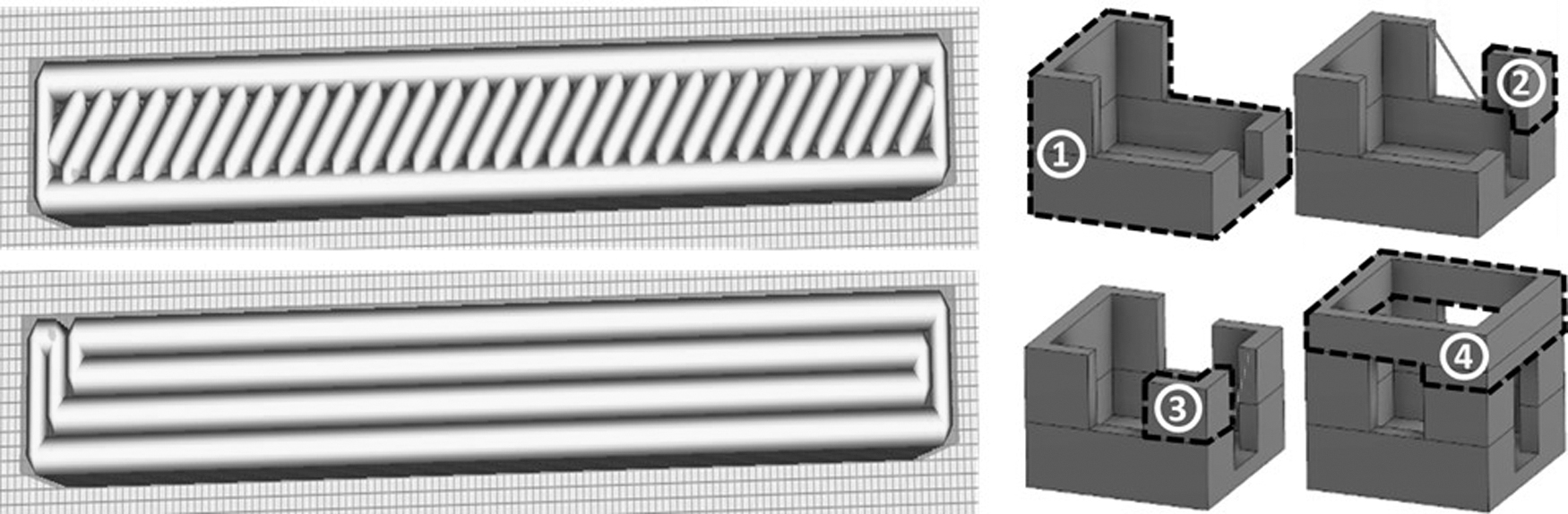
Methods to reduce travel moves in-plane from a discontinuous toolpath (top left) to a continuous toolpath (bottom left), as well as between layered sections (right).
Unfortunately, depending on the geometry of a final designed structure, it may be impossible to completely eliminate travel moves. This most clearly manifests in parts where the layers do not consist of a single enclosed area, but rather several discontinuous “islands” of material. In cases such as this, a travel move must be made from one part of the geometry to the other. However, in this case, it is still possible to minimize the number of travel moves by leveraging the out-of-plane motion capabilities of the robotic arm system. Rather than printing each layer one at a time, the entire structure can instead be considered in 3D, continuous sections. Each of these sections is printed one at a time; on completing a given section, the robotic arm returns to its starting Z-location, where it will then print the next continuous 3D section. By leveraging this approach of printing multiple layers of each section of the non-continuous geometry, travel moves can be reduced to only one travel move per section. As an example of this approach, in Figure 2 (right) a structure was decomposed into four sections so that, by printing each section, travel moves can be reduced to just two.
Though this digital workflow is functional and capable of successfully translating digital designs to a robotic arm toolpath, the need to use multiple data handoffs between programs and incorporate human interpretation for geometry segmenting is inefficient. Ideally, after the STL is created, the design would be transferred to a single piece of software that is capable of segmenting the different geometry sections, ordering and slicing these sections, ensuring a continuous infill toolpath within each one, and transferring it to a readable file for the robotic arm. Such a streamlined approach is essential to achieving the vision of an autonomous, deployable construction solution, and it is thus a priority for future development efforts.
Overcoming system limitations
One of the most significant drawbacks of a robotic arm is in its limited reach. Although conventional gantry systems have been demonstrated to be capable of scaling to construction-size structures, 4 achieving similar deposition sizes with robotic arm systems is challenging, particularly when using commercially available industrial robots. However, there are potential variations to a standard robotic platform that could potentially expand the achievable build volume. This includes the introduction of additional external axes that the robotic arm could move along (i.e., a 7-degree of freedom system) or strategic mounting of the robotic arm along a wall or ceiling, instead of placing it upright on the ground. Unfortunately, these modifications are not necessarily compatible with the authors' vision of agile, deployable construction in remote environments. The introduction of additional guiding rails would significantly increase the size of the package during transport and complicate later assembly, whereas varying the mounting position of the arm would require an advanced knowledge of secondary structures already available on-site for mounting.
To address this limitation, the robotic arm used in this study was strategically modified to increase the achievable build volume. Specifically, while the nozzle is held in a vertical orientation during the printing process, not all the robotic arm axes are being used to their full potential. Specifically, the fourth and sixth axes do not play a major role in the printing process when the nozzle maintains a constant orientation. Exploiting this, an extension was designed to be controlled by the unused axes, with which it becomes possible to print significantly larger structures than were previously possible.
In the case of the system used in this study, the extension added to the robotic arm expands the printing volume in both the XY plane and the Z-direction. By adding the extension arm perpendicular to the sixth axis, the reach in the XY plane is increased. By using a 0° angle on the sixth axis, the robot's reach in the X direction is increased by the length of the extension. Conversely, by using an axis angle above 90°, the nozzle can also reach closer to the robot. By using the fourth axis, the reach of the robot can be extended in the Z-direction. Adding an extension parallel to the sixth axis allows the robot to reach farther down than in its default state. While the fourth axis is at 0°, or in the down position as shown in Figure 3, the robot reaches down the length of the Z extension. When the fourth axis is at 180°, as in Figure 3 in the up position, the robot reaches up the distance of the Z extension. This maneuver requires the nozzle itself to be rotated 180°, to keep the direction of extrusion downward. In doing so, this extends the print volume height by double the length of the extension in the Z direction. However, this enables the robotic arm to reach down below its base. This requires the robotic arm to be raised by a height at least equal to the height of the Z-extension, unless one wishes to print below ground level. By combining both the XY-extension and the Z-extension methods, a build volume can be achieved at a scale far beyond the standard reach of the robot. The full extension setup as implemented can be seen in Figure 3.
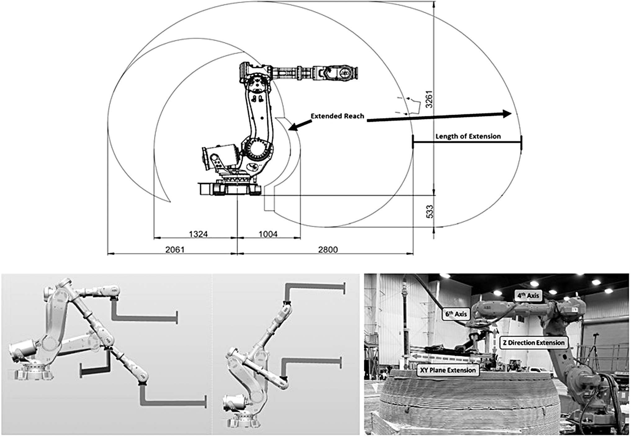
The extended reach of the robot when using the sixth axis to extend the reach in the XY plane (top, all units in mm), the extension in both the down position and up position (bottom left), and the final implemented version on the printing system (bottom right).
The use of extensions does come with limitations. For example, they sacrifice much of the freedom of nozzle orientation, as well as the XY plane reach when the fourth axis is in its 180° position. When using the XY plane extension, a much larger robot movement is required to angle the nozzle forward and backward. This can cause such maneuvers to be out of reach of the robot or may cause it to collide with the printed structure. As discussed, when printing with the flipped fourth axis, the base of the extension is below the extrusion point of the nozzle. This can cause a collision when the cross-section of the print is longer than the length of the XY plane extension. Ultimately, the design of the printed structure must take these limitations into consideration to ensure a successfully built structure. These limitations may be addressed in future iterations of the extension system. For example, an adjustable, telescoping extension would allow for an increased maximum build volume, while also being able to return the robotic arm to a near-default state when retracted.
Leveraging system opportunities
Although the inclusion of extensions can help overcome the limitations associated with the robotic arm's reach, there are also unique design and construction opportunities that present themselves when using a robotic-arm system. For example, a robotic arm can help support the use of in situ embedding in concrete AM. This is a crucial opportunity, since, in typical concrete construction, there are often many prefabricated components that are embedded to increase the strength of the built material as well as add more functionality to the manufactured structure. For example, the tensile strength of normal-weight concrete in flexure is 10–15% of concrete's compressive strength. This means that, although concrete is strong in compression, it is unsafe to use concrete alone under significant tensile loading. As a result, modern concrete construction relies on the use of reinforcement, such as rebar, since, without it, concrete can crack and crumble. 8 Similarly, in end-use construction, there are often windows, electrical wiring, plumbing, and various other components that are necessary to create a livable habitat. Conventional concrete construction requires these components to be manually installed after the concrete cures, which often involves cutting the final concrete structure to place the prefabricated components.
When using a robotic arm to additively manufacture concrete structures, reinforcement and multifunctional prefabricated components can be directly incorporated during the printing process by leveraging existing processes demonstrated in standard-scale AM systems. 33 Due to the layer-by-layer nature of the AM process, every point in the structure is externally accessible at some point during the manufacturing process. This enables designers to pre-define cavities in the designed structure before printing. Then, when the top of the cavity is reached, the printing process is paused and a secondary, foreign object can be embedded in the cavity before printing resumes. 34 The embedding approach can enable complex, multifunctional structures that require no post-print assembly,35–38 which is highly relevant for printed habitats that may need to incorporate reinforcement, windows, electrical wiring, or plumbing.
This is further enabled by the flexibility of the robot's end-effector. By either adding a tool change to the robot, or by integrating a multi-process tool to the robotic arm, it can gain the ability to lay the necessary reinforcement (e.g., rebar) as well as the concrete. This can eliminate the time-consuming process of assembling the reinforcement before pouring the concrete in conventional construction. Similarly, a tool change or second robotic arm can be used to grip and place larger, more complex prefabricated items within the concrete structure during printing. This requires the designer to incorporate a cavity to accept the foreign component in the digital model of the desired concrete geometry. An example of this technique being used in practice is presented in relation to the habitat case study presented in the System Application: Sub-Scale Habitat section.
Results and Discussion: Case Studies
One of the primary motivators behind the AM system in this article was participation in NASA's Centennial Challenge: 3D-Printed Habitat Challenge. 39 This challenge incentivized the development of technology to create habitats on the surface of Mars and laid out increasingly complex tasks to print different aspects related to making such a habitat. These tasks ranged from small cylinders and beams for material testing purposes up to complex geometries with overhangs and embedded objects.
All tasks had to be demonstrated with the high level of autonomy required to support extraterrestrial construction. Despite the Martian context of the NASA Challenge, the lessons learned in concrete AM are readily transferrable to terrestrial applications. To that end, the following subsections detail the use of the proposed concrete AM system to realize two case studies: a dome and a sub-scale habitat.
System application: dome
After completing earlier structure characterization tasks (omitted from this article due to the simplicity of the printed geometries 39 ), the first significant test of the proposed robotic arm concrete AM system was to create a three-pronged hollow dome with a diameter of 1.5 m and a height of 0.5 m, a geometry defined by the NASA challenge. This geometry, seen in Figure 4, combined a much larger scale as compared with previous tasks along with the challenge of printing three separate columns that combine into one horizontal overhang.
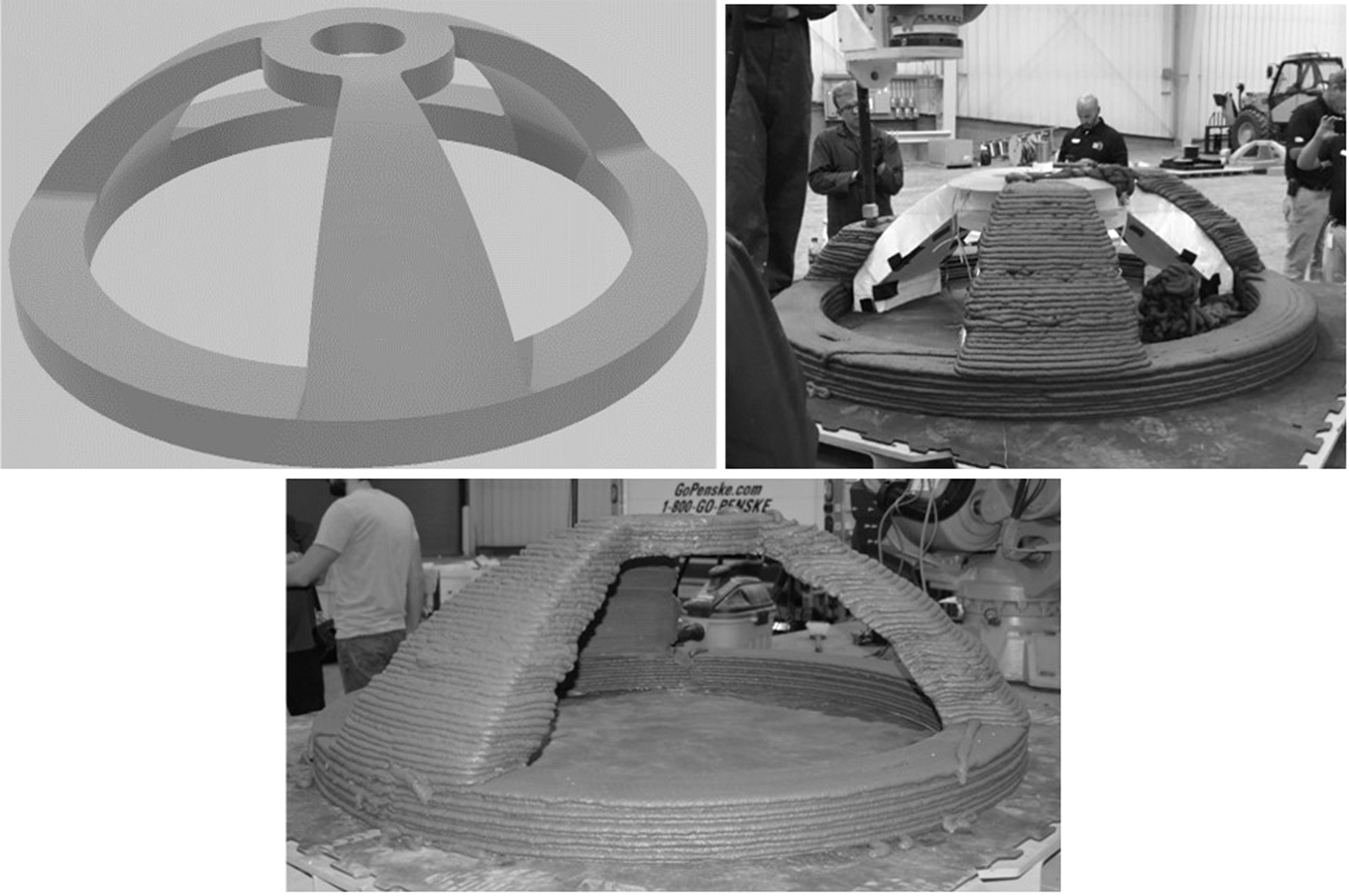
Target dome geometry (top left), printed case study in progress (top right), and the final printed dome structure with support removed (bottom).
The printing was done by using the ABB IRB6640 six-axis robotic arm and the m-tec Duo Mix 2000 mixer–pump connected through a 1″ hydraulic nozzle as described in the Materials and Methods: Design of the AM System section. This allowed for continuous mixing of the dry material from a silo with water, which was then immediately pumped through the hose. All the dry ingredients were mixed in the hopper such that only water needed to be added. This meant that the material started the setting process immediately. The material for this task (MarsCrete, as detailed earlier in the Materials and Methods: Design of the AM System section) was designed to set rapidly so that the printed layers would be able to support subsequent layers without deforming. The accelerants generated an exothermic (heating) response in the material within the pumping subsystem, which required cooling via dry ice around the extrusion piping to keep the material from curing before deposition, a problem that would not exist on Mars due to the low temperatures on the surface of the planet.
As the geometry for this case study was not modifiable, there were two specific challenges that needed to be overcome. The first was the horizontal overhanging disk at the top of the structure. For conventional AM techniques, perfectly horizontal surfaces such as this will require a support scaffolding to be printed underneath them. Although this may take the form of breakaway or soluble support material for more traditional polymer extrusion, concrete scaffolding cannot be easily removed without damaging the final structure. To maintain a high level of autonomy, a separate, secondary support structure (seen in Figure 4) was developed that could be placed, printed on, and then removed by using the robotic arm itself. The arm was fitted with a secondary tool to remove the support structure by pulling it through the gap between two pillars. It should be noted that, although this approach was successful for the dome case study, in the case of a habitat being built in a remote environment, the removal of any support structure will further complicate the system.
The second challenge that needed to be overcome was the frequency of travel moves associated with printing the three pillars of the dome. As mentioned in the Digital Path Planning section, due to challenges with starting and stopping the extrusion of concrete in the system, the number of travel moves for the print needed to be minimized as much as possible. However, if a traditional planar toolpath planning approach were used for this geometry, the result would be two required travel moves for each layer in the midsection of the dome, resulting in significant wasted material and poor geometric accuracy. To address this, the dome was divided into three sections, which could each be printed continuously. This was done by printing the initial bottom ring first followed immediately by one of the three arms by using one continuous path. After the first arm was finished, one travel move was performed to the second arm, then again to the third arm, where the path then transitioned continuously to the final horizontal ring at the top of the structure. This approach results in only two mandatory travel moves in the entirety of the part. Figure 4 shows this approach; in the image, the robotic arm is printing the third and final arm after already completing the base and the two other arms; the final dome structure is also shown in Figure 4. In the end, the final, fully printed dome required 6.2 h of build time, at a print speed of 169 mm/s. This resulted in a material deposition toolpath that was 3782 m long throughout the entirety of the structure.
System application: sub-scale habitat
After completing the dome geometry, the next task centered on the creation of a sub-scale habitat intended to challenge the system's ability to manufacture significantly larger and more complex structures. In this case, the structure was to be a 1/3 scale model of habitat with a minimum of 93 m2 of floor area with a ceiling height of at least 2.25 m. As opposed to the case study presented in the System Application: Dome section, this task allowed the research team the opportunity to specifically design a habitat that exploited the capabilities of the printing system and material. To this end, the final habitat design included (1) relatively simple, circular cross-sections that could be easily planned and executed by using the toolpath approach in the Digital Path Planning section and (2) a conical roof design to avoid the need for a support structure to hold up the roof. Based on preliminary testing, it was found that the self-supporting angle necessary for the conical roof was ∼65° from horizontal; this self-supporting angle, along with the required floor area and the reach of the robotic arm, dictated the height of the final structure. The rooms of the habitat consisted of two main cylindrical sections connected by a shorter central segment to allow for occupant movement between them. The resulting structure stood 3.7 m tall with a maximum width of 4.7 m, as seen in Figure 5. To account for the larger size of this structure, when compared with the dome geometry, the overall build volume needed to be expanded by using the extension arm discussed in the Overcoming System Limitations section.
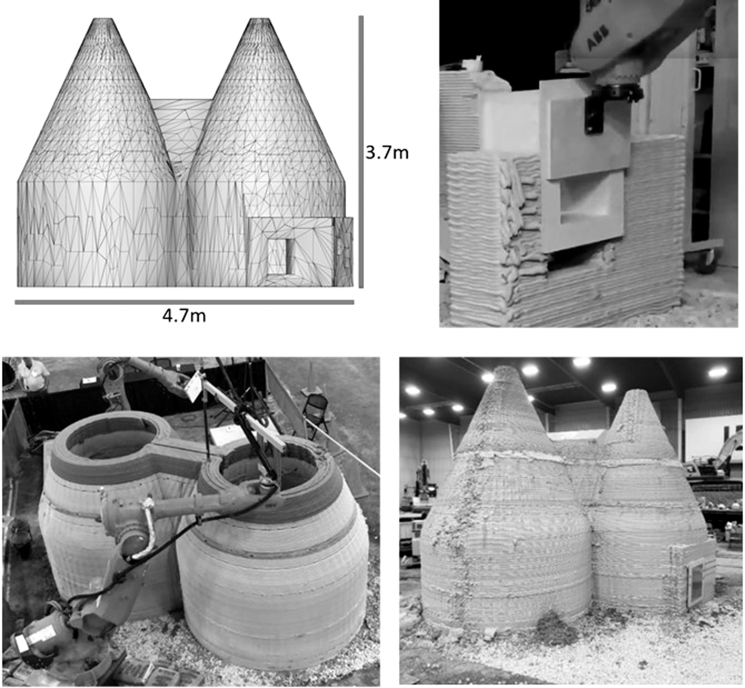
Target habitat geometry (top left), embedding of access hatch (top right), subscale habitat in mid-construction (bottom left), and final printed case study (bottom right).
It should be noted that, due to material supply challenges in the production of MarsCrete (as previously discussed in the Materials and Methods: Design of the AM System section), a Portland cement-based mix was chosen to act as a type of functional simulant for the creation of this subscale habitat. The final subscale habitat structure was anticipated to require 13.2 h of build time, at a print speed of 400 mm/s, which would further result in the use of ∼7.7 m3 of build material. However, due to errors during the build process, which required system pauses and restarts resulting in time and material loss, the final build time was 17.2 h, with 9.5 m3 of consumed material. It should be noted that, in Figure 5, as series of discontinuities can be seen traveling vertically along the cylindrical wall and the conical roof; these artifacts are caused by over-extrusion of build material as perimeters are completed. In future work, these seams can ideally be reduced or eliminated through the introduction of a method to precisely start and stop the flow of material in the system.
Penetrations were an additional requirement of the printed habitat, which included two hatches and a circular window to be set into the structure during printing. To accomplish this, a second robotic arm (ABB IRB 6600 2.8 m) was introduced to work in concert with the primary printing arm. During the design phase, cavities were included in the walls of the habitat so that wooden frames representing the penetrations could be embedded during printing. The secondary robotic arm was programed to pick up each wooden frame from a specific designated point and then place it into the appropriate cavity. It was crucial that the upper surface of each frame be flush with the concrete layer at the top of each cavity so that fresh concrete could be deposited on top of the frame without damaging the extruder or causing defects in the printed structure. Although the second robot was programed specifically to place the windows where they were needed, dimensional tolerances still led to challenges; one penetration was successfully placed, but geometric inaccuracies caused by vibrations in the system and increased deformation of the deposited material under the weight of layers on the top prevented the other two windows from being inserted entirely autonomously.
Conclusions
This work offers a proof-of-concept to validate the use of a robotic-arm concrete AM system to produce architectural-scale habitats. Though using a robotic arm base may initially seem limited due to its reach, yet it is possible to overcome these deficiencies through system modifications such as the extensions used in this research. These system modifications, along with careful consideration of the material deposition path and the inclusion of embedded components, help establish the proposed system as a viable method for additive construction. This viability was demonstrated through two case studies conducted through the context of NASA's Centennial Challenge: 3D-Printed Habitat Challenge: a dome structure and a one-third-scale habitat. These system solutions have created a steppingstone for future work by making a working system within a lab context. Although the system has been demonstrated to be capable of being transported to a specified printing site, the setup currently requires more human intervention than would ultimately be desired in a remote environment. In addition, the current robotic arm system is limited in its ability to construct a full-scale habitat based on the design in this work. Increasing the scale of the robotic arm, or establishing cooperation between multiple robotic arms, will be needed to eventually achieve the desired full-scale habitat.
To further improve the quality of manufactured structures, future research will seek to expand the capabilities of the robotic arm printing system, while also introducing additional elements to increase the system's robustness. Potential opportunities to increase the robotic system's capabilities include (1) methods to successfully start and stop the flow of material within the system, (2) implementing an adaptable extension arm that can change length depending on the needs of the structure, and (3) introducing additional robots working collaboratively to increase the available build volume and build speed. Robustness of the system could be improved through (1) the introduction of sensing and feedback measures to adapt printing on-the-fly in response to changing conditions; (2) leveraging advanced optimization methods to better plan both the continuous infill toolpath and the printing order of different structure segments; and (3) streamlining the digital workflow needed to design the concrete structures, ensure their manufacturability, and convert them to a format that is suitable for robotic arm deposition.
Footnotes
Acknowledgments
The authors express their gratitude to Dr. Ali Memari, Dr. Aleksandra Radlińska, and Mr. Jamie Heilman for their valuable insights and contributions to this research. An earlier version of this work was published as “Large-Scale Additive Manufacturing of Concrete Using a 6-Axis Robotic Arm for Autonomous Habitat Construction” at the 2019 Solid Freeform Fabrication Symposium in Austin, TX.
Author Disclosure Statement
The authors declare no conflict of interest.
Funding Information
This research was financially sponsored by The Raymond A. Bowers Program for Excellence in Design and Construction of the Built Environment, The Pennsylvania State University, Autodesk, Inc.®, and Golf Concrete Technology (GCT).