
Abstract
As the most commonly used additive manufacturing technology, fused deposition modeling (FDM) still faces some technical issues caused by temperature change-induced unsteady thermal stress and warping. These issues can further lead to the deformation of printed parts and even terminate the printing process. In response to these issues, this article established a numerical model of temperature field and thermal stress field for FDM by finite element modeling and “birth–death element” technique to predict the deformation of the part. What makes sense in this process is that the logic of elements sort based on ANSYS Parametric Design Language (APDL) was proposed to sort the meshed elements, which was aimed to perform FDM simulation quickly on the model. In this work, the effects of the sheets shape and infill line directions (ILDs) on the distortion during FDM were simulated and verified. From the analysis of stress field and deformation nephogram, the simulation results indicated that ILD had greater effects on the distortion. Moreover, the sheet warping became most serious when the ILD was aligned with the diagonal of the sheet. The simulation results matched well with the experimental results. Thus, the proposed method in this work can be used to optimize the printing parameters for FDM process.
Introduction
Additive manufacturing (AM), also known as three-dimensional (3D) printing technology, has been considered the most promising manufacturing technology. In 3D printing, computer-aided design (CAD) models are created and converted into the data of each layer, and corresponding parts and prototypes with complex shapes are constructed by depositing materials in a layer-by-layer manner. 3D printing technology has many great advantages over the traditional fabrication procedures, such as high customization, rapid prototyping, and low material cost. 1 Among seven 3D printing technologies, fused deposition modeling (FDM) (also known as fused filament fabrication) is most popular and widely used for rapid manufacturing of complex parts. 2 In FDM, solid polymer filament is fed into a printhead via a gearwheel. In the printhead, heating elements are utilized to increase the temperature to above the melting temperature of the polymer and melt the polymer filament that is extruded through a dispensing nozzle to form a continuous cylindrical filament. Since the ambient temperature or the platform temperature is much lower than the melting temperature, solidification rapidly happens to cause the transition of the filament states from molten to solid, 3 as shown in Figure 1. Due to its easy implementation, low cost, and wide range of printable materials, FDM has been widely used for various applications, such as medicine,4,5 electronic devices, 6 construction industry, automobile manufacturing, and aviation.7,8 Currently, the investigations of FDM focus on the build materials, especially composite polymer materials. The main matrix polymers to prepare composite polymer filament include acrylonitrile butadiene styrene (ABS), polylactic acid (PLA), polyamide, polypropylene (PP), polyethylene (PE), and other thermoplastic polymers.9,10 ABS, as a thermoplastic polymer that is widely used in various fields such as electronics, automobiles, and other industries, is also a common plastic filament that is fed into an extrusion nozzle head and heated for preparing parts. The initial coefficient of thermal expansion of the neat ABS reaches 6 × 10⁻⁵/K, which is higher than most plastic filament for FDM process. With the mechanical property of ABS mentioned above, unsteady thermal stress of part would be created by inhomogeneous temperature field when ABS filament cooling in FDM process and unsteady thermal stress would more obviously lead to the warping or distortion of parts than other plastic filament. In conclusion, ABS as the filament in this study is meaningful and representative.11–16

Schematic of FDM process and the main components in FDM-based 3D printer. 17 3D, three-dimensional; FDM, fused deposition modeling.
During FDM process, build material experiences thermal expansion due to the high working temperature in the printhead as well as cooling contraction due to the low ambient temperature outside the printhead. As a result, different deposition times of the build materials lead to the generation of large thermal gradient in the printed parts. This thermal gradient further results in the different shrinkages between each layer, which causes the distortion of the final parts. 18 The thermal shrinkage of the build materials can generally result in two types of deflects: interlayer deformation and the intralayer deflection. For the parts printed by raster filling trajectory, the interlayer deformation is more pronounced than the intralayer deflection. Thus, warping rather than delamination is the main deformation of the printed parts. 19
How to overcome the distortion of the printed parts becomes a major technical issue that inhibits the wide application of FDM technology. Many scholars and researchers have made great contributions for figuring out this issue.20,21 For example, using masking tape is a common method to prevent warping in FDM since the adhesion between parts and masking tape can prevent warping during printing. Another popular strategy is to compensate the thermal shrinkage of the printed parts by designing the geometries larger than the desired sizes. Besides, adding line segments around the parts is also a promising method to constrain the thermal shrinkage of the parts. 22 Guerrero-de-Mier et al. 23 proposed that stacking section length was one of the major factors affecting warping among other factors. Their work was to develop splitting pieces in bricks that limit the maximum value of stacking section length, which reduced the warping deformation. Sardinha et al. 24 proposed that residual thermal stress was the main factor causing the warping and the residual stress could be released through the ironing process. Their results also showed that the warping was increasingly reduced as the ironing layer approached the heated bed. Zhang and Moon 25 established a novel thermal annealing methodology to release residual thermal stress. Their results showed that all the annealed samples expanded in the layering direction, which indicated a thermal stress relief.
Except aforementioned strategies, optimizing the printing parameters is another direction for solving this distortion problem. Some leading commercial simulation software has been used to predict the deformation of the parts during 3D printing. For example, Cattenone et al. 26 established a finite element analysis framework for simulating the melt deposition molding and predicting distortion of model. Based on a series of simulation data comparison, it was found that time step and mesh generation strategy had the great effects on the simulation results, and the correctness of the theoretical model was verified by the experiments. However, the shape of the model was not considered a factor affecting deformation in this study. Compton et al. 27 developed a one-dimensional finite difference thermoplastic model to simulate the process of large-scale AM. They found that the temperature of the top layer of the 3D printed part should be above the glass transition temperature of the build material to prevent the matrix from cracking and delamination. Simultaneously, the temperature of the printing chamber significantly affected the distortion of the printed part. Zhang et al. 28 simulated FDM using a 3D finite element simulation method, which combined the additional characteristics of the material deposition process and thermal–mechanical phenomena. This method showed that the arch bridge warping phenomenon of the part was caused by the asymmetrical stress distribution. In the above research, the proposed simulation methods have solved the problem in a targeted manner. Combining previous work, we proposed a unique logic for element sort to make FDM simulation more convenient.
In this study, we presented a comprehensive finite element simulation-based thermal–structural coupling framework for predicting the warping phenomenon in FDM. Furthermore, we would detail the logic of elements sort in the simulation script. Herein, a commercial software was used to simulate and analyze the printing process by using the “birth–death element” technique. 29 The thermal evolution of the part during printing and the distortion caused by the uneven thermal shrinkage were analyzed. At the same time, it was doubted whether infill line direction (ILD) [45°, −45°], which was parameter commonly used in AM with high mechanical strength, 30 was also the best for FDM process. Thus, ILDs and shapes of model were considered research variables in this study. The significance of this study is to provide a simulation framework, which can easily and quickly predict the thermal evolution and distortion in FDM to achieve the optimal printing parameters and guide the 3D printing practice without wasting materials.
Simulations and Verification
The overall framework of this research is illustrated in Figure 2, which had two sections: FDM 3D printing experiment and FDM simulation. In the experiment, first, a 3D model was established through a CAD software (SCDM). Then, the triangle mesh file (STL file), the file format recognized by slicing software, was generated. After that, g-code file was created by a slicing software (Ultimaker Cura 3.6.0), which was used in a FDM printer to print the part. For the simulation, ANSYS parametric design language (APDL) was used to mimic the FDM printing process. In this study, a nonlinear transient analysis was utilized to simulate the model, in which the build material was added up over time. Thus, a “birth–death element” technique in APDL was adopted in FDM finite element analysis to kill selected elements and reactivate elements according to the deposition path. Herein, to reduce the calculation time, we selected a two-step method to conduct the thermal–structural coupling analysis. In the first step, a thermal analysis was performed on the model, and in the second step, the result from the thermal analysis was applied as a load to conduct a structural analysis of the model to obtain the stress–strain relationship.

Flowchart of the research process.
Birth–death element technique
In these cases, birth–death element technique is used to kill or reactivate selected element. To achieve the “element death” effect, the program does not actually remove “killed” elements. Instead, it deactivates them by multiplying their stiffness by a severe reduction factor (default value is 1.0E-6). Element loads associated with deactivated elements are zeroed out of the load vector. However, they still appear in element-load lists. Similarly, they are not added to the model actually, when elements are “born.” They are reactivated. Based on the function of the birth–death element option, this technique can be applied to simulate the process of material accumulation over time.31–34
Logic of elements sort
In simulation, a script based on APDL was developed. Unlike some sophisticated graphical user interfaces, the proposed script can easily be used to simulate FDM because of elements sort, allowing users to read and modify conveniently. The contents of the script mainly included the setting of the thermal and mechanical properties of the build material, model building and meshing, element sorting, and loading and solving, as detailed in the Supplementary Data.
During simulation, each element label was automatically assigned by the software. Therefore, it was necessary to sort the elements in the FDM area. The activation of the elements can be better controlled by arranging the elements based on the printing path. The element sort section in the script is shown in Figure 3. From the flowchart, it was found that the sort section was implemented by using APDL module to traverse the element over and over again through do-loops. There were two main array creations and two data comparisons in each loop. The function of the array was to store the number and coordinate information of the element and further select the element by comparing the data in the array. In the simulation software, the Y-component of the coordinate was regarded as the elevation, and the X- and Z-components were the abscissa and ordinate, respectively. In the first creation of the array, the coordinates of the element centroid as well as the element number were written into the corresponding array. According to the deposition order of the raster filling trajectory, the Y-components of the element coordinates were compared to determine the elements at the bottom. Then, the coordinates of the elements at the same bottom were compared to get the element with the smallest Z-component. In the second creation of the array, the elements in the same row were selected and written into the array. Thus, a row of sorted elements was obtained and written into the sequential array that was eliminated in the next round of the loop. The do-loop was not stopped until the sequential array was full. Different ILDs of the model can be realized by establishing a local coordinate system. The elements sort was suitable for simulating any models in FDM.

Flowchart of the element sort section.
Material properties and parameters
In this study, we aimed to simulate the parts made from ABS filaments (ABS 757; Guangzhou Flythinking Intelligent Technology Co., Ltd., China), which was a typical thermoplastic polymer. Material property values used for the following analyses were provided by company that provides ABS filament. Although the material properties of ABS change with temperature, the material parameters in this work were simplified as constants. The thermal conductivity and the thermal expansion coefficient of ABS filament were isotropic. In the cooling process, the material changed from the molten state (viscoelastic polymer melt) to the glass state (solid polymer). But herein, this phase transition-induced enthalpy change was not considered. The printing temperature of simulation was a commonly printing parameter for ABS filament. Since the printing environment was open, ambient temperature was defaulted to room temperature (25°C). The specific thermal conductivity of the masking tape on the building platform was unknown, and the temperature at the bottom of the model deviated greatly from the set value due to the masking tape between the building platform and the model in the simulation, as shown in Supplementary Figure S1. Moreover, in the experiment, the printing environment was open. Most of the building platform and model were exposed to the air. The air had taken away a lot of heat in a short time, causing the temperature at the bottom of the parts to be slightly lower than the set value. According to the above two situations, for convenience, the building temperature was defaulted to room temperature. Thus, the material properties used in the following analysis and the loads required for the simulation are summarized in Table 1.
Input Parameters
Model and ILDs
Herein, we used the script to perform simulations on four different shapes of sheets with five ILDs. The design of the orthogonal simulations is summarized in Table 2. The main purpose of the simulations was to understand the effects of the shape and ILD on the temperature field and model distortion.
The Number of Each Model
ILD, infill line direction.
The dimensions of the four models are shown in Figure 4. In particular, the height of each sheet was 2.4 mm and the area was about 3600 mm2. Since the volumes of these thin sheets were equivalent, the total number of the elements for each sheet after meshing was the same, which made the comparison between different models more meaningful. The ILD referred to the normal direction of the deposition line, which was the angle between the normal line and the X-axis (or Z-axis). As shown in Figure 4e, the ILD of [0, 45] meant that the normal direction of the first layer was aligned with the positive X-axis direction, and the normal direction of the second layer was 45° with the positive X-axis direction. In Figure 4f, the ILD [0, 90] meant that the normal direction of the first layer was consistent with the positive X-axis direction, and the normal direction of the second layer was perpendicular (90°) to the positive X-axis direction. The ILD specified the deposition direction of high-temperature filaments onto the low-temperature solidified layers, which affected the thermal evolution of the parts during FDM-based printing.
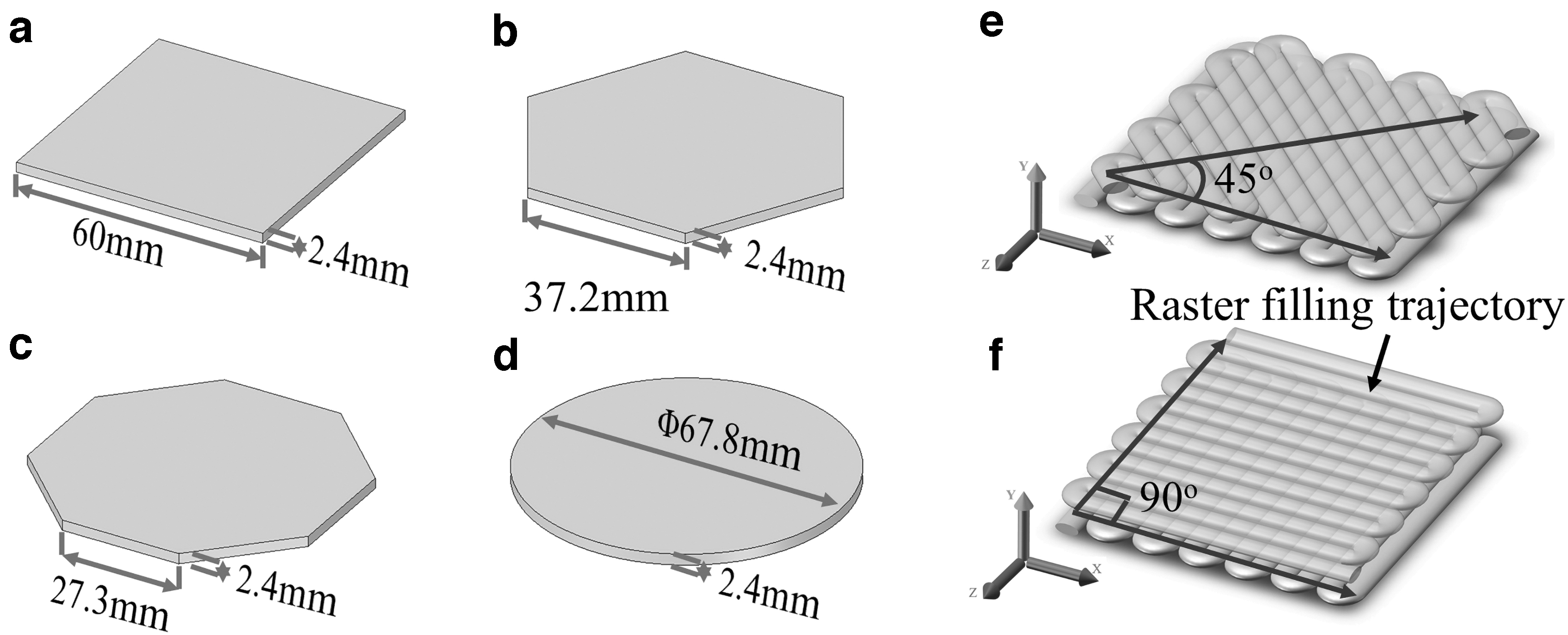
Four sheets with different shapes for simulation:
Meshing strategy
The element types, which have special features of birth and death element and are suitable for thermal analysis, include SOLID70, SOLID87, and SOLID90. Among them, SOLID87 is well suited to model irregular meshes because it is a tetrahedron element type. However, the finite element model in this research is relatively regular and the hexahedral element type will be used to model meshes to improve the modeling accuracy and reduce the calculated cost. Compared with SOLID70, SOLID90, as a higher order version, involves intensive computations. So, SOLID87 and SOLID90 are not suitable for this research. To study the stress field, thermal analysis element type needs to be converted into a structural analysis element type. Here, SOLID70 element is converted to the SOLID185 element, which is used for 3D modeling of solid structures.35–37 In thermal analysis of this article, SOLID70 was used as the analysis element, 38 whereas in structural analysis, the element type was changed to SOLID185. Both these element types were able to be divided into hexahedral elements, prismatic elements, and tetrahedral elements. The script in this work did not constrain the shape and the division of the grid. However, for improving the accuracy of the calculation and the controllability of the number of grids, the hexahedral elements and free division were selected. The global cell size was set as 0.0008 m, which was equivalent to the size of the dispensing nozzle in the verification experiments. Each sheet was divided into six layers with the height of each layer of 0.0004 m, which was also equal to the height of the printed layers of each model in the verification experiments.
Simplification and boundary conditions
Because many factors in FDM can affect the quality of the final prints, some reasonable simplifications were made in this study to emphasize the effects of the key factors as follows39,40: (1) The thermal analysis was performed based on the Fourier law of heat conduction and the law of conservation of energy. (2) Heat radiation and enthalpy change were not considered during the cooling process. (3) The temperature of the extruded filament was the same as the temperature of the heating elements in the printhead, and the initial temperature of the extruded filament was uniform. (4) The solid material followed the Von Mises yield criterion during plastic deformation. (5) The material did not fail in the thermal–structural coupling simulation. (6) There was no adhesion between the parts and the building platform. (7) In the thermal analysis, the heat conduction between the part and the environment was considered the natural thermal convection, the heat conduction between the part and the building platform was considered the thermal convection, and the temperature of the building platform was simplified as the ambient temperature.
Heat conduction methods include heat conduction, heat convection, and heat radiation. In this study, the effects of heat radiation were ignored while the functions of heat conduction and heat convection were considered. SOLID70 was used as an analysis element type, which was a 3D eight-node thermal element with “birth–death element” function. When setting the boundary conditions, the printing temperature was applied to the eight nodes of the element that had just been activated, and the external nodes of the other activated elements were considered to have the natural heat convection with the environment. The bottom surface of the model was in touch with the building platform, and the temperature was set as the constant chamber temperature.
In thermal stress simulation or structural simulation, the element type was switched to a 3D eight-node solid structure element, SOLID185, which was mainly used to construct 3D solid structures with super elasticity, stress toughening, creep, and large deformation capability. To simplify the calculation and facilitate the comparison, the bottom nodes of the first activated element and several surrounding elements were fully and statically restrained. The diagonal position of the constraint was the node in the thermomechanical analysis. Figure 5a illustrates the constraint and node A at the diagonal position. The constraints and analyzed nodes of the regular hexagon and the regular octagon sheets were the same with those of the square sheets. Figure 5b demonstrates the constraint and the node A in the circle sheet. The Y-component of the displacement of the node A was utilized to characterize the extent of the model warping.
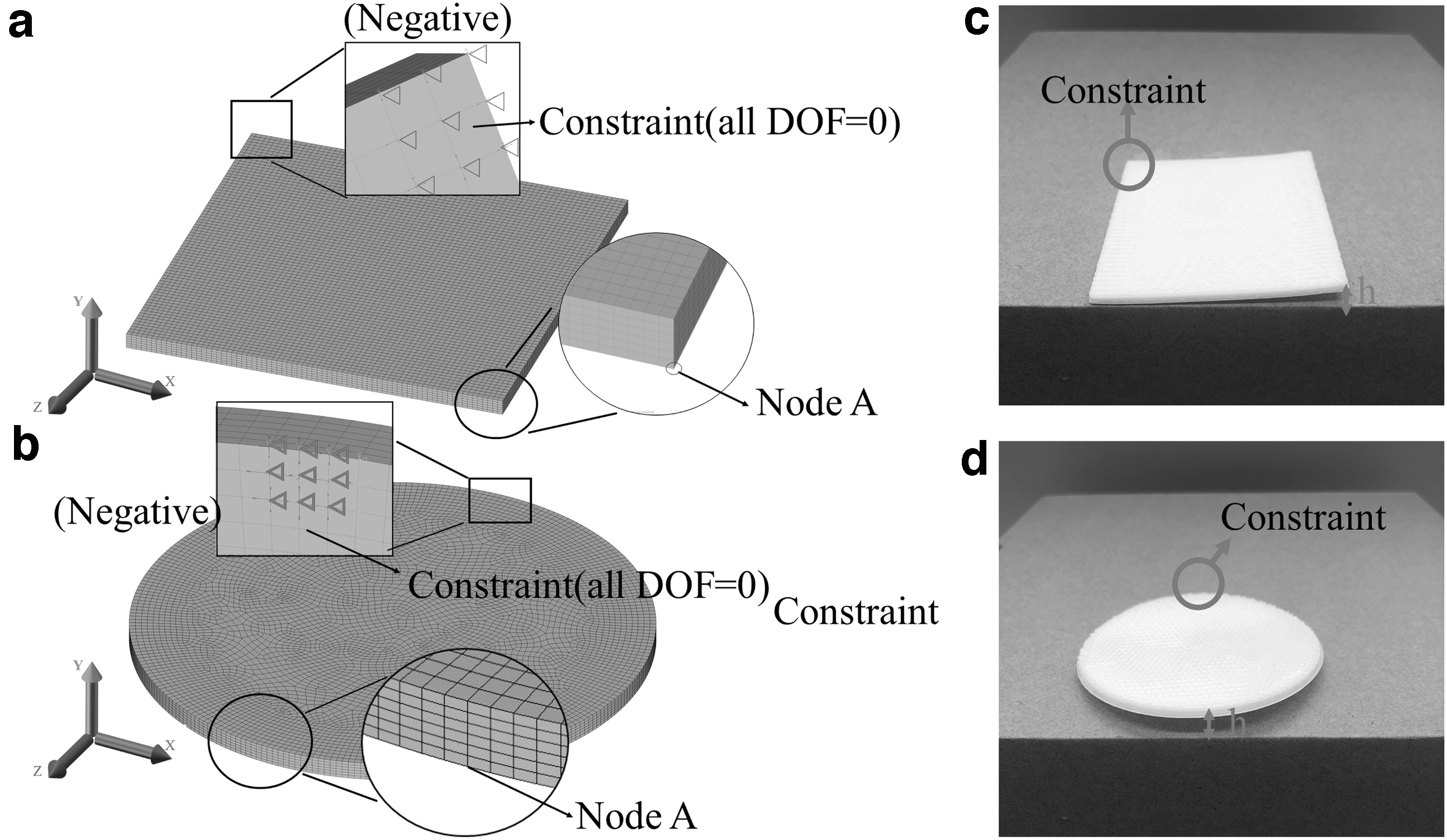
The constraint and node A in
In the simulation, each model had a cooling time of 300 s after printing. Each model had 30,000 to 35,000 load steps, which required a huge amount of memory to save the calculation data of each step. To save the memory, the data were recorded every 6 s and the last data during printing were saved, while the data were saved every 10 s in the cooling process.
Verification experiments
Figure 6 illustrates the FDM-based 3D printer (FS-200; Guangzhou Flythinking Intelligent Technology Co., Ltd.) with a 0.8 mm dispensing nozzle, which was used to print the sheets with different shapes in the verification experiments. Except for the special instructions, the printing parameters used in the verification experiments were consistent with those in the simulations. As shown in Figure 6c, to ensure the success of the model printing, a part of the brim was used for the platform adhesion and the temperature of the building platform was set at 60°C. As shown in Figure 5c and d, the verification experiments used the same method with the method in simulation to quantify the extent of the sheet warping. The parameter h in each figure was equivalent to the Y-component of the displacement in the simulation data. Vernier calipers were used to measure parameter h to indicate the warping of the sheets, and the main error was accidental error.

The exterior
Results and Discussion
Thermal analysis
Figure 7 shows the temperature distribution in each model at the end of printing. It is found that most areas of each model are in a low-temperature state and only a small portion of the entire area being printed is at high temperature. Since both the environment temperature and the building platform temperature were set as 25°C, the large temperature difference between the printing temperature (240°C) and the ambient temperature resulted in a higher cooling rate. In addition, as shown in Figure 7, the temperature distributed uniformly along the filling trace direction. 39 As a result, it is concluded that the temperature field from the simulation is consistent with that from the printing process.
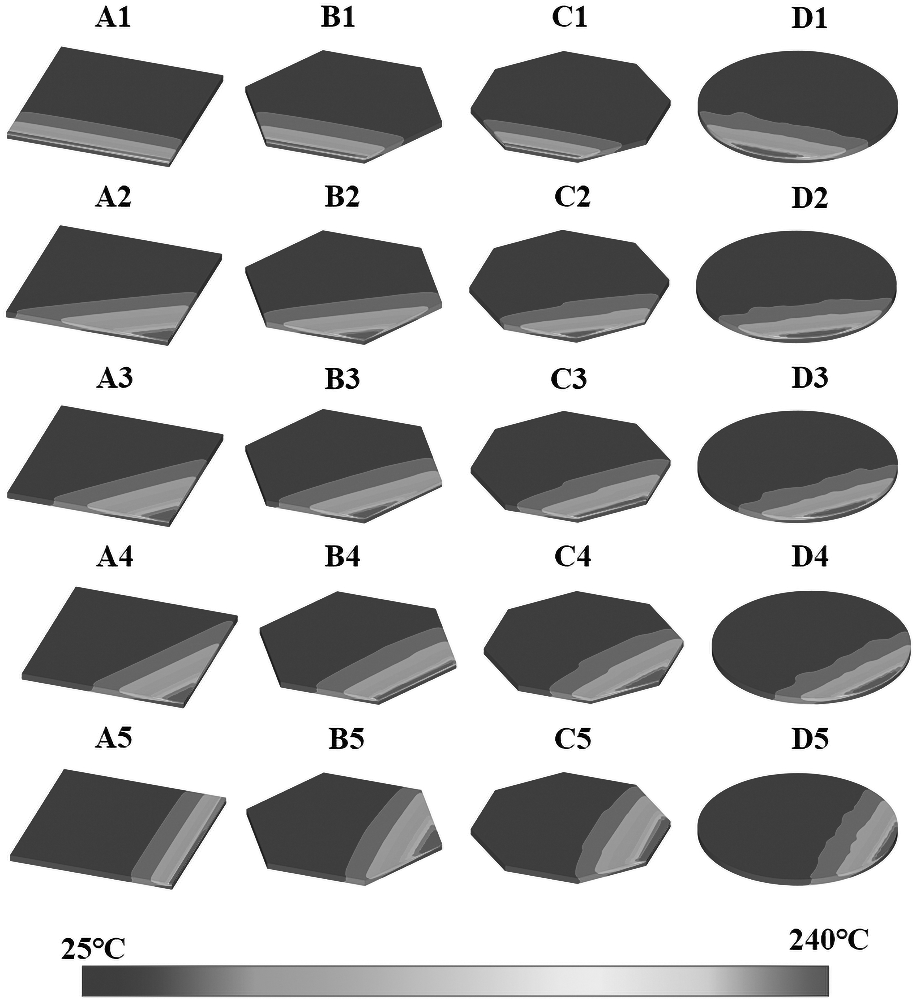
Temperature distribution of each model at the end of printing.
To further analyze the temperature distribution during the whole printing process, node A was selected for a detailed study since it was the last deposition position in the first layer, which needed to be significantly characterized. Figure 8 illustrates temperature change over time at node A of A1 model. The initial temperature was 240°C, which was equivalent to the printing temperature. Then, the temperature decreased as the heat source (dispensing nozzle) moved away. When the upper elements were activated, the temperature of node A fluctuated with a decreasing trend and the amplitude of the fluctuation became smaller with the increasing the number of layers. The first and second temperature peaks of node A were 155°C and 122°C, respectively. Both temperature peaks exceeded the glass transition temperature of ABS, 11 indicating that node A merged with the second layer twice during printing. With the increase of layer number, although the temperature of node A fluctuated, it was lower than the glass transition temperature of the build material, making the molecular chains of the filament at a frozen state without heat-driven bonding. 20

The time history diagram of the temperature at node A of the A1 model.
Figure 9 demonstrates the temperature change curve of node A in the four models. Because the numbers of the elements in the four models were slightly different, the cooling time of each shape was also slightly varied. It is found that the five curves for the square sheet presented a high overlap, whereas the curves for the other sheets deviated slightly from each other. However, the first peak in all curves occurred at the temperature above the glass transition temperature of ABS. The results indicated that the ILD had negligible effects on the interlayer adhesion, resulting in the well-bonded models during printing without delamination distortion.
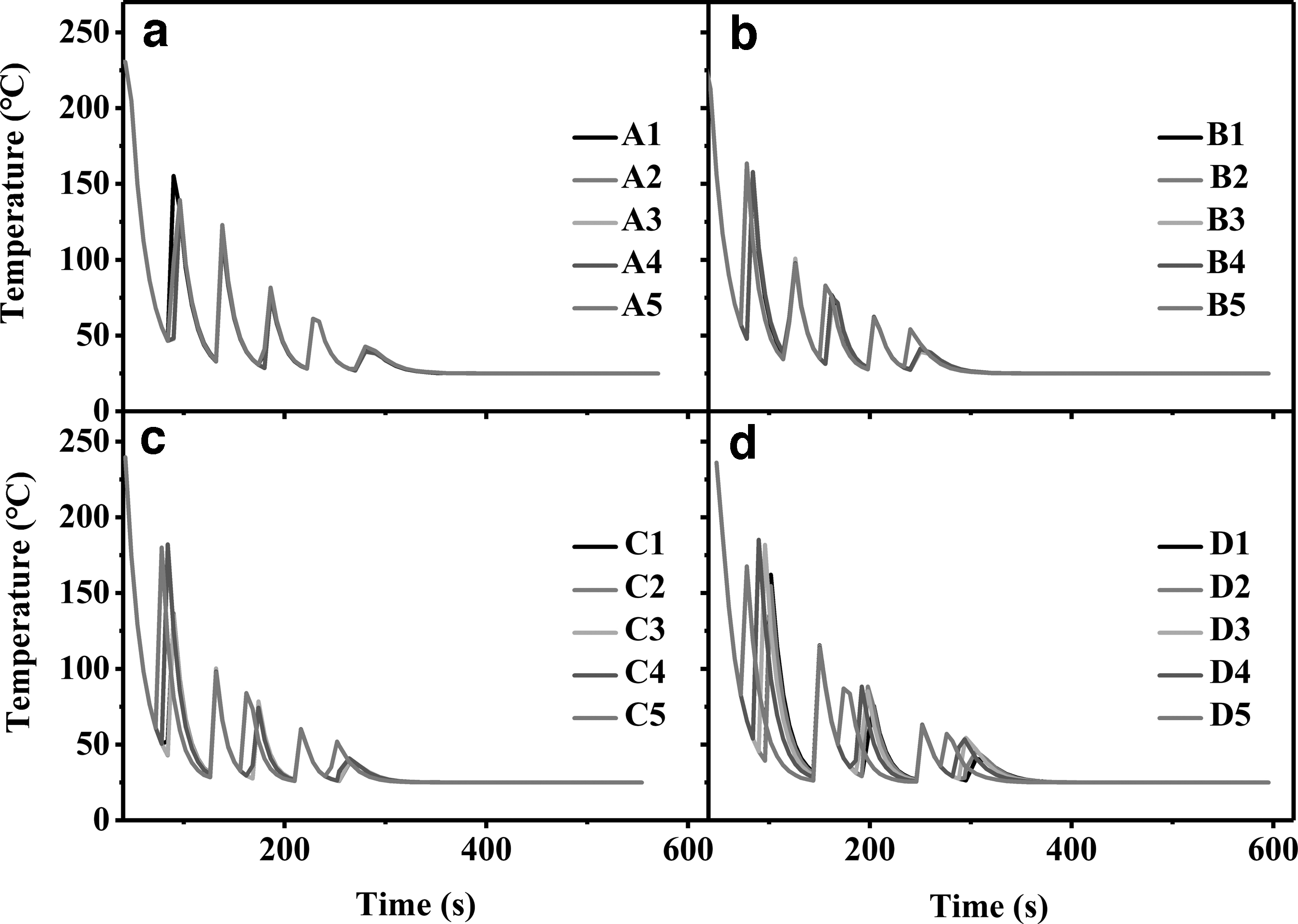
Comparison of the temperature–time curves at node point A for each model:
Structural analysis
In the printing process, the heat generated by the currently deposited filament was transferred to the previous layers, which enabled the previous layers to re-shrink as they cooled down again. In this case, the thermal stresses in the previous layers were changed. 41 Figure 10 shows the Y-component of the stress–time curve for node A in the A1 model. From Figure 10, it is found that the Y-component of the stress fluctuated between negative and positive values. Node A experienced a tensile force along the negative direction of the Y-axis when the Y-component of the stress was negative, whereas underwent a tensile force along the positive direction of the Y-axis when the Y-component was positive. As aforementioned, the direction of the deformation tendency of the part during printing was not fixed but varied based on the temperature distribution. Figure 11 illustrates the Y-component of the displacement curve of node point A in the A1 model over time. It is observed that the displacement of the node A on the Y axis also fluctuated between positive and negative, resulting the arch bridge warping and boat warping during printing. After printing, the temperature of the model gradually stabilized, and the displacement of the node A was 0.7253 mm. This phenomenon was consistent with the analysis, as shown in Figure 10.

The Y-component of the stress over time of node A in the A1 model.
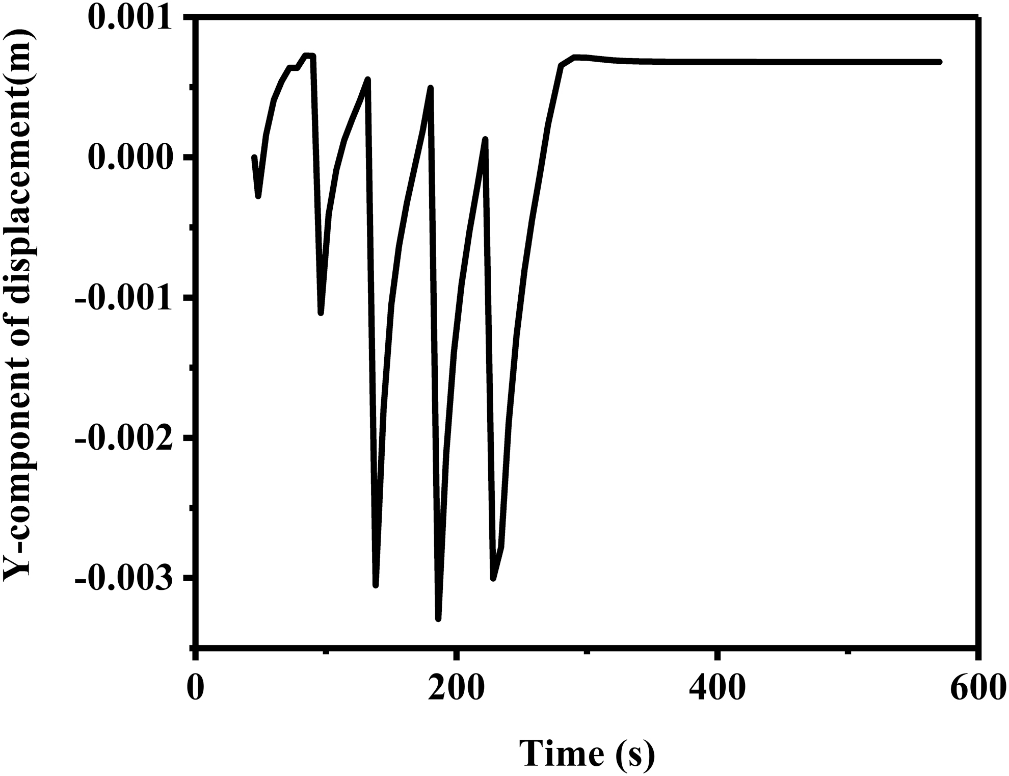
The Y-component of the displacement over time of node A in the A1 model.
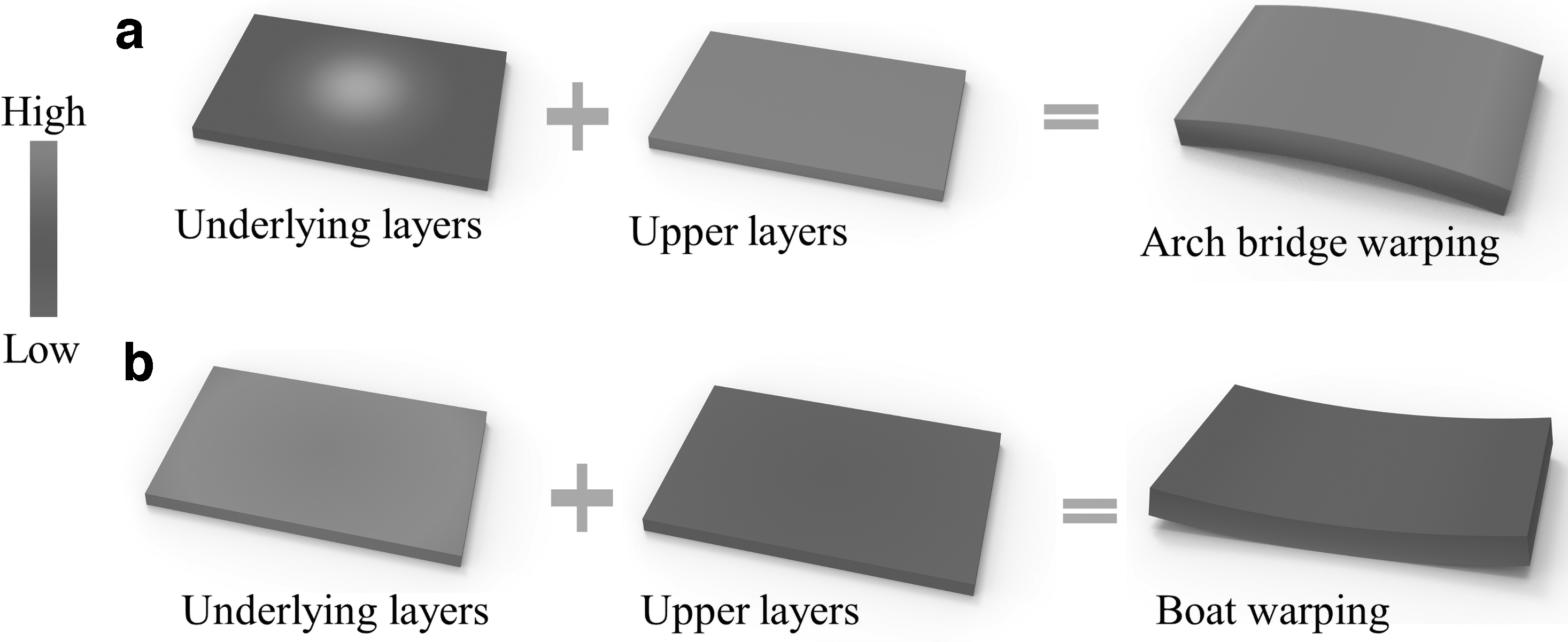
The schematics of the arch bridge warping and boat warping are illustrated in Figure 12 to help understand the two warping mechanisms in 3D printed parts. As shown in Figure 12a, the filaments in the upper layer were just deposited and the heat dissipation time was short. Thus, the temperature was relatively high and the build material was in the state of thermal expansion. In contrast, the build material in the underlying (previous) layer had a long cooling time to reduce the temperature, resulting in the state of thermal contraction. Thus, in this case, the printed parts tended to present an arch bridge warping. As shown in Figure 6c, arch bridge warping has occurred in the FDM process for the failure of the masking tape. However, this situation rarely happened in the real printing process due to the existence of masking tape between parts and building platform. In fact, the build materials in the upper layer were exposed to the environment, but the deposited materials in the underlying layer were in touch with the building platform. As a result, the cooling rate of the upper layer was larger than that of the underlying layer. When the temperature of the upper layer was lower than that of the underlying layer, the shrinkage of the upper layer was more pronounced than that of the underlying layer, resulting in the boat warping phenomenon (Fig. 12b). Because the boat warping started from the corners of a print and the adhesion between the corners and the building platform was not strong enough, this warping generally occurred in the form of edge warping when the bending torque was large during the printing process.
Schematics of
Model comparison
The simulation results indicated that the parts eventually presented the boat warping phenomenon. Supplementary Table S1 lists the maximum displacement in the positive direction of the Y-axis of the node A in each model. In addition, the displacements of the sheets with different shapes during warping are illustrated in Figure 13 to unveil the displacement–shape–ILD relationship. It is observed that the ILD had negligible effects on the warping of the circle sheets and the Y-component displacements of node A in the circle sheets slightly changed in the range of 0.5 to 0.6 mm. In contrast, the ILD significantly affected the warping of the sheets with the other shapes. The warping of the square sheet was most serious when the ILD was [0, 45]. The warping peak of the regular hexagonal sheet appeared when the ILDs were [0, 30] and [0, 90]. Furthermore, as shown in Figure 13, the ILD affected the warping of the octagonal sheet greatly since the number of the elements in the regular octagonal sheet was more than that in the other sheets, resulting in the increase of the manufacturing and cooling time of each layer. Thus, it is concluded that the effects of the ILD are more obvious on the angular shaped sheets. Moreover, the sheet warping becomes most serious when the ILD is aligned with the diagonal of the sheet.
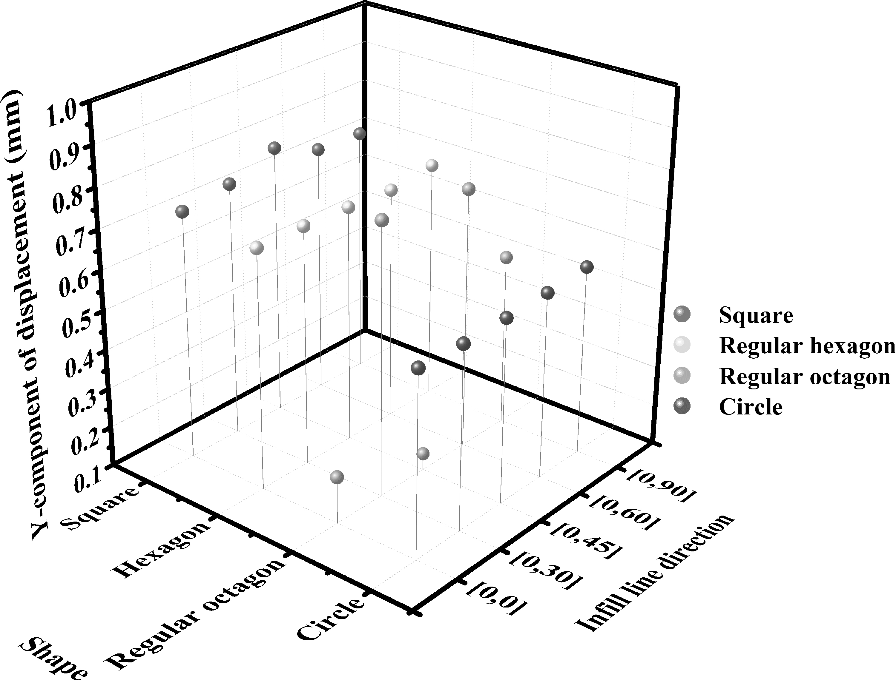
The Y-component of the displacement of node A in each model.
The thermal flux of the last activated element can be used to explain the above phenomenon. After printing, the thermal flux vector sum of the last activated element of the part was able to reflect the cooling speed. It is observed from Supplementary Table S2 and Figure 14 that the last activated element had a high heat flux under a huge temperature difference. The sums of the heat flux vectors of the circle sheets with five ILDs were almost the same, which were basically between 66,000 and 66,500 W/m2. However, for the other shapes, the heat flux vector sum was greatly affected by the ILD. For example, the difference between the maximum and minimum values of the heat flux of the square model reached 4098 W/m2. That is because when the ILD is aligned with the diagonal of the sheet, the printing start line and end line are merged to one point. Thus, the heat preservation capacity of the corner position is relatively weak, enabling the heat flux and the cooling rate to increase during the cooling process. From the perspective of thermal–structural coupling in cooling, the material at the corners is close to uniaxial tension, whereas the material at the interior of part is close to equibiaxial tension, implying that dimensional instability is more at the corners than at the interior of part. 42

The thermal flux vector sum of the last activated element in each model.
Experimental verification
Supplementary Figure S2 and Supplementary Table S3 show the warping and measurement data of the square, regular hexagon, regular octagon, and circle sheets in the 3D printing experiments. It was observed that ILD had negligible effects on the warping of circle sheets but significant impacts on the warping of the square, regular hexagon, and regular octagon sheets. As shown in Figure 15a, the maximum warping occurred at ILD [0, 45] in square sheet, at ILD [0, 30] and ILD [0, 90] in regular hexagon sheet, and at ILD [0, 30] and ILD [0, 60] in regular octagon sheet, which were consistent with the simulation results. It was clear that the sheet warping became most serious when the ILD was aligned with the diagonal of the sheet. As shown in Figure 15a and b, the overall trends of the warping of the sheets in the experiments were basically consistent with the results in the simulation. However, comparing the data in Figure 15a with those in Figure 15b, it was obvious that the warping of sheets was generally between 1 and ∼2 mm in the experiment, whereas in the simulation the warping varies between 0.5 and ∼1 mm. This was because the simulation was carried out in the ideal state, while the experiment was affected by various factors. In the printing process, the slight warping of the parts reduced the deposition of the high temperature filament from the nozzle and the heat conduction of the building platform to the parts, which led to that the residual thermal stress could not be released by heat treatment. The warping of the parts became more serious. At the same time, the warping of the sheets was measured by Vernier caliper, so there would be some errors. In general, the trends of the warping of the sheets in the experiments were consistent with the results in the simulation, and the proposed simulation framework and logic of elements sort could effectively be used to predict the distortion of parts printed by FDM.

The Y-component of the displacement of each model in
Conclusions
In this work, a complete thermal–structural coupling simulation framework for FDM was established using APDL. Logic of elements sort for raster filling trajectory and simulation script were developed to explore the effects of shape and ILD on warping and the connection between these two factors. Finally, verification experiments were used to demonstrate the results of the simulation and the feasibility of the logic of elements sort. The main conclusions are summarized as follows:
Results from temperature fields and stress fields proved that part warping in FDM was related to the generated thermal stress during printing. The temperature field inside the part was transient, and the direction of temperature gradient changed with the printing process in FDM process. The unsteady thermal stress was produced by the inhomogeneous temperature field, which would lead to the warping and delamination of the material. The results of the stress field and the Y-component of the displacement illustrated that the direction of the unsteady thermal stress on the Y-axis was switched in the positive and negative directions. When the Y-component of the stress of node A increased from −0.85 to 9.26 MPa, the Y-component of the displacement of node A changed from −0.27 to 0.72 mm. It indicated that there were two warping trends including arch bridge warping and boat warping, which changed as the temperature field changed. The simulation results showed that the maximum warping of models was 0.784 mm occurring at ILD [0, 45] in square sheet, 0.707 mm occurring at ILD [0, 90] in regular hexagon sheet, and 0.784 mm occurring at ILD [0, 30] in regular octagon sheet. These ILDs for the maximum warping of models were consistent with the experimental results, which illustrated that ILD had significant effects on the angular shaped sheets but negligible effects on the circle sheets. The part warping was serious when the ILD was aligned with the diagonal of the sheet. By analyzing the thermal flux of the last activated element, it was clear that the heat preservation capacity of the corner position was relatively weak and the dimensional instability at the corners was more than that at the interior of part. To reduce the warping of the model, a lot of studies have been carried by scholars, such as annealing, ironing process, and bricking. We dealt with this problem from the aspect of optimizing printing parameters. The warping trends of both square and circle sheets in the experiments matched well with those in the simulations, which proved the reliability of simulation results and validated the effectiveness of the proposed simulation framework and elements sort logic for predicting the distortion of parts fabricated by FDM. The results could be used to optimize the printing parameters in the future.
Footnotes
Author Disclosure Statement
No competing financial interests exist.
Funding Information
This work was financially supported by the Natural Science Foundation of Guangdong Province (2020A1515011004, 2020A0505100050), Key Realm R&D Program of Guangdong Province (Nos. 2019B020223001, 2020B090926004, 2019B020214001), Special research project in Guangdong Universities (2020KZDZX1035), High Class Scientific Technology Project of SCAU(4900-219390), 2019 Innovation Team Project of Shouguang City, and Open Project Program of Guangdong Provincial Key Laboratory of Nutraceuticals and Functional Foods.
References
Supplementary Material
Please find the following supplemental material available below.
For Open Access articles published under a Creative Commons License, all supplemental material carries the same license as the article it is associated with.
For non-Open Access articles published, all supplemental material carries a non-exclusive license, and permission requests for re-use of supplemental material or any part of supplemental material shall be sent directly to the copyright owner as specified in the copyright notice associated with the article.