
Abstract
This research concerns on the application of combined thermomechanical—inherent strain method (TMM-ISM) in predicting the distortion of additively manufactured component. The simulation and experimental verification were conducted in the form of vertical cylinder using selective laser melting, which was subsequently cut in the middle section. The setup and procedure of simulation approaches followed the actual process parameters such as laser power, layer thickness, scan strategy, and temperature dependent material, including flow curve retrieved from specialized computational numerical software. The investigation began with virtual calibration test using TMM, followed by manufacturing process simulation using ISM. Based on the maximum deformation result of simulated calibration and accuracy consideration from previous equivalent study, the inherent strain values used in ISM analysis were obtained using self-developed optimization algorithm with direct pattern search Nelder–Mead method in finding the minimum error of distortion using MATLAB. The error minima were measured between transient TMM-based simulation and simplified formulation in calculating the inherent strain values with respect to longitudinal and transverse laser directions. Furthermore, the combined TMM-ISM distortion results were compared to fully TMM with equivalent mesh number and verified based on experimental investigation conducted by renowned researcher. It can be concluded that the result of slit distortion from TMM-ISM and TMM showed good agreement with the error percentage of 9.5% and 3.5%, respectively. However, the computational time for combined TMM-ISM was reduced tremendously with only 63 min if compared to TMM with 129 min in running full simulation on solid cylindrical component. Hence, combined TMM-ISM-based simulation can be considered as an alternative method to replace time-consuming and cost-intensive calibration preparation and analysis.
Introduction
The trend of metal components produced through selective laser melting (SLM) or laser-based powder bed fusion (LPBF) process is rapidly growing. SLM/LPBF uses three-dimensional (3D) design data to build up a near-net-shape component in layer-by-layer manners by melting selected metal powder to produce desired component shape. This method possesses a number of advantages over traditional manufacturing methods, including shorter time between design to part manufacturing and the ability to create objects with more geometrical complexity. However, due to the large thermal gradients and fast cooling rates during the process, metal component produced by this process often contains unbalanced residual stress and experienced substantial distortion. This could result in parts failing during or after built and/or falling outside of allowable dimensional tolerances.
Postbuilt component distortion is a major hurdle in the application of metal additive manufacturing (MAM). Large-scale deformations caused by thermal gradients present during MAM process are a main problem of part failure. Undesired distortion on LPBF components has become a major issue that limited their usage, particularly in the biomedical, automobile, and aerospace industries. There are currently a range of methods that can be used to mitigate and reduce the accumulation of distortions. According to many past researches, reducing the total heat input during the MAM buildup process will minimize distortion. When more heat is applied than needed to completely fuse the deposited material, the thermal gradient increases causing higher residual stresses after the component has cooled. 1 Six different scanning strategies were investigated toward the expansion of part distortion during the SLM operation, and it was discovered that the island scanning strategy can cause less distortion than the line scanning strategy. 2
A lot of investigations have been discovered toward distortion on LPBF process experimentally and numerically. Generally, experiments could provide reliable results but demand high time consumption, expensive trial and error, as well as high labor cost. To optimize LPBF process without performing experimental trial and error method, simulation tools such as finite element analysis software can be applied to predict distortion and residual stress. Common simulation tools can be differentiated into major three scales leading to different types of result, accuracy, and computational time, namely microscale thermomechanical method (TMM), mesoscale TMM, and macroscale mechanical method (MM) using inherent strain method (ISM) or volumetric shrinkage method (VSM). While detailed microscale TMM is introduced to investigate moving heat flux resulting in transient temperature field in the melt pool and the effect on mechanical response, 3 temperature history of the melt pool during process is to be recorded and transferred to mesoscale TMM for predicting distortion and residual stress. However, detailed microscale analysis always requires long computational time, and it is impossible to simulate real size SLM component which consists of thousands to millions laser scan track.
Mesoscale TMM models the melt pool as a cuboid with the size of the laser spot diameter for length, scan spacing for width, and heat source for depth. This simplification is used to calculate the effect of moving heat flux reconstructing the input power for unit volume of molten material. TMM is principally a coupled thermomechanical analysis in which temperature history from equivalent heat source is extracted and used to predict distortion of component and substrate after it is cooled down to room temperature, whereby residual stress field of the part will be averaged so that the tensor can be predicted. 4 Common method to simulate using mesoscale TMM is by merging a group of laser scans from real process with specific hatching distance called as lumping. Previous research had simulated it by lumping three layers to become one layer, and the computational time was reduced 98% with acceptable accuracy on temperature distributions and deformations compared to detailed microscale analysis. 5
Since the computational time is still prohibitively high to simulate the hatched laser scan due to a very large number of elements with heat transfer and coupled thermomechanical analysis, as well as temperature dependent material properties, a faster prediction method for distortion and residual stress is urgently needed. Some alternatives based on computational welding mechanics have been developed, such as the MM using ISM,6,7 which simulates thermal stress buildup using residual plastic strain. It is also known as inherent strain tensor activated in a layer-by-layer manner, whereby the details of the interaction between laser and metal powder such as convection, energy absorption coefficient of the metal powder, and the local fluid flow in the fusion zone are neglected. Generally, Finite Element (FE) model is based on Lagrangian framework, while simulation of metal powder deposition uses element birth technique. 8
Another approach known as applied plastic strain method has been executed by comparing the distortion result with moving heat source method. With nonlinear Finite Element Method (FEM), plastic strain component along welding line is to be mapped and transferred into the large structural model. As for the result, plastic strain method achieved higher computational efficiency compared to conventional moving source method, and both simulations were in good agreement in terms of distortion validation with only 3.61% of error. 9
The most common technique in calibrating the inherent strain values is by means of empirical method and high-fidelity FEM. Using high-fidelity FEM, coupled thermomechanical analysis on Ti-6Al-4V twin-cantilever beam specimens was executed 10 in which thermal and visco-plastic deformation were predicted and corresponding inherent strains were defined. Time-consuming and cost-intensive empirical approach was also used by considering both isotropic and nonisotropic thermal expansion coefficients in calculating the thermal strain based on the distortion of Inconel 718 cantilever specimen. 11 After the fabrication of the cantilever beam, the result of distortion was obtained by cutting the cantilever using electrical discharge machining (EDM), which was the base for the calculation of inherent strain values determined by optimizing the minimum error between numerical results and the experimental result. Optimization method to determine inherent strain values was solved by integrating Abaqus FE model, data matching algorithm, and experimental data input.
Based on the reviewed literatures, almost no attempts were conducted to accelerate the calibration process which was known to be a tedious and cost extensive process. 12 Therefore, to reduce calibration and trial and error approach, this research concerns on combined thermomechanical—inherent strain method (TMM-ISM) to predict the distortion of split component. Instead of fabricating the calibrated specimen which was time-consuming and work-intensive, mesoscale TMM termed as virtual calibration test was implemented on simplified L-Shape specimen with support structure made of powder SS316L as material model manufactured using LPBF process. The core purpose of virtual calibration test with support structure was to reassemble real LPBF process toward complex geometry. Based on the distortion result from TMM, the inherent strain values were obtained using Nelder–Mead (N-M) optimization method and implemented into computation of mechanical response using linear-elastic ISM. This combined method will be compared to pure TMM in terms of both accuracy and computational time, which are validated with experimental investigation based on literature data.
As a case study in this research, experimental investigation on the distortion of additively manufactured component was referred from a past literature published by Williams et al. at Imperial College London in the United Kingdom.
13
Solid cylindrical components with a diameter of 8 mm and a length of
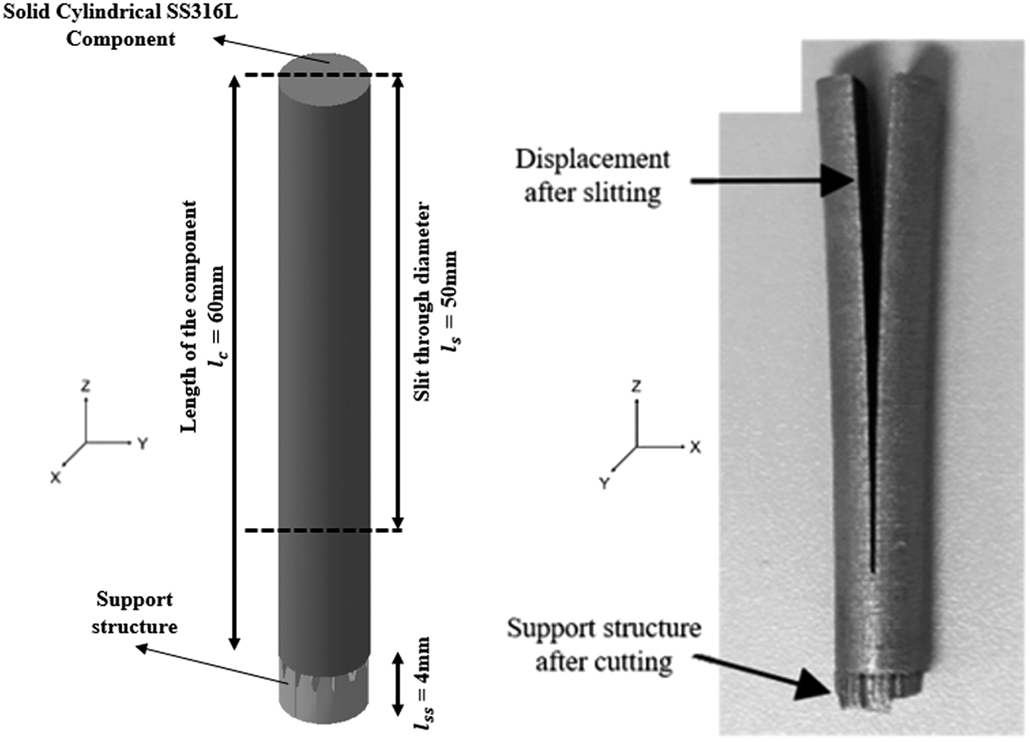
Schematic detail (left) and printed result of SS316L cylindrical component (right).
Selective Laser Melting Build Parameters
Numerical Computation Methods and Optimization Procedure
Generally, there are two well-known numerical computational methods used in the prediction of mechanical responses of manufactured product, which are thermomechanical method (TMM) and ISM. On one hand, TMM can be considered as a precise simulation method since visco-plastic deformation can be accurately computed. However, since the component may comprise of thousands of thin layers and a large number of scan tracks, the complex geometry of a 3D printed metal component requires a long computation time. On the other hand, fast computational time in predicting mechanical response using ISM requires calibration of specimen consisting of several experimental procedures, which include advanced measurement device such as coordinate measuring machine and machining process such as EDM. Extensive work preparation, including material usage for substrate plate, fabrication time for calibrated specimen, and mechanical cutting before distortion measurement, leads to the proposed method using method combination of TMM and ISM. This research on combined TMM-ISM with optimization method uses all principles as described below.
Principle of mesoscale TMM-based simulation
In general, the governing equations for TMM-based simulation are based on transient 3D heat conduction equation as defined in Equation (1) in which T, ρ, Cp, k, Q, and v are temperature, density, specific heat capacity, thermal conductivity, absorbed heat, and laser scanning speed.
Since SLM process is considered a closed system, 3D heat conduction of SLM process can be defined as in Equation (2).
Referring to previous research
15
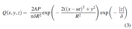
where numerical simulations were executed using commercial FE software COMSOL, applied laser during SLM process was separated into three different portions, which included reflection, absorption, and transmission of power. During printing process, only the absorbed energy was used to melt the powders. The laser energy can penetrate a certain depth through the powder bed. Volumetric heat source from Beer–Lambert attenuation law was applied by considering laser penetration in the depth direction. Volumetric heat source used in mesoscale simulation can be expressed in Equation (3) where A is the laser energy absorption, P is the laser power, δ is the optical penetration depth, R is the effective laser beam radius,
In another research
16
using commercial FEM software MSC Marc/Mentat, the stacking of multiple powder layers that became bundles with thickness of one element was modeled and called as lumping. An equivalent energy input was applied simultaneously onto full or partial layers in a one-time step. The energy input into each point of the part correlated with many factors such as hatching distance, the spot focus, scanning speed, absorbance of the powder, wavelength of the laser, or the powder of the laser. However, extensive computational time was needed, and heat flux density was used in the simplification of a simultaneous heat flux onto full layers, while experiencing the same amount of energy fed into a volume of element, V = Δx·Δy·Δz. The applied total energy is defined as the multiplication of the energy density, the applied time, and the volume. Equation (4) describes the applied total energy where q is the applied heat flux and v is the laser speed.
The applied heat flux density for calculating the total energy input shown in Equation (4) can be drawn from microscopic level where μ, Plaser, dspot, ddepth, and dhatching are the laser efficiency, the laser power, the laser spot, the laser depth, and the laser hatching distance.
Equation (5) describes the latent heat transfer associated with powder melting and melt pool solidification, where q represents the energy released or absorbed during phase change, m the mass of the substance, and L the specific latent heat of fusion. 17 The latent heat properties used in this simulation for defining the phase of SS316L are shown in Table 2.
Latent Heat Properties for SS316L
Heat loss by conduction, qcond through the powder, and metal component in SLM process can be described in Equation (6) where k is the thermal conductivity and T is the temperature.
Heat loss by convection, qconv, through the nearby environment can also be expressed by Newton's law as described in Equation (7) where Tm, Te, and hconv are temperature of the melt pool, temperature of the gas inside the chamber, and the heat convection coefficient through the surrounding environment, respectively.
Radiation plays an important role in the heat loss mechanism of the heat affected zone (HAZ) due to the high temperature field induced by the moving heat source. Heat loss by radiation qrad in SLM process can be expressed in Equation (8) where σ is the Stefan–Boltzmann constant,
The absorbed energy Q from the heat source utilized for melting the powder in SLM process can be written as in Equation (9) where q is the energy dissipated from the moving heat source.
In this study, TMM simulation on simplified calibration specimen was executed since both thermal and visco-plastic deformations can be accurately computed. Solid cylindrical component was built on a Renishaw AM250 using austenitic stainless steel 316L metallic powder. In this executed simulation, material data for SS316L powder properties covered various temperature-dependent properties such as thermal conductivity, expansion coefficient, specific heat capacity, and Young's modulus. The material data were calculated using JMATPRO software, which combined the calculation of thermodynamic properties using CALPHAD (Calculation of Phase Diagram) method followed by equilibrium of phase diagram.19,20 The chemical composition of SS316L powder, as well as SS316L base plate, was referred to Simufact Material 2020. The temperature dependent material data used for SS316L powder and base plate is shown in Figure 2.
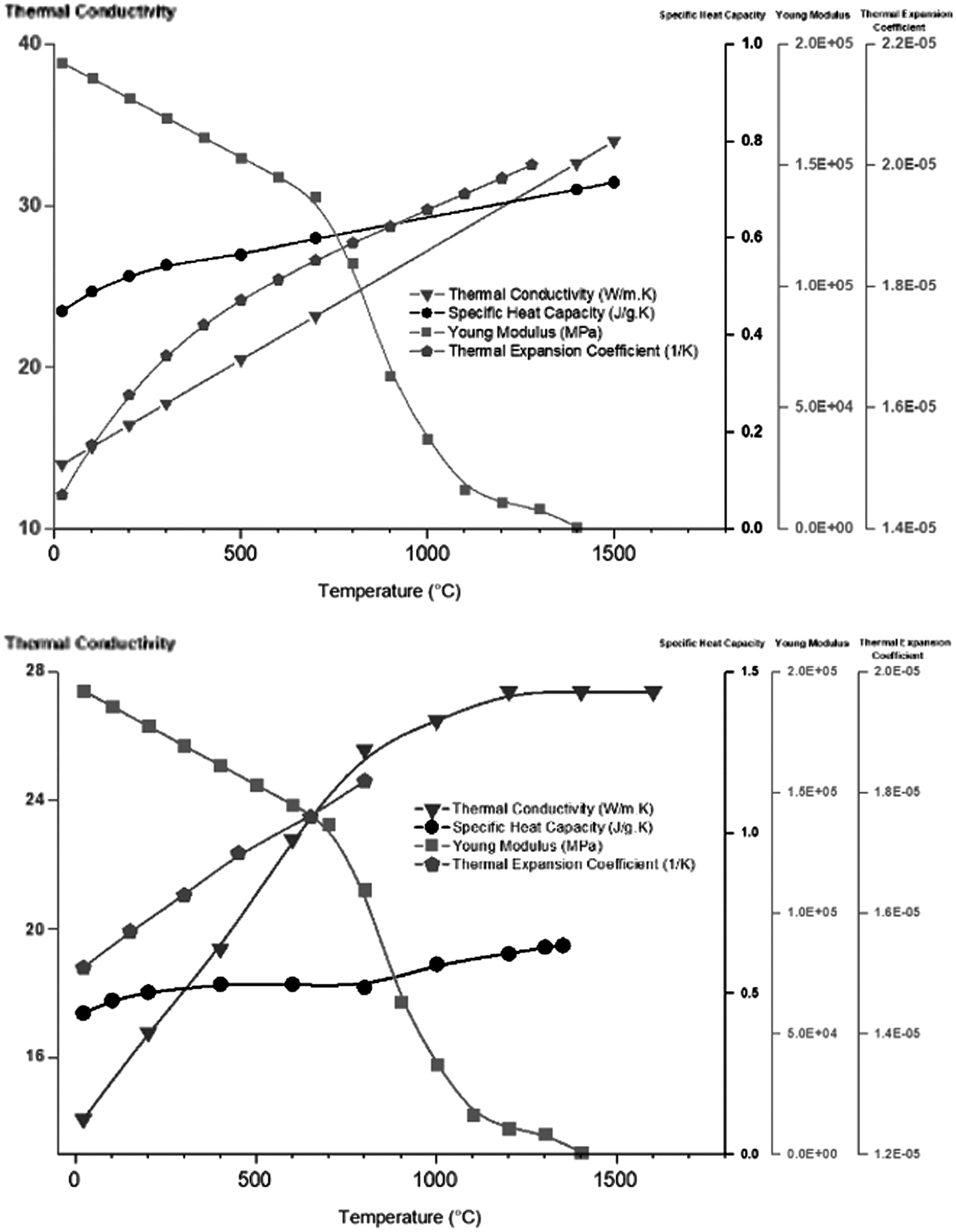
Material properties for SS316L powder (top) and base plate (bottom).
Isotropic hardening was implemented throughout the analysis where the phase transformation was neglected. From the stress–strain graph, after reaching the maximum plastic strain defined, the value of the flow stresses was extrapolated and remained constant to ensure the stability of the numerical simulation. Both SS316L powder and base plate used similar temperature dependent flow stress and strain rate data as shown in Figure 3. The density of the calibration specimen and support structure assigned in this mesoscale simulation was 7966.0 and 6732.8 kg/m3, respectively. The shell thickness for the support structure was 0.3 mm, and the support structures were generated at the overhang angle of the simplified calibration specimen.

Flow curve for SS316L powder and base plate.
Modeling and simulation were executed using specialized FEM software Simufact Additive 2020. Executed TMM simulation consisted of SLM process parameters and cutting through the middle of solid cylindrical component as shown in the previous chapter. The geometrical model for this SLM process of fabricating solid cylindrical component cutting consisted of four major components which were base plate, solid cylindrical component, support structure, and cutting plane as shown in Figure 4. The dimension of the base plate was (250 × 250 × 30 mm). The type of meshing utilized in this numerical model was hexahedral element with uniform voxel size of (1 × 1 × 1 mm), which was determined by sensitivity analysis carried out before process simulation. Coarser mesh was applied at the base plate since there was no interest on base plate deformation. The actual printed layer was 50 μm; however, in this simulation, solid cylindrical component consisted of 130 layers, including 4 mm support structure. Process parameters assigned such as laser power, laser speed, hatch distance, and layer thickness of this TMM-based simulation are presented in Table 1.
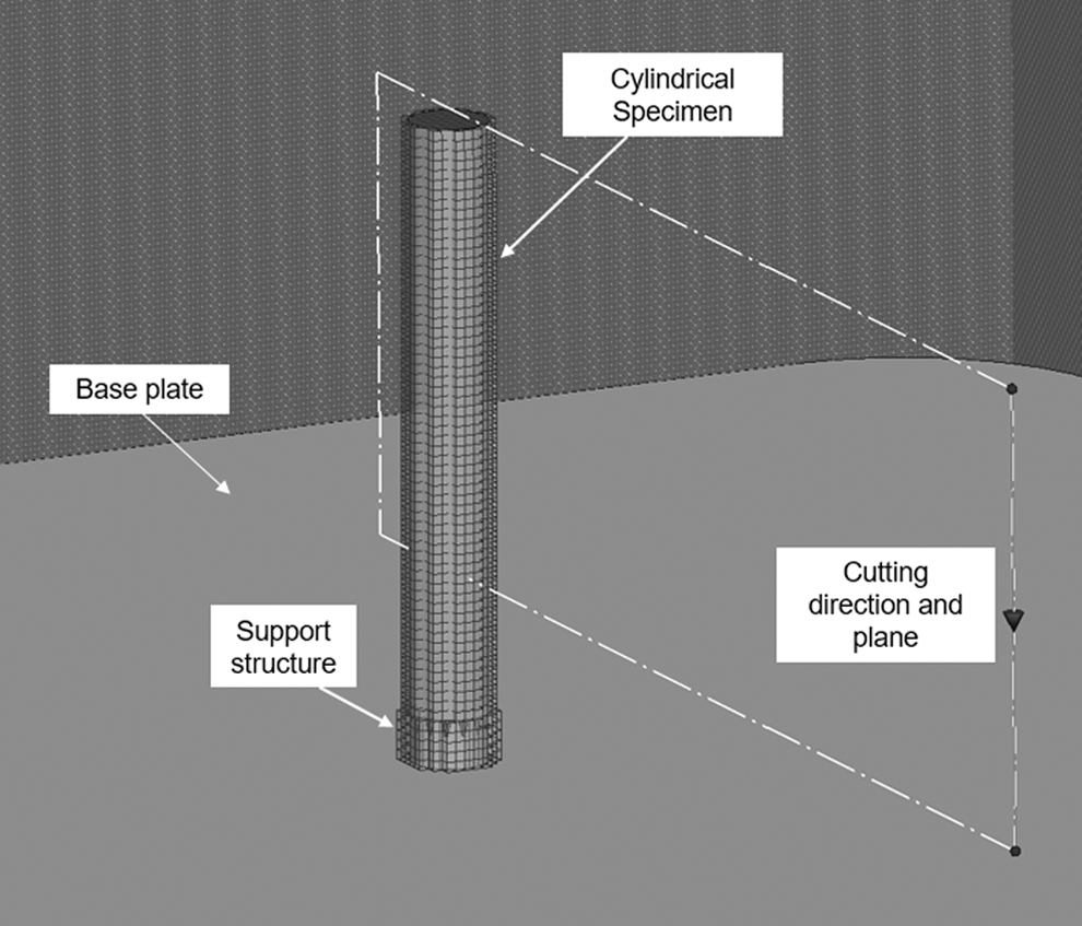
Geometrical modeling for simulation of solid SS316L cylindrical component.
Principle of macroscale ISM-based simulation
In LPBF process, metallic powder material along the laser scan is heated, melted, and solidified repeatedly in a short time span. The total strain induced in the melting and solidifying process of the metal part can be written as in Equation (10).
where ɛtot is the total strain and ɛe, ɛp, ɛth, ɛpt, ɛcr are elastic strain, plastic strain, thermal strain, phase transformation, and creep strain, respectively. However, creep strain can be neglected since the changes are relatively small,
21
as well as strain caused by solid-state phase transformation.
22
Remaining total strain can be written as in Equation (11).
After the metallic powder is solidified and cooled down to the ambient temperature, thermal strain component is offset to zero and transformed to plastic strain after undergoing a heating–cooling process cycle.
23
The inherent strain can be considered as the plastic strain that remains in the HAZ. The inherent strain equation can be expressed in Equation (12), where ɛ* is the inherent strain. Mechanical response on metallic component manufactured by LPBF process can be predicted after inherent strain components are defined.
ISM is used for computing the mechanical response on additively manufactured metallic component based on theory of infinitesimal strain in which the deformation of a solid body is analyzed in microscale displacements of the material particle as shown in Figure 5 illustrating the infinitesimal theory from steady (a), stress (b) up to stress-released state (c).

Infinitesimal strain theory for ISM. ISM, inherent strain method.
Lo and L are assumed to be the length between two points at the standard and stressed state before and after the process, respectively. The distance between the two points becomes L* once the residual stress is released through relaxation by removing the infinitesimal element comprising the two points. The inherent strain in the element is defined as a ratio of the residual strain in the stress-released state, as well as in the steady state, where the residual strain in the steady state is used as a reference. Hence, Equation (13) can be written as follows:
The metal component is cooled to ambient temperature after the process, and the thermal strain in the part is dissipated. Thermal strain is not a concern here because the reference temperature is the ambient temperature of the entire system. Only mechanical strain is involved which can be written in Equation (14) as follows:
In LPBF technology, the metal component is built in a powder bed through repeated micro-welding process. 24 As a result, thermal and mechanical strain (both elastic and plastic) and strain due to phase change will be generated and re-equilibrated throughout the welded section. Since the strain caused by phase change is relatively small compared to the other two kinds of strain, it is usually ignored when computing the inherent strain.25,26 After welding is completed, the part cools to the ambient temperature. Hence, the inherent strain (ɛ*) can be defined as the total mechanical strain (ɛtot) after the welding is completed deducted with the next term of mechanical elastic strain (ɛe), which is directly proportional to the stress released. When the inherent strain components are known, ISM using linear elastic FEM can be executed for fast prediction of distortion. Figure 6 shows the workflow for the calculation of elastic FEM analysis.

Elastic FEM analysis procedure. FEM, Finite Element Method.
Based on the equations in Figure 7, {ɛ*}, {f}, and {u} are vectors for inherent strain, nodal force, and nodal displacement, while [B], [D], and [K] are differentiator matrix, constitutive matrix, and stiffness matrix, respectively. Based on elastic FEM shown in Figure 6, deformation can be computed by applying the inherent strain value as an input. Based on general elastic FEM analysis, total deformation is computed by the applied structural load per unit.
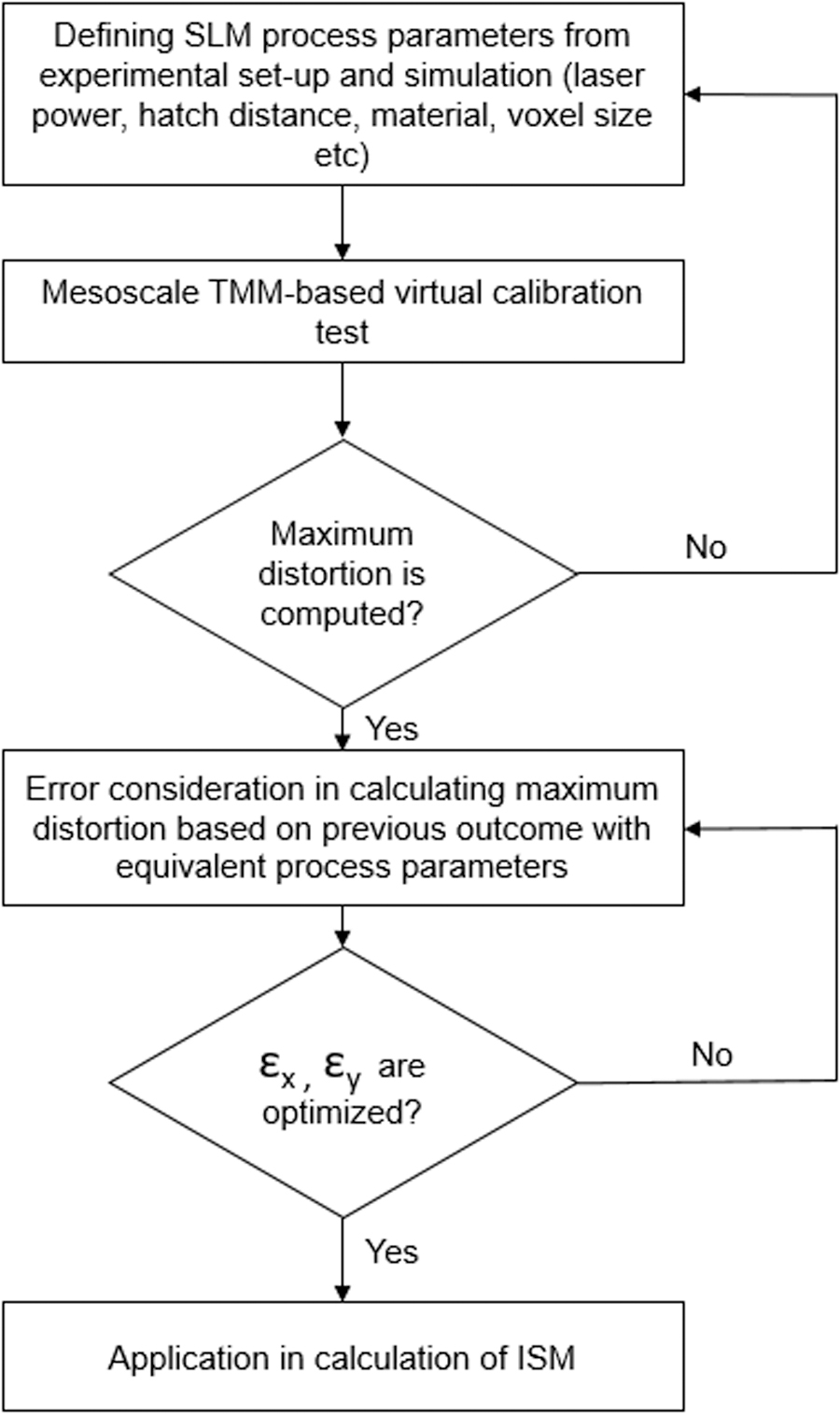
Proposed workflow for combined TMM-ISM simulation. TMM-ISM, thermomechanical—inherent strain method.
New approach of TMM-ISM-based simulation
The main objective of combined TMM-ISM is to predict the mechanical response on additively manufactured SS316L solid cylindrical component such as distortion and residual stress with fast computational time without experimental calibration process. To simulate the mechanical response on additively fabricated SS316L solid cylindrical component, inherent strain components with respect to longitudinal and transverse directions need to be optimized before performing ISM. TMM simulation is executed by assigning real process parameters such as laser speed, laser power, layer thickness, and so on to predict the maximum distortion on simplified calibration specimen.
Furthermore, computed maximum distortion from TMM is used as an input for N-M pattern search to find the minimum error. The optimized inherent strain tensors with respect to longitudinal and transverse strains are used as input for macroscale model to predict the distortion of solid cylindrical component. The workflow for this research can be seen in Figure 7.
Virtual calibration test using TMM-based simulation
The virtual calibration test is conducted using mesoscale TMM-based simulation, which follows the geometrical modeling and cutting plane as shown in Figure 8. Since build process parameters such as laser power, laser speed, hatch distance, hatch type, and layer thickness affect the resulting distortion of simplified calibration specimen after subsequently cutting the support structure, the process parameters used in this mesoscale simulation of calibration process are presented in Table 1.
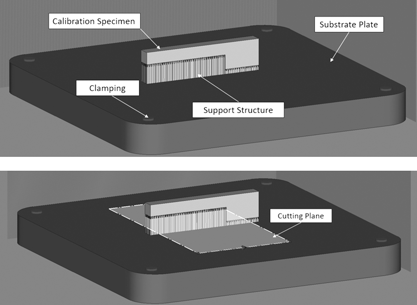
Geometrical modeling (top) and cutting plane (bottom).
In the build properties of TMM simulation, laser parameters such as laser power, speed, efficiency, and beam width are defined based on real application from SLM machine. Layer thickness and recoater time are determined in layer properties where layer thickness is from each built layer and recoater time is the time taken for the cooling. Process parameters in Simufact.AM can be seen in Table 3.
Process Parameters for Input Data in Simufact.AM
In this basic investigation, mesoscale virtual calibration test is conducted based on isotropic strain type using one cantilever with two inherent strain components, which have longitudinal and transversal directions to the laser scan vector. The selection of isotropic strain type is expected to be sufficient due to the simple cylindrical model geometry with middle cut and anticipated distortion direction on major X-axis. In addition to that, the latest version of the implemented FEM software suggests one specimen for isotropic and two for orthotropic strain type, which should be used for large and complex geometrical model with severe distortion direction. Furthermore, simple bidirectional parallel laser scanning with rotational angle of 67° is used in mesoscale virtual calibration test and cylinder following the experiment as described in Davies et al. 14
In the TMM simulation for virtual calibration test, heat flux parameters consisting of exposure time, exposure energy fraction, and volumetric expansion factor are to be determined as the boundary conditions. While exposure time is the duration of time used to apply the volumetric heat flux of each powder layer of material, exposure energy fraction is determined by a higher volumetric heat flux in the exposure time and a lower volumetric flux during effective time. During the exposure time, the energy is used mainly to melt the metal powder, and the remaining will reheat the solid material after the exposure time. Volumetric expansion factor is defined as the thermal expansion and shrinkage effects caused by the modeling approach, which combines multiple powder layers and repeated heating of the heat source in one element layer. Heat flux parameters used in this TMM simulation can be seen in Table 4.
Heat Flux Parameters for Input Data in Simufact.AM
Furthermore, the information of inherent deformation from TMM simulation is used as an input for the optimization of inherent strain component using N-M Optimization. Within the virtual calibration test process, 11 points (P1–P11) with similar distance of 10 mm between each point are analyzed, and the selected points at the middle of the top surface of the specimen can be seen in Figure 9.

Referenced Points (P1-P11) at top surface of specimen.
Optimization using N-M method for calculating inherent strains
In ISM, strain tensors need to be defined in predicting the distortion of cylindrical component manufactured using LPBF. To find the inherent strains, optimization method was developed and formulated as investigated by Ravichandran.
27
In general, original optimization formulation can be expressed in Equation (15):
Where ri is the difference between maximum distortion from experiment and simulation, i is counter, and n is the number of sample points. The main objective is to optimize certain variable by finding the minimum value of error during iterations. In this study, the equation of optimization was modified as a new formulation written in Equation (16). In this study, distortion value from the experiment was predicted using TMM-based simulation since both thermal and visco-plastic deformations can be precisely computed. The function used in finding the minimum error can be expressed by uTMM and utot, which are the distortion values from TMM as stated in Equation (16), respectively.
The equation used to calculate longitudinal and transverse shrinkage is based on the work of Murakawa
28
as written in Equation (17) where utot, ɛx, ɛy, and L are total distortion from simplified calibration, the longitudinal strain, transverse strain, and the length of laser scan, respectively.
In this study, N-M optimization algorithm was used where simple regression was used for optimizing the inherent strain values with minimum error between resulted distortions. Principally, N-M optimization applies direct search method in solving the unconstrained parameters
29
in which the vertices change with each iteration.
Referring to the order from Equation (18), X1 is considered as the best vertex and Xn + 1 as the worst one. If several vertices have similar objective values, tie-breaking rules are required for the method to be well-defined. 21 In this study, the selected programming language in MATLAB was used in finding the minimum of unconstrained multivariable function using derivative-free method. The process that began by evaluating the function at initial point followed by exploratory moves until the calculated error from functional value was below the termination tolerance which was set at 0.003. The workflow for optimization process in MATLAB can be seen in Figure 10.

Self-developed Algorithm for finding inherent strain values using Nelder–Mead optimization method.
Result and Discussion
The findings consisted of the result from TMM executed by Williams et al. which was then compared with the fabricated solid cylindrical SS316L. Furthermore, TMM-based simulation and new approach TMM-ISM-based simulation were performed similar to Williams et al.'s mentioned work. TMM-based simulation is a direct approach, while TMM-ISM-based simulation is a process which consists of virtual calibration test and optimization of inherent strain values. All results from the procedure mentioned above are discussed in this section.
Results on case study from past research
Coupled TMM FE analysis was executed using ABAQUS software. From the past research, all elements were deactivated initially before being re-added layer by layer using element birth technique. A predefined temperature field was applied into the geometry in which each layer was reactivated with a temperature of 1400°C, by referring to the melting temperature of SS316L. 13
From the result, the validation of simulation showed good agreement within ∼5% of accuracy compared to experimental result. Figure 11 shows the vertical cylinder's inside cut surface's horizontal deflection in Y direction against build up direction in Z direction.

Distortion validation on vertical cylindrical component. 13
Results on case study using TMM-based simulation
In this TMM-based simulation, the geometrical modeling and material modeling were based on section Principle of mesoscale TMM-based simulation. The geometrical modeling consisted of three major components which were base plate, solid cylindrical component, and support structure. The material modeling used in this TMM-based simulation was temperature dependent material data to get accurate result regarding mechanical response such as distortion. The mentioned temperature was dependent on material data such as thermal and mechanical properties of SS316L powder, as well as the flow curve discussed in section Principle of mesoscale TMM-based simulation. For this study, Simufact.AM was used for TMM-based simulation, and the main considered parameters used can be seen in Table 3.
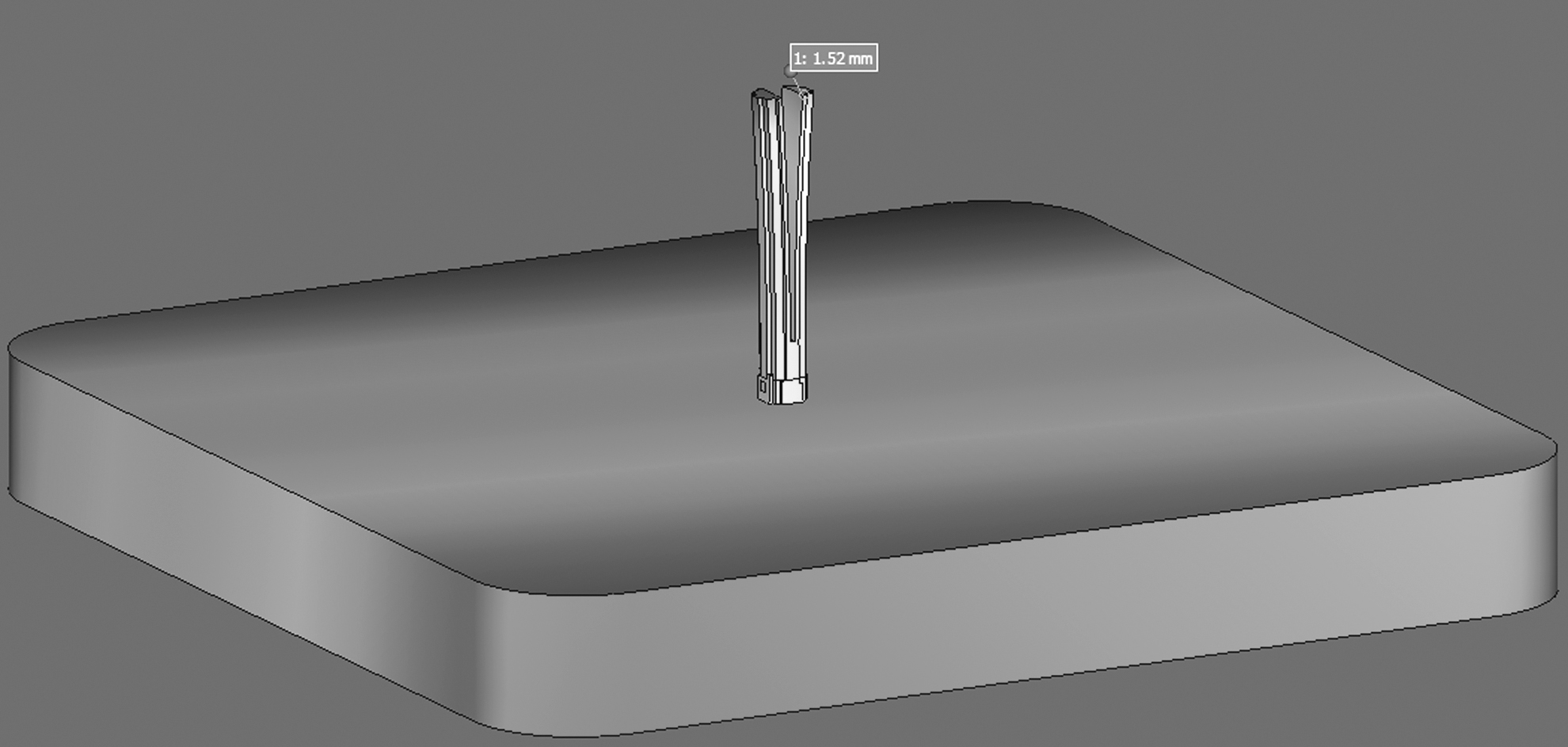
Simulation started with sensitivity analysis with regard to voxel element size. Six TMM-based simulations with different voxel element sizes of 0.6, 0.8, 1, 2, 3, and 4 mm were executed, and the result of each simulation can be seen in Figure 12. Voxel element sizes of 0.6, 0.8, and 4 mm were not successfully computed, and the simulation ended with error. For the voxel element size of 2 and 3 mm, both simulations were successfully computed at the build stage layer by layer of the cylindrical component; however, the cutting stage could not be computed. Finally, voxel element size of 1 mm showed a good result where both build and cutting stage were successfully computed using TMM-based simulation. Due to this fact, 1 mm voxel element size was selected for all simulations of this case study. Another important reason for creating the voxel mesh with proper size of element is to model the part as close as possible to the actual shape. 12 This is to hinder miscalculation during simulation which can affect the performance and final outcome.
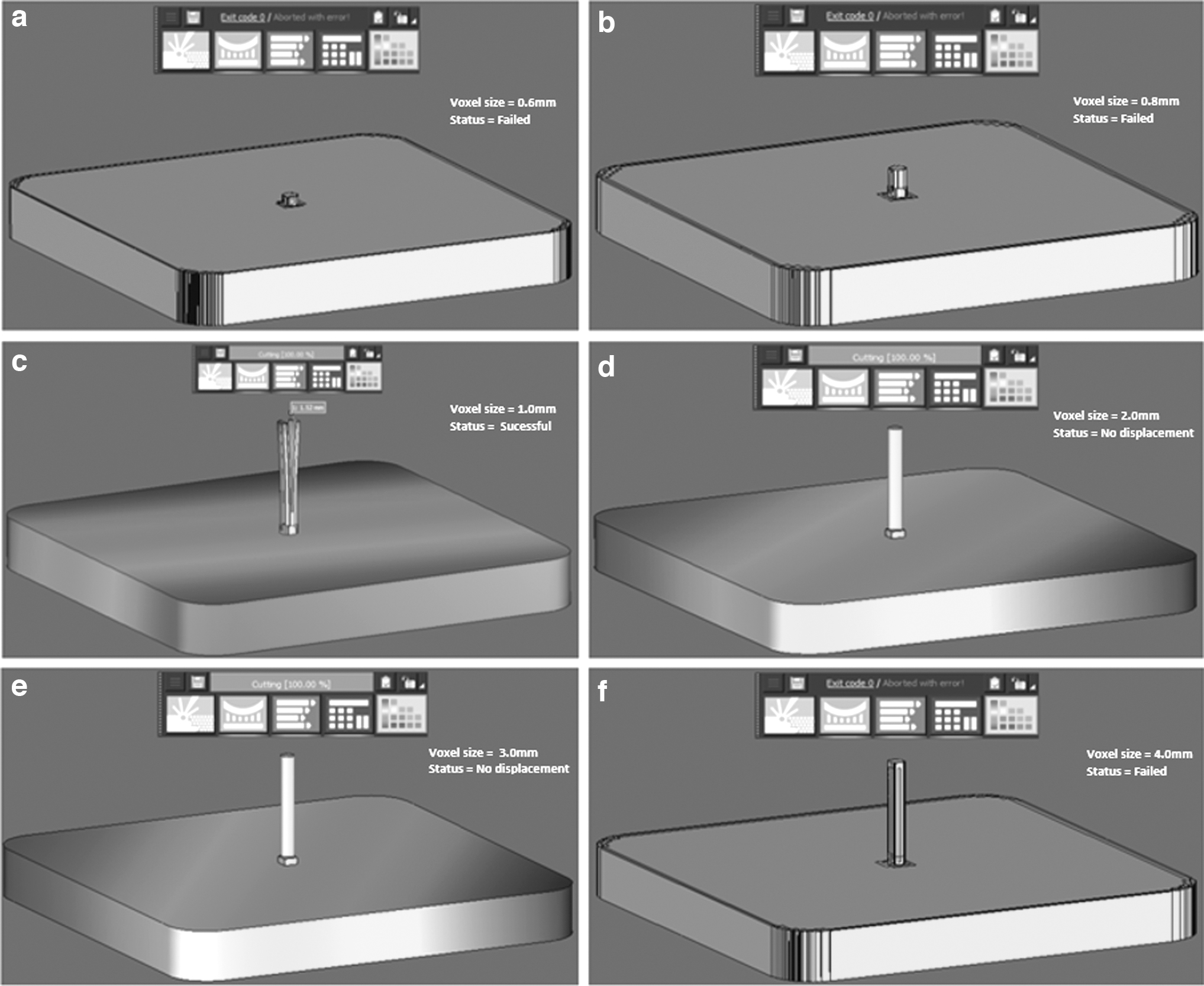
Results of mesh sensitivity analysis.
The result for mesoscale TMM in predicting the distortion of cylindrical component was in good agreement with 3.8% of error compared to experimental distortion data from Williams et al. which can be seen in Figure 13.
Result of mesoscale TMM on solid cylindrical component.
Case study results using TMM-ISM-based simulation
This method started with TMM analysis in the calibration process as to define the mechanical response. Afterward, the inherent strain tensors were optimized, and the tensor was used as an input of ISM in predicting the distortion of additively manufactured cylindrical component made of SS316L.
Results of TMM-based virtual calibration test
In TMM simulation, distortion on the simplified calibration specimen happened after the support structure was subsequently cut. This is due to the reduction of residual stress in the specimen after removing the support structure. Resulting distortion with respect to Z-axis of each point was measured, and resulting distortion can be seen in Figure 14. The maximum distortion computed by TMM simulation on simplified calibration specimen was 0.88 mm. For optimizing inherent strain tensors, 0.92 mm was used as an input which included 3.8% of validation error computed using purely mesoscale TMM in predicting the distortion of solid cylindrical component.
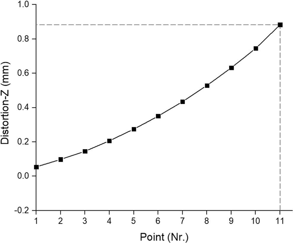
Distortion results of virtual calibration test.
Results of optimization of inherent strain value
The result of distortion from calibration process was used as an input in solving the optimization process in which MATLAB software was used as a tool for finding the minimum error of the function. Twelve iterations were executed to satisfy the termination criteria of OPTIONS.TolX and OPTIONS.TolFun with the minimum error of 0.1% applied which means that if error of the function value is less than the limit, the program is terminated. Figure 15 shows N-M optimization process in finding the minimum error for both longitudinal and transverse inherent strain tensors. During optimization process, error of the maximum distortion approached zero at iteration 4, and the optimization process stopped at iteration 12 when termination tolerance was satisfied. Based on Equation (19), the optimized values of inherent strain components were −0.0022 and −0.0119 for longitudinal and transverse inherent strain, respectively.

Result for finding the minimum error.
Results of ISM-based simulation on cylindrical component
ISM is an efficient method for fast prediction of the distortions and residual stress on metallic component. The term ISM was introduced by Ueda in 197530 which referred to the total of all incompatible internal permanent strains induced by inhomogeneous inelastic deformation, temperature gradients, or phase change which generated residual stresses after the welding process. ISM sets similar geometrical model in experiment. Geometrical modeling for calibration specimen, support structure, and substrate plate can be seen in Figure 16 in which voxel size of meshing is set to (1 × 1 × 1 mm). The substrate plate is set to be coarser mesh size, the layer thickness is set to 50 μm, and the layer rotation parameters is set to 67° for each layer built.

Geometrical modeling for macroscale simulation.
Optimized inherent strain components with respect to longitudinal and transverse direction were used as input in executing the macroscale simulation for fast prediction of distortion with respect to X-axis on cylindrical component. Result from ISM in predicting the distortion of cylindrical component is shown in Figure 17. Maximum distortion computed on vertical cylindrical component for both sides was 1.43 mm.

Result of distortion on cylindrical SS316L component.
Discussion on overall results
Pure TMM and combined TMM-ISM using Simufact Additive 2020 were implemented to predict the distortion of cylindrical specimen after slitting. Due to the release of residual stress after cutting process, distortion happened on cylindrical specimen. Figure 18 shows the distortion result with respect to X-axis from experimental data and ISM simulation. All three simulation methods showed good agreement in terms of result accuracy, which was between 3.8% and 9.5%, as well as similar trend of distortion after slitting cylindrical component. The computational time for mesoscale simulation (TMM) was 129 min, while ISM only took 63 min to finish the simulation which included calibration, optimization of inherent strain values, and macroscale simulation. Unfortunately, there was no report of computational time for TMM simulation made by previous researcher, which was assumed to have similar length of computational time of pure TMM in this research. Percentage error and computational time for this research are shown in Table 5.
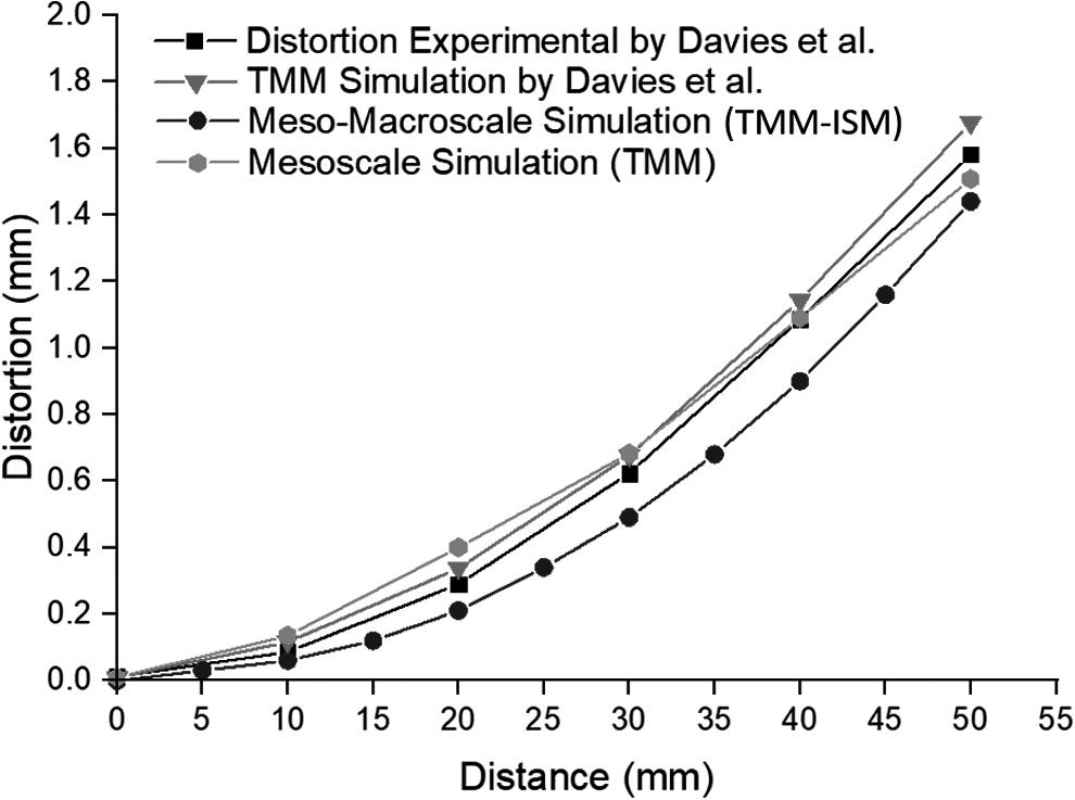
Result of the distortion analysis.
Error and Computational Time for Distortion Analysis
TMM-ISM, thermomechanical—inherent strain method.
Conclusion and Further Recommendation
This investigation focuses on a pure TMM and newly proposed TMM-ISM-based simulations which included simplified optimization method in calculating inherent strain tensors. The highlight of this study is by neglecting the needs of experimental setup in calibrating inherent strain components. These combined simulation methods involved a modeling approach starting from TMM-based virtual calibration test up to ISM simulation in which all parameters such as geometry, process parameters, and boundary conditions are set in a similar manner to ensure the realistic comparison with experimental and simulation case study.13,14 According to the results of this study, the following conclusions can be drawn:
The investigation on distortion of additively manufactured cylindrical component using two different numerical computation methods, namely TMM and ISM, has been successfully executed. Since the fabrication and measurement of calibrated specimen require huge intensive effort, it can be replaced by mesoscale TMM-based virtual calibration test with error consideration which can stem from previous research with equivalent process parameters. The considered error is used to find the maximum distortion before optimization of inherent strain tensors. Inherent strain tensors with respect to longitudinal and transverse directions are successfully optimized using N-M optimization method. The result of the distortion from mesoscale TMM-based simulation and combined TMM-ISM shows a good agreement with errors of 3.8% and 9.5%, respectively, compared to experimental distortion. Combined TMM-ISM speeds up the computational time up to almost 50% compared to purely mesoscale TMM in the prediction of distortion of solid cylindrical SS316L component. Virtual Calibration Test using one specimen with isotropic strain type is sufficient for simple geometry and laser scanning strategy such as uni- and bidirectional leading to specific major distortion direction. Different material properties between software material library and powder suppliers, as well as fluctuating process parameters, can give huge effects to the simulation accuracy.
As further recommendation, the following research focus can be conducted:
Established cantilever geometries with simplified and complex design based on successful literature data or own experiments should be prepared for virtual calibration tests.
More complex component geometry should be manufactured and analyzed using proposed method.
Other material should be investigated which can be modeled using material modeling software based on the chemical compositions.
Material compositions should be analyzed using more advanced equipment such as SEM/EDX (Scanning electron microscopy with energy dispersive X-ray spectroscopy) or GD-OES (Glow Discharge Optical Emission Spectroscopy).
Footnotes
Acknowledgment
The authors would like to express their gratitude to the staff members of Smart Manufacturing Research Institute (SMRI), Advanced Manufacturing Laboratory and Research Interest Group: Advanced Manufacturing Technology (RIG:AMT) at School of Mechanical Engineering, Universiti Teknologi MARA (UiTM) Shah Alam.
Author Disclosure Statement
No competing financial interests exist.
Funding Information
This research is financially supported by Fundamental Research Grant Scheme (FRGS) with Project Code: FRGS/1/2019/TK03/UiTM/03/5 and Strategic Research Partnership (SRP) Grant with Project Code: 100-RMC 5/3/SRP (016/2020).