
Abstract
The recent developments in multiaxis three-dimensional (3D) printing have got a large potential for expanding the capability of material extrusion based methods. Especially curved and nonplanar methods can improve buildability, surface quality, and mechanical performance. However, the challenges that arise from using them complicate their deployment. In this article, we propose a hybrid planar method, based on varying the layer height and deposition speed in combination with tool reorientation, that allows us to get a lot of the same benefits that come from using nonplanar layers. The goal of the method is to keep the deposition constant regardless of the overhang angle. This is achieved by simultaneous control of layer height, deposition speed, and tool orientation. The method is the most beneficial for large-scale, single-wall 3D printing, such as clay, concrete, and other composites. The main restriction of the method depends on the minimum/maximum ratio between the nozzle diameter and layer height. A description of the method is provided, and sample objects are evaluated either as trajectories or as test prints. The claims are confirmed by microscopy measurement of the contact patch width. The method as presented allows printing of overhangs up to 82.34°, can be applied to complex geometry without difficulties, and further possibilities of limit expansion are discussed. The contact patch width decreases only by 20% at the 80° of overhang.
Introduction
Material extrusion (MEX) based three-dimensional (3D) printing is the most common type of 3D printing today, uniting techniques such as Fused Deposition Modeling, Freeform Filament Fabrication, or clay and concrete 3D printing. Its main benefits are the ease of implementation, wide variety of materials, and the capabilities of multimaterial or composite printing. The method also has intrinsic properties such as stair stepping, limited buildability, and anisotropy—most significantly in the direction of the build—all caused by the rasterized nature of the layer-by-layer process. 1
Multiaxis 3D printing, and especially nonplanar 3D printing, has the potential to expand the boundaries of MEX based methods. These methods can completely or partially solve the problems caused by the layer-by-layer printing process. However, they also bring new difficulties in process planning, computation, and design limitations.2,3
Overhang buildability of conventional FDM 3D printing is limited due to the ability of subsequent layers to adhere to each other. This ability decreases as the contact patch width becomes smaller with increasing overhang angle—the common limit is 45°, but the actual value is dependent on the width/height ratio of the deposition. Users of FDM machines report printable overhangs in excess of 60° with the use of high ratios. However, this is a long-standing limitation of FDM printing. 4
This article aims to present an easy to implement transitionary approach, which may be most beneficial for use with large nozzle sizes and single wall deposition, a strategy commonly deployed with screw extruders. This approach combines variable layer height, deposition speed, and tool orientation with planar layers and should significantly expand the buildability while being easy to implement and combine with other methods. The potential in expanding planar multiaxis methods has been noticed by other researchers. 2
State of the art
Keeping the height constant independently on the overhang angle and orienting the extruder along the surfaces' local tangent is not a novel idea and has been previously demonstrated, for example, by Gosselin et al. 5 However, slicing objects in a way that maintains equal layer height introduces curvature into the layers, due to differences in geodesic distances. This makes it a necessity to deal with collision checking due to nozzle interference when moving on slopes or collision of the extruder or machine with the print for multiaxis strategies. Methods to generate these layers, as well as potential limitations of the process, were presented by Xu et al 6 and by Shan et al using isothermal simulation. 7
A strategy to avoid the possibility of interference was presented by Dai et al, 8 ensuring accessibility by only generating convex layers, but this strategy has to balance with requirements on surface quality. Another nonplanar method to improve buildability works with splitting the model by its local geometry and varying the build orientation for the components.9,10 Limitations of curved layer methods include inability to print certain objects with branched topology, the possibility of collision limiting buildable geometry, and low surface quality caused by curved layer stacking. 11
In the literature, few examples of intentional in-layer height variations have been found. One of these works is presented by Pelzer and Hopmann, 12 applied to regular scale FDM machinery and focuses on accurately filling the space between top and bottom curved layers with variable layer height infill, as well as using this infill for better part reinforcement. A work that takes advantage of intralayer height variations to achieve better surface quality and detail preservation with a lower layer count for desktop FDM is the CurviSlicer. 13 Another work focusing on accurate printing of top and bottom curved shells was presented by Chen et al. 14 This work incorporates five-axis movements and presents an approach to print thin shells with curved variable thickness layers. Both articles mention collision avoidance problems and possible solutions. A new method called Continuously Varied Extrusion focuses on a related topic: 3D printing with an intralayer path width variation, to achieve better infill coverage. 15 Full Control G-Code Designer is a freely available tool that allows for these approaches to be implemented, but requires parametric definition of a model. 16 Changes in layer height also occur as a side effect of iso-parametric slicing approaches, but do not disturb the print if the differences are small enough.
Variable layer height slicing is usually done according to the “cusp height” measure, either through the entire model or adaptively, with the layer height changing based on local geometry. 17 The cusp height describes the maximum deviation of the error from the original surface. A number of slicing algorithms were developed, for example, an efficient approach of slicing based on profile analysis, or by surface roughness (Ra), or by a combination of previous criteria.18–20 Adaptive layer height and curved layer slicing have also been combined and tested for printing specific objects to bring both mechanical and surface quality improvements. 21
Methods
The proposed method avoids the issues of self-collision and surface coverage by eschewing curved layers. Instead, we claim that the goal of all the methods is essentially to keep the amount of extruded material constant independent of overhang angle, resulting in constant wall thickness. To achieve the required actual material deposition rate, we propose varying the extrusion to movement speed ratio based on local overhang angle. This is coupled with reorientation of the nozzle by five-axis motion, to keep the expanded deposition aligned with local surface tangent direction, and with variable layer height slicing, to expand the buildability achieved by the method. The resulting slightly nonplanar depositions are shown in Figure 1, and a sample part is shown in Figure 2. While the tool path is planar, the width of the deposition causes slight out of plane effect, more prominent as the overhang increases.
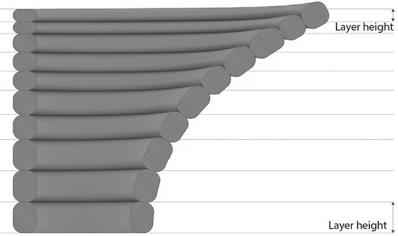
Intralayer variable thickness depositions resulting from the method.
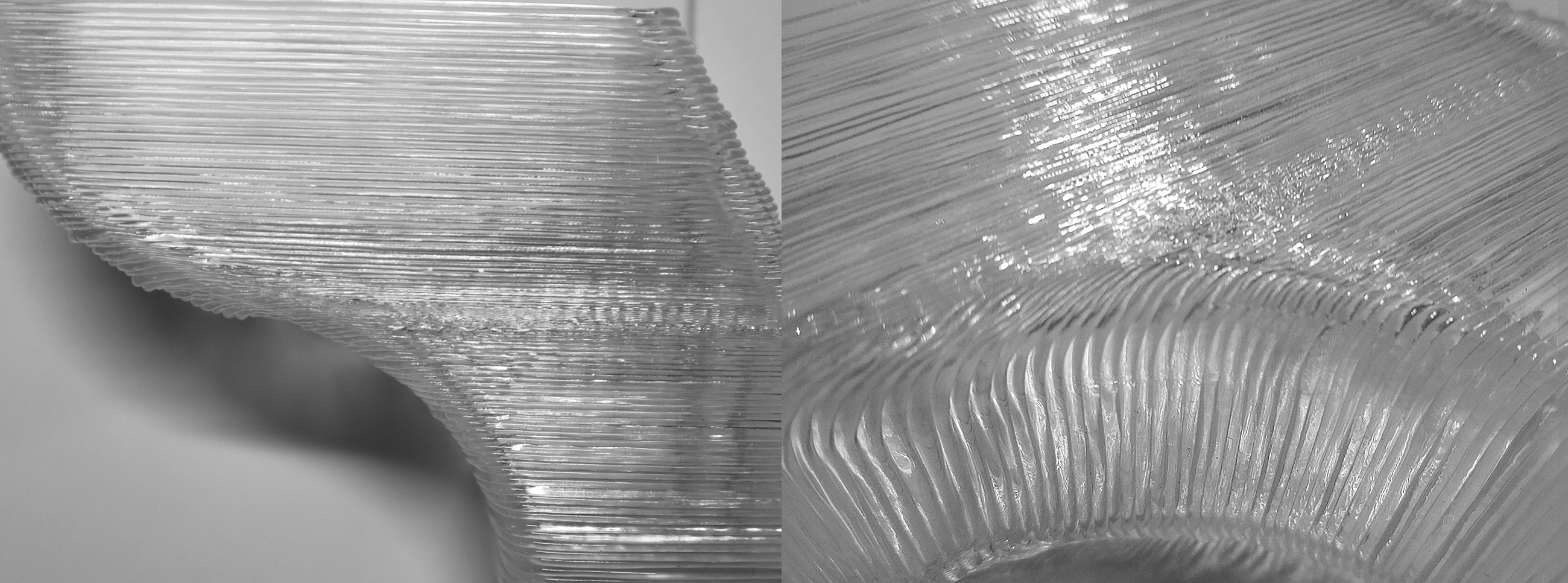
Proof of concept print with a closeup of the intralayer height changes.
The method, its flowchart pictured on Figure 3, is described in the following paragraphs.

Flowchart of the algorithm, from data input to variable height slicing and motion planning.
Maximum and minimum layer height
Variable layer height slicing is used. The limits for layer height (h) are adapted from previous research and industry practices, and for the purpose of this study, the range of 10–75% of the nozzle diameter was used.22,23 This ratio determines the maximum overhang angle (
Slicing algorithm
All slicing, computation, and motion planning is performed in McNeels Rhinoceros 7, its Grasshopper environment, built-in Iron Python interpreter, and KUKA|prc plug-in. 24
Precalculation
The input data in either B-rep or mesh form are processed using Rhinos Quadmesh command, allowing processing without the influence of poor quality meshes, such as faces with high aspect ratio. If the mesh contains faces whose overhang angle is higher than the limit of this method, they are excluded from the precalculation mesh, and these areas would have to be processed otherwise.
Variable layer height slicing is then performed by a custom algorithm (Fig. 3), considering the maximum overhang angle at any given model height. For this, a table of height coordinate matched to corresponding max. angle is calculated and used during the iterative slicing process to decide on the next layer height. A sample table is included as Supplementary Data. The relationship between the overhang angle and the layer height is linear with the sine value of the angle between the Z axis and the local normal. The initial layer height is used for 0° of overhang, and the hmin is used for the maximum overhang angle. The resulting contours can be computed either from the quad mesh or from the original mesh if available.
Motion planning
The quad mesh is also used for the tool orientation planning. The tool orientation for each point is composed of a cross product between a normal vector of the quad mesh and a vector that is tangent to the tool path and oriented to the direction of travel. The orientation is explained in the Figure 4, right. In addition to the tool path interpolation provided by KUKA|prc, the tool orientation is interpolated as well to keep the robot motion consistent.

Left: Conventional printing with constant layer height. Middle: Variable layer height with tilt (based on Krejcirik et al 27 ). Right: Tool orientation vector.
After calculating the five-axis motions, used to facilitate proper stacking of the print paths and increase surface quality (Fig. 4, left), a tilt limiter set at 45° is utilized. Tilt of 45° allows for full buildability of surfaces with up to 90° of overhang, if suitable (nonplanar) tool paths are used. 25 The tilt control algorithm works by evaluating the angle between the orientation of the intended tool axis and world Z axis. If the angle is higher than the threshold, the original vector is replaced by a one on an identical plane (described by the world Z direction and the original orientation vector), with the new angle equal to the threshold angle. As a side effect, if the extruder boundary cone is within this angle, any possibility of collision between the workpiece and the machine tool is eliminated.
Speed control
The extrusion ratio has to be continuously adjusted proportionally with varying layer height to ensure constant wall thickness. For each point of the tool path, the extrusion ratio is calculated from the local layer height—shortest distance to the following contour. For the evaluation prints, linear scaling was used. To increase precision, a scaling based on a cross-section formula could be used. The formula for a constant wall thickness is:
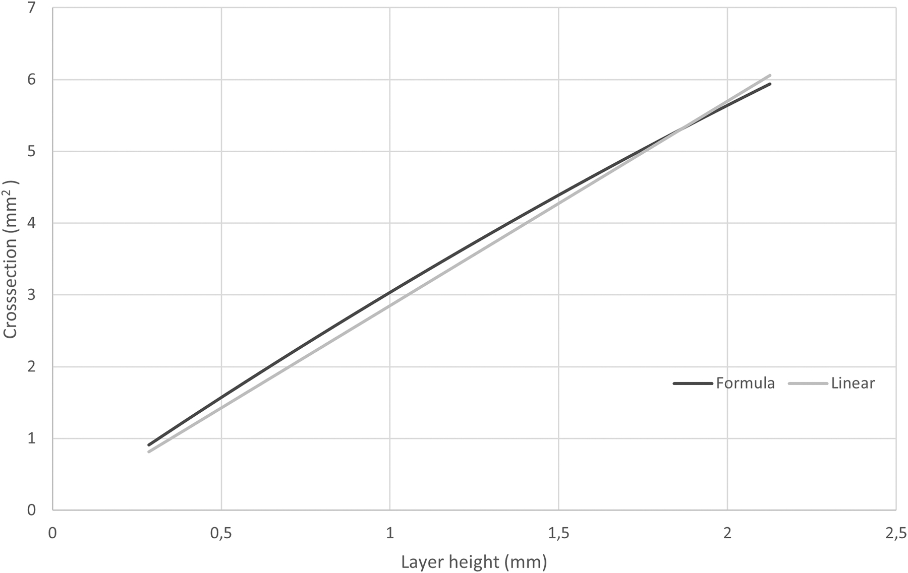
Comparison of extrusion ratio from the linear and formula-based calculations.
To avoid negative influence of the lag in material flow caused by changing Rotations Per Minute of the screw extruder, the setup has near constant RPM and it is only influenced by deviations in robot speed (e.g., when a rapid change in direction occurs). Instead, the tool center point speed changes depending on layer height. This also eliminates the influence of the nonlinear flow of the screw extruder. The speed control used to demonstrate this process was tailored to the screw extruder used, it is not an integral part of the process, and other ways to ensure correct material deposition rate could be developed. In filament setups, optimization for maximum material flow/tool speed would be possible.
Materials and machines
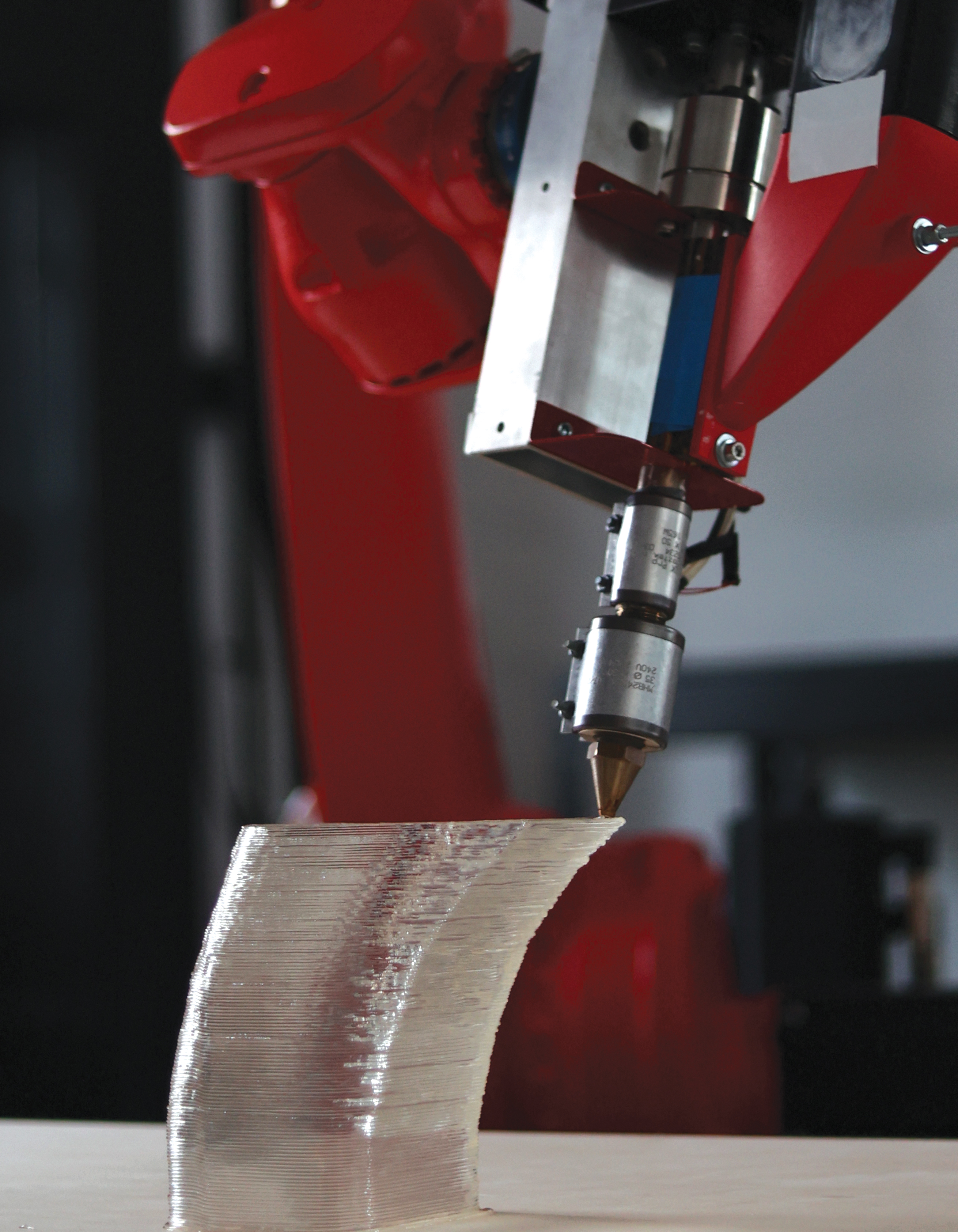
The robotic arm used for printing is a Kuka Cybertech KR16R2010-2 with a KRC 5 control cabinet. The extruder is adapted from a NOZTEK Touch filament extruder unit but equipped with a robot-coupled stepper motor for precise extrusion control. The pellet material used in the demonstration is clear PLA. The nozzle size was ø2.85 mm, with the nozzle having an elongated geometry beneficial to this method. The tip angle of the nozzle is 37.5°, and the tip length is 25 mm (The nozzle can be seen in Fig. 6). The initial layer height was 1.5 mm, and the barrel temperature was set at 210° C for both zones of the extruder. The initial tool speed was 20 mm/s. The assembly is pictured in Figure 6.
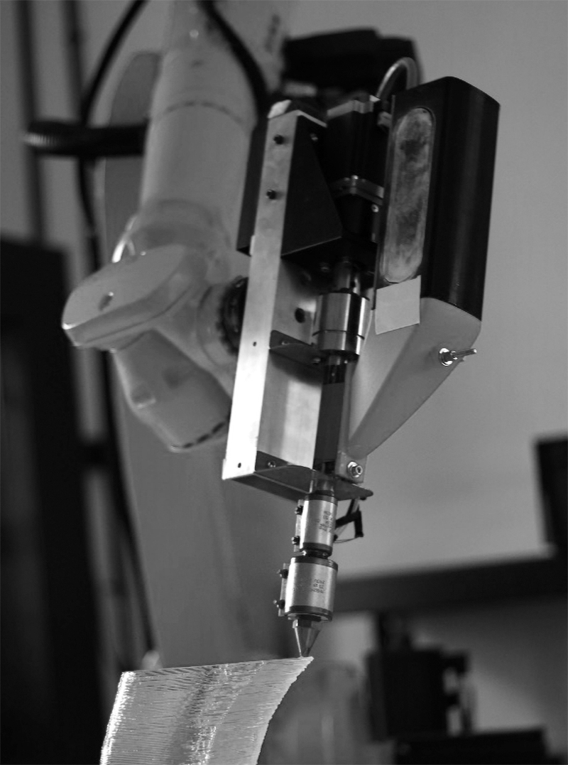
The assembly during a print.
To practically prove the presented method, an overhang tower was designed and printed; its dimensions and the location of the samples are pictured in Figure 7. Confirmation of the results was done by measuring the width of the wall and the contact patch at all tiers of the overhang tower to prove the constant material deposition independent of overhang. For this purpose, samples were taken from the towers' overhangs (Slope) and from the vertical walls (Wall). The tower was cut apart, and the samples were milled to expose the cross section. The width was then measured optically, using an Olympus 8ZX7 microscope equipped with a Canon EOS 1200D at 16 × magnification. For measurement and statistics, its accompanying software, QuickPHOTO Micro, was used.
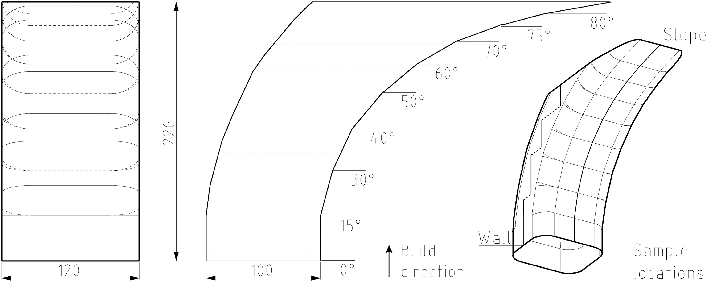
Dimensions of the overhang tower and location of the samples.
In addition, an object with a complex topology—a chain link sample—was sliced and printed to show the capability to process objects with multiple cross sections.
Results and Discussion
The printed overhang tower can be seen in Figure 8. The confirmation objects were printed successfully. Some reduction of quality was recorded in sections with the lowest layer height. Causes of this effect are unknown as the setup was able to print the lowest layer height in an isolated sample. The reduction in quality might be due to the front face of nozzle contacting the deposition. This might be reduced by reducing the external nozzle tip diameter or by slightly modifying the tilt orientation to add a tilt in the direction of travel.
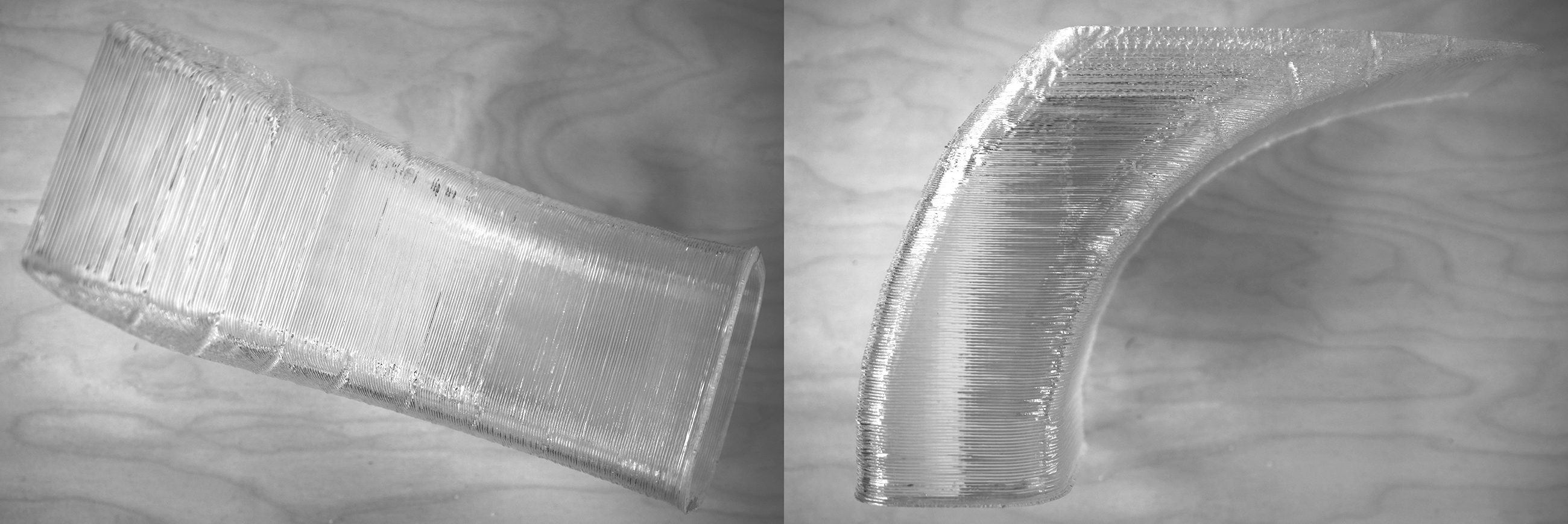
The printed overhang tower after removal from build plate.
Contact patch thickness
The goal of this method is to keep the deposition thickness constant and independent of the overhang angle. The results of the microscopy can be seen in Figure 9. The contact patch thickness was close to constant for the wall samples. The decrease of the contact patch thickness for the sloped samples was 20% at the 80° overhang segment and 12% at the 50° overhang segment. This is a significant increase over the theoretical width of the contact patch for a conventional 3D printing, which would be 0 μm at 50° of overhang for a print with the same nozzle diameter (2.85 mm) and layer thickness (1.5 mm). The conventional patch thickness was modeled based on previous research.9,26,27 The microscopy images can be seen in Figure 10. The drop at 30° of overhang is unexpected. Its appearance in both the Wall and the Slope samples suggests that it might not be related to the slicing method.
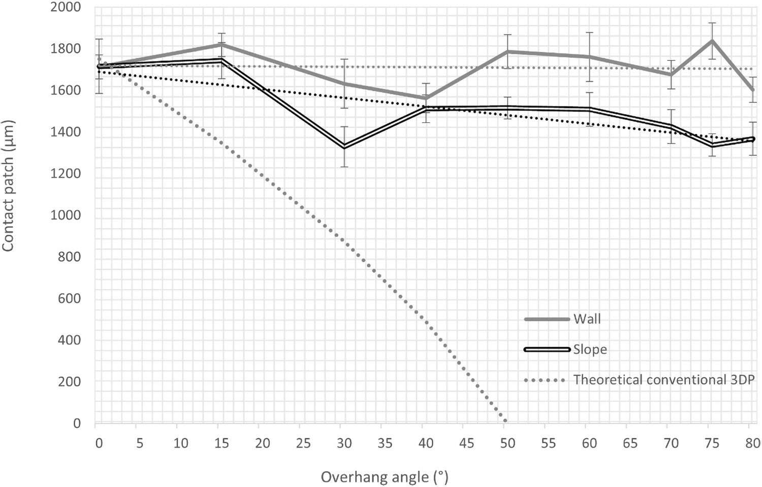
Contact patch thickness chart comparing the Wall and Slope samples based on overhang angle with theoretical values of a conventional print with the same initial parameters.
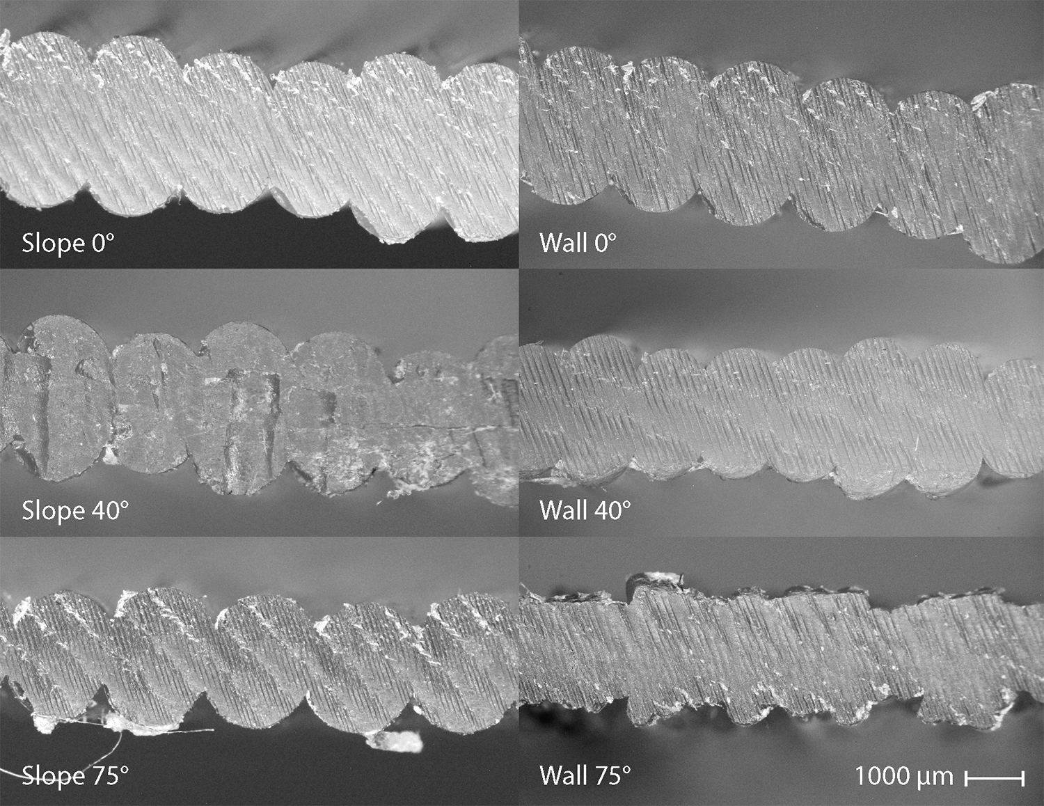
Overview of contact patch samples displaying a selected sample from the 0°, 40°, and 75° Slope sections and the corresponding Wall samples.
Wall thickness
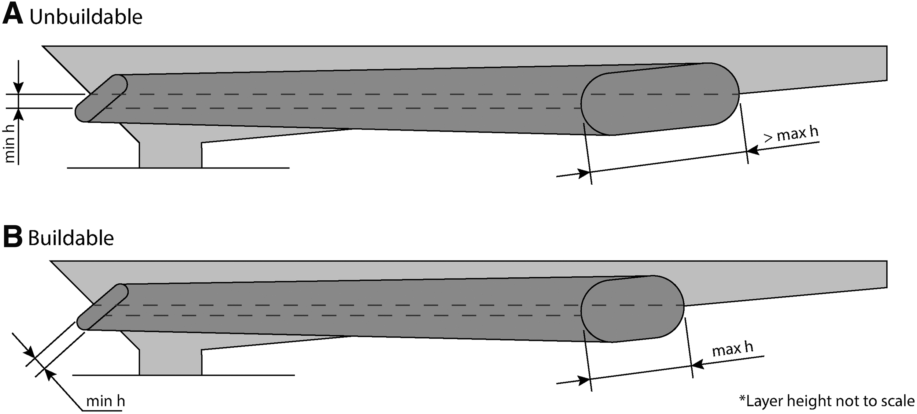
There was a slight decrease in the wall thickness of the samples (see Fig. 11). The slope samples had a consistent decrease by ∼15% from 0° to 80° of overhang. The wall sample width had decreased by about 30%, with the most noticeable decrease during the last segments; these segments also showed the decrease in print quality. The overall decrease is probably caused by sagging or shrinkage of the deposition during the print, while the decrease in the last wall segment is probably caused by the higher level of variance at low layer heights. The contact patch remained more consistent partially due to the correlation of the contact patch thickness to layer height, explained in Figure 12, and possibly due to a partial sagging of the depositions.

Wall thickness chart comparing the Wall and Slope samples based on overhang angle.

Left: Width of the contact patch correlated to layer height—the lower the layer, the wider is the contact patch; Right: The impact of this effect on buildability.
Known limitations and capability extension
The method as described is capable of printing objects up to the buildability limit, which is 82.34° of overhang. This angle is based on the combination of minimum and maximum layer height, which was 10–75% of nozzle diameter. The limit would change if other values were used, based on specific printer capabilities. The limit as used has no relation to the sliced geometry, and other parts of the method are not dependent on in either. There is no risk of extruder–geometry collision due to the applied tilt limiter. One area where problems might arise based on sliced geometry are sharp internal corners, especially in lower layer height. If internal corner radii are limited to nozzle diameter or more, this risk is significantly reduced.
The current approach works by calculating the layer heights as if each layer includes a 0° overhang segment—in other words, as if the hmin was applied to a vertical segment. An extension of this method could be gained by considering the actual lowest overhang angle in each layer—and applying the minimum layer height at that value—in regard to the actual layer height at that overhang. This will enable higher printable overhangs based on geometry, up to and excluding 90° in specific cases. A case where the build limit could be expanded is pictured in Figure 13.
Capability extension for specific geometries.
Multiaxis 3D printing can function even beyond the slicing limit of the described method. The near-flat areas that are uncovered by the slicing algorithm could be sliced as an actual flat area, using common approaches such as contour offsetting. This would make overhangs over 90° printable. The only modification from the two-dimensional (2D) methods currently in use would be the need to avoid printing in mid-air by only generating paths that maintain contact with previously deposited material. A sliced object that combines both types of trajectories can be seen in Figure 14.

Sliced glass with zones to be printed with 2D slicing marked in black; toolpaths are thickened for visibility. 2D, two-dimensional.
As previously mentioned, the method can be used on geometry with a complex topology. To demonstrate this, a chain link sample with sections that both branch apart and connect back together was printed. The finished print (after postprocessing) can be seen in Figure 15, together with a flower planter stand that features functional, load bearing surfaces at 80° of overhang.

Left: The chain link sample sliced and printed with the described method (Leftovers after retractions removed). Right: Flower planter stand printed with the described method, as printed and in use.
In addition to the abovementioned optimization for maximum tool speed, optimization for layer height could be added. Currently, layers with 0° overhang angle are printed with the nominal layer height, optimized for quality. Instead, the max. layer height could be used. This would reduce build time for setups where movement speed is the limiting factor, instead of the extruder.
A future study of effects of this method on mechanical properties should show improvements. The expectation is that samples printed with this method would outperform conventional samples but be bested by nonplanar/curved methods, as those offer more contact between layers. The effect on solid parts could also be explored, the methods is expected to be less beneficial, as it will have no effect on internally facing walls, and will bring only a minor benefit over variable layer height printing—the overhang buildability of external contours should improve.
Conclusions
A new multiaxis 3D printing method for thin shells is presented in this article as an alternative to nonplanar/curved layer methods. It combines approaches of adaptive layer height slicing and multiaxis 3D printing and presents the concept of using in-layer layer height variation intently. The result is a significant expansion of buildability and elimination of supports while keeping the deposition width stable at the same time. The processing is straightforward, as the combination of limited tilt and planar layers ensures that any geometry can be printed without the need for collision or coverage checking. The method as presented only works for objects within the buildability limit (82.34°, derived from the maximum and minimum printable layer height) and has been verified by a realized 3D print, with up to 80° of overhang printed. The method was verified by measuring the width of the contact patch throughout the print. Using the method, the width decreased by 20% at 80° of overhang, while conventionally, the width would be 0 at 50°.
The method can be combined with additional approaches to expand the buildability limit, and some of them were presented, including a way to expand the limit for specific geometry and an approach combining the method with 2D filling patterns for near-horizontal areas. The method was realized in the Grasshopper plug-in but should be feasible in any other environment. The method as described brings the most benefit to large scale single wall printing, commonly in use with screw extruders, and for vase mode printing on FDM machinery. In future, it could be promising even for printing outer contours of dense parts as the same benefits would be applicable.
Footnotes
Authors' Contributions
M.K.: Conceptualization, methodology, validation, software, writing—original draft. D.P.: Supervision, conceptualization, writing—review and editing. D.Š.: Writing—review and editing. J.B.: Software, writing—review and editing. D.K.: Supervision, funding acquisition.
Author Disclosure Statement
The authors report that there are no competing interests to declare.
Funding Information
Part of the work was sponsored by the faculty project of the FME BUT, FSI-S-20-6296, and part of the work was carried out during a research stay sponsored by Aktion Österreich-Tschechien, AÖCZ-Semesterstipendien, MPC-2021-00465.
References
Supplementary Material
Please find the following supplemental material available below.
For Open Access articles published under a Creative Commons License, all supplemental material carries the same license as the article it is associated with.
For non-Open Access articles published, all supplemental material carries a non-exclusive license, and permission requests for re-use of supplemental material or any part of supplemental material shall be sent directly to the copyright owner as specified in the copyright notice associated with the article.