
Abstract
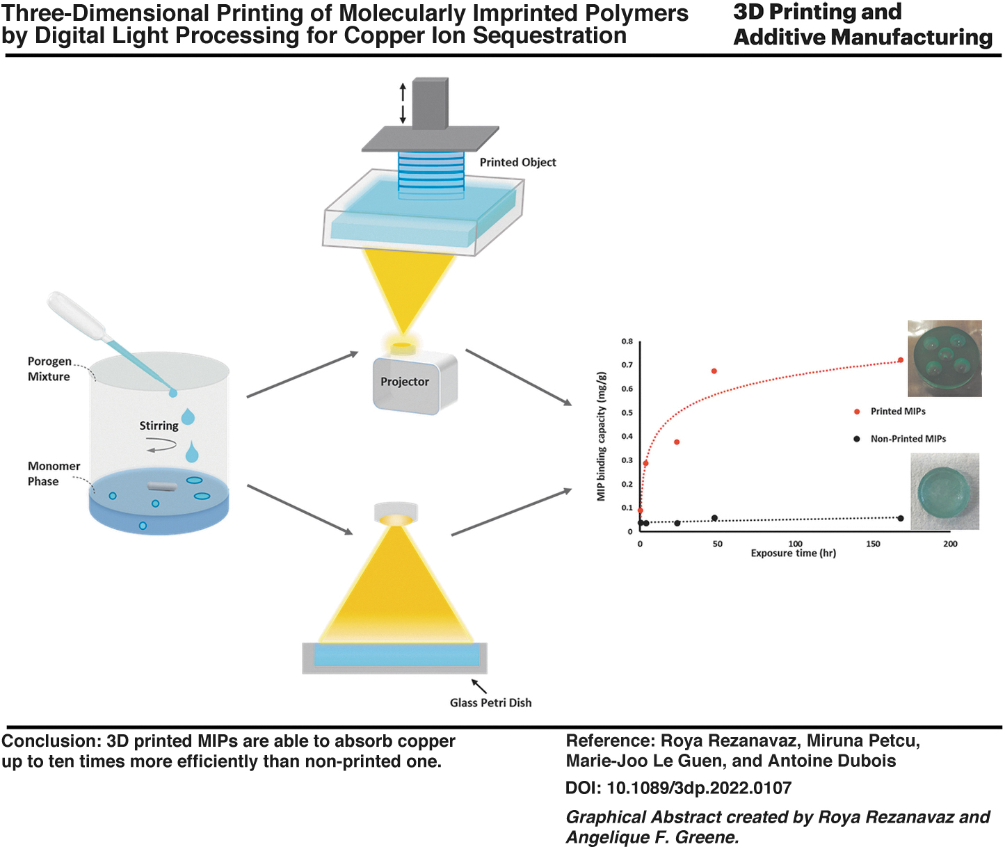
Highly structured, molecularly imprinted polymer (MIP) networks for copper(II) ion sequestration have been realized using the additive manufacturing technology. Photopolymerizable formulations with acrylic functional monomers and two different porogens (water and methanol) in different ratios were studied to produce emulsions with 50 vol% of the internal phase. The results of morphological characterization indicate that all MIPs have cauliflower-like multiscale structures that change as a function of the solvent combination and fabrication process. X-ray fluorescence microscopy maps presented a layered structure and homogeneous distribution of copper in the printed MIP. Copper(II) ion adsorption–desorption tests were performed on MIPs prepared using a three-dimensional (3D) printing approach and MIPs prepared by bulk polymerization. Results indicate that the 3D printed MIP is able to absorb copper up to ten times more efficiently than the nonprinted one and the printed MIP with 100% water content has the highest imprint recognition.
Introduction
Molecularly imprinted polymers (MIPs) are polymers containing cavities specific to molecules that are designed to recognize (template). MIPs are typically synthesized by copolymerization of functional monomers, cross-linkers, and the target molecule, all of which are dissolved in a solvent (porogen). The porogen plays a dual role: it enables the template and monomers to solubilize and interact and it also generates a porous structure upon polymerization.
A porous structure is required to enable access to active cavities containing the target analyte. Upon extraction of the template, empty binding sites that are complementary in structure and function to the template are generated in the polymeric structure.1–4 MIPs can be prepared for a wide range of molecules depending on the application area. They have been in use in chemical separation, catalysis, sensor technologies, and slow-release devices for drugs.5–14
Most of the applications of MIPs have been in separation and recognition of organic molecules.15–18 Studies on MIP metal recognition and sequestration have been increasing over the years 19 both for detection and removal of metals, with applications ranging from environmental cleanup to impurity purification and extending to green separation of chemically similar metal ions from a hard-to-purify metal stream (e.g., rare earth elements). Metal ion sequestration using MIPs offers countless possibilities.20,21
However, one of the key limitations in the practical application of MIPs is their undefined architecture.22–25 This is particularly a problem in the case of metal ions, with an angstrom-sized ionic radius, where well-defined active cavity shape and size are crucial. The application of additive manufacturing (AM) technologies in production of MIPs provides an ideal approach for generating a well-defined three-dimensional (3D) object that retains all attributes necessary for target recognition.25,26
AM, colloquially known as 3D printing, is an attractive technology owing to its ability to generate a variety of macrostructured architectures. Among the AM technologies that build complex 3D objects by layer-upon-layer addition of material,27–29 one commonly used AM method is vat polymerization.30–34 This technology uses resins that are cured in situ through a range of initiation methods, generating a highly organized polymeric structure. The similarity in composition of polymerization media makes it highly amenable to application in MIPs.
Although conventional MIP synthesis would be perceived as more cost-efficient, since it does not require expensive 3D printing equipment, the inconsistencies in small-scale polymerization processes can lead to polymer activity and material losses. A highly organized 3D structure, highly amenable to a filter structure and capable of handling high volumes and turbulent flows, can only be achieved through 3D printing rather than filter packaging with conventionally produced MIPs.
The fabrication of high-resolution 3D MIPs using various printing methods (such as microcontact printing [soft lithography], microscale stereolithography [μSLA], and two-photon stereolithography [TPS]) has been reported.22,23,35 A comparison of these printing methods is shown in Table 1.33,34 Conard et al. 22 used μSL to print 3D microstructures with adenine recognition sites. Gomez et al. 23 developed an MIP formulation compatible with TPS, a microfabrication technique that enables the perfect replication of miniaturized 3D objects at the micro- and nanoscale to fabricate a chemical microsensor with a high-resolution 3D structure. They showed that the polymerization conditions used in TPS preserve molecular recognition and improve the binding capacity of resulting MIPs.
Comparison of Three Different Printing Methods
3D, three-dimensional; DLP, digital light processing; μSLA, microscale stereolithography; TPS, two-photon stereolithography.
Spangenberg et al. 35 prepared 3D structures with submicrometric resolution of MIPs with one or several types of imprints using TPS. TPS can build objects with high resolution; however, the maximum build size obtained by this method is ∼100 nm, which makes it unsuitable for larger-scale MIP synthesis. μSL is used to generate larger structures, but one of its main disadvantages is its limited printing speed.
In the case of a larger MIP structure printable using μSL, formation of the template–functional monomer complex has changed dramatically over time. This was expected to lead to inconsistent MIP formation. Therefore, a suitable 3D printing technique that can rapidly and efficiently fabricate MIPs with complex architectures must be developed.
There are no reports describing the 3D structuring of MIPs using digital light processing (DLP). In contrast to stereolithography, which primarily uses UV lasers as a light source, DLP utilizes a digital micromirror device (DMD) to project patterns with a resolution of up to 3–4 μm onto a photoresist layer and selectively polymerizes individual pixels within a thin layer.
Several hundred thousand microscopic mirrors arranged in a rectangular array on the surface of a DMD chip corresponded to the pixels in the image to be displayed. The use of DMD in DLP promotes rapid cross-linking in a complete layer instead of a single dot in stereolithography (SLA), significantly accelerating the formation of larger structures. 28
In this study, Cu-MIPs were prepared using conventional bulk polymerization and DLP printing. The effects of (1) the 3D printing process and (2) different porogenic solvents were studied for a hybrid polymerization mixture designed to accommodate both DLP and MIP.
Experimental Analysis
Materials
Tetraethylene glycol diacrylate (TEGDA), ethylene glycol dimethacrylate (EGDMA), poly(ethylene oxide)-b-poly(propylene oxide)-β-poly(ethylene oxide) (PEO-PPO-PEO, Pluronic® L-81), diphenyl(2,4,6-trimethylbenzoyl)phosphine oxide/2-hydroxy-2-methylpropiophenone, blend, methacrylic acid (MAA), ammonia 28% solution, and formic acid (FA) were purchased from Sigma-Aldrich (St. Louis, MO). TEDGA and EGDMA were purified over basic Al2O3 to remove inhibitors before use.
Milli-Q-grade water was used for all experiments. Methanol, sodium hydroxide (NaOH), and copper(II) sulfate hydrate were purchased from Merck (Kenilworth, NJ) and used as received.
Physicochemical characterization
MIP synthesis
The MIP was prepared using five different porogen mixtures in triplicate, as summarized in Table 1. Porogen mixtures for the MIPs were prepared using 50 mg/mL copper(II) sulfate solutions in methanol/water mixtures with different ratios. The porogen mixtures for the reference polymers contained only methanol/water in the same ratios as the MIPs, with no addition of copper. The continuous nonpolar phase formulation, comprising TEGDA (1.1 mL), EGDMA (0.55 mL), MAA (38 μL), surfactant (Pluronic L-81, 0.5 mL), and initiator [diphenyl (2,4,6-trimethylbenzoyl)phosphine oxide/2-hydroxy-2-methylpropiophenone, blend, 0.2 mL], was mixed in a 50-mL flask using a stirrer bar. The porogen mixture solution (3 mL) was then added dropwise under constant stirring at 200–250 rpm. After the addition was completed, stirring was continued (10 min) to ensure complete mixing.
For the printed MIPs, the solution was removed from the flask and transferred to a 3D printer bath. A DLP Kudo Titan 2 (Kudo3D, Dublin, CA) containing a broadband white light projector with an intensity of 3000 lumens was used for printing the prepared mixtures. The mixture was printed using a simple disk-like design .stl file with 50 layers (each layer 50 μm). The exposure time for each layer was kept constant at 20 s. For nonprinted MIPs, the solution obtained was transferred from the flask into a glass Petri dish and placed for 10 min under UV curing light.
The resultant polymers were washed several times to remove the target analytes. Therefore, the polymers were stirred in 30 mL of MQ water for 10 min in a 100-mL beaker and filtered with a filter paper (Whatman™, 110 mm diameter, hardened, ashless filter paper). The solids were air-dried and then washed in 20 mL of 10% FA in MeOH solution, stirred for 10 min, filtered, and air-dried again. This process was continued by washing with 20 mL of 1 M NaOH solution, 20 mL of 10% FA in MeOH solution, 20 mL of 1 M NaOH solution, 15 mL of 10% ammonia solution, 30 mL of Milli-Q water, and 30 mL of Milli-Q water. The cleaned polymers were dried in a vacuum oven at 40°C before characterization and use.
Physical characterization
The morphological features of the printed MIPs were investigated using a field emission scanning electron microscope (FESEM) using a JEOL JSM-6700 F instrument (Jeol Ltd., Tokyo, Japan). The cross-section cut of the samples was coated with chromium and viewed at an accelerating voltage of 5 kV for secondary electron detection.
The X-ray fluorescence microscopy (XFM) experiments were performed at The Australian Synchrotron (Melbourne, Australia). The samples were cut with a razor blade, sanded using a Mecapol P230 polishing machine (Presi, France) with 2000 grit sandpaper at 20 rpm, and held in place with Kapton tape. The samples were then mounted on an XFM sample plate. Incident energy of 12.9 keV was used. The high-resolution samples (2 μm) were plotted and acquired. Elemental distribution maps were produced using the GeoPIXE software on the Australian Synchrotron Compute Infrastructure.
An inductively coupled plasma mass spectrometer (ICP-MS) (PerkinElmer NexION, Akron, Ohio) was used to determine the copper concentration in the filtrates from the washing steps and binding studies.
Binding capacity of the MIP
Static adsorption of MIPs was carried out according to the following procedure. Briefly, the weighed MIPs (printed disks or the corresponding amount of bulk synthesized MIPs) were placed in contact with 10 mL of copper solution in water (concentrations of 5, 10, 25, 50, and 100 mg/L Cu), and aliquots were taken at specified times at 30 min, 4, 24, 48, 72, and 168 h. Measurement of depletion of the target ion from the solution was performed in triplicate using ICP-MS analysis.
The binding capacity of the MIP was calculated by Equation (1):
where Q is the binding capacity (mg/g), C0 is the initial copper concentration (μg/mL), Ct is the concentration of copper at time t (μg/mL), V is the volume of the initial copper solution (mL), and m is the mass of the MIP (mg).
Results and Discussion
Polymer synthesis
Acrylate-based monomers and cross-linkers were selected for MIP synthesis and printing as they have been shown to work with both techniques. Copper(II) sulfate pentahydrate [CuSO4·5 H2O] was insoluble in most organic solvents suited for the monomeric phase in the chosen formulation. However, it is highly soluble in water and methanol (156 g/L).
Mixtures of water and methanol were investigated the same way as the porogens. Pluronic L-81 with a low hydrophile–lipophile balance value was added to all mixtures to reduce the interfacial tension between the two phases and increase emulsion stability. MIPs were synthesized using both 3D printing and a conventional polymerization (bulk) approach to assess the binding activity and morphological changes caused by the printing process.
The formulations presented in Table 2 were prepared and then photopolymerized by exposure to UV-Vis radiation on the benchtop for nonprinted MIPs and layer-by-layer for printed MIPs. The 3D models of MIPs with the desired structures were designed using SolidWorks 2019 (SolidWorks Corp., Waltham, MA) and converted into a stereolithography (.stl) file format. Subsequently, the 3D models were sliced by the Creation Workshop to generate digital patterns for 3D printing.
Compositions of Printed and Nonprinted Molecularly Imprinted Polymers
All MIPs prepared using EGDMA (1.1 mL), TEGDMA (0.55 mL), MAA (38 μL), Pluronic L-81 (0.5 mL), and photoinitiator (0.2 mL).
EGDMA, ethylene glycol dimethacrylate; MAA, methacrylic acid; MIPs, molecularly imprinted polymers; TEGDA, tetraethylene glycol diacrylate.
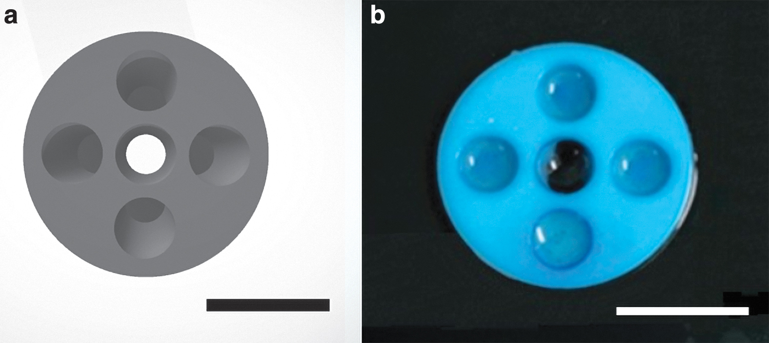
A disk-shaped design was used in a previous study (.stl format), and 3D printed MIP disks of 10 mm diameter and 2 mm height were obtained (Fig. 1). These were washed to remove the copper template, according to the procedure described in the Methods section.
Copper distribution
XFM was used to investigate the copper distribution within the layering of the printed MIP. For this purpose, a sample with 25% MeOH was printed in 100 layers using a disk-shaped design in the .stl format with a 10 mm diameter and 5 mm height. As phase separation was observed after printing 50 layers of the emulsion, a fresh emulsion was injected (Fig. 2a). The Compton scatter distribution in Figure 2b presents the “soft matter” density distribution and distinctive layered structure of the printed MIP.
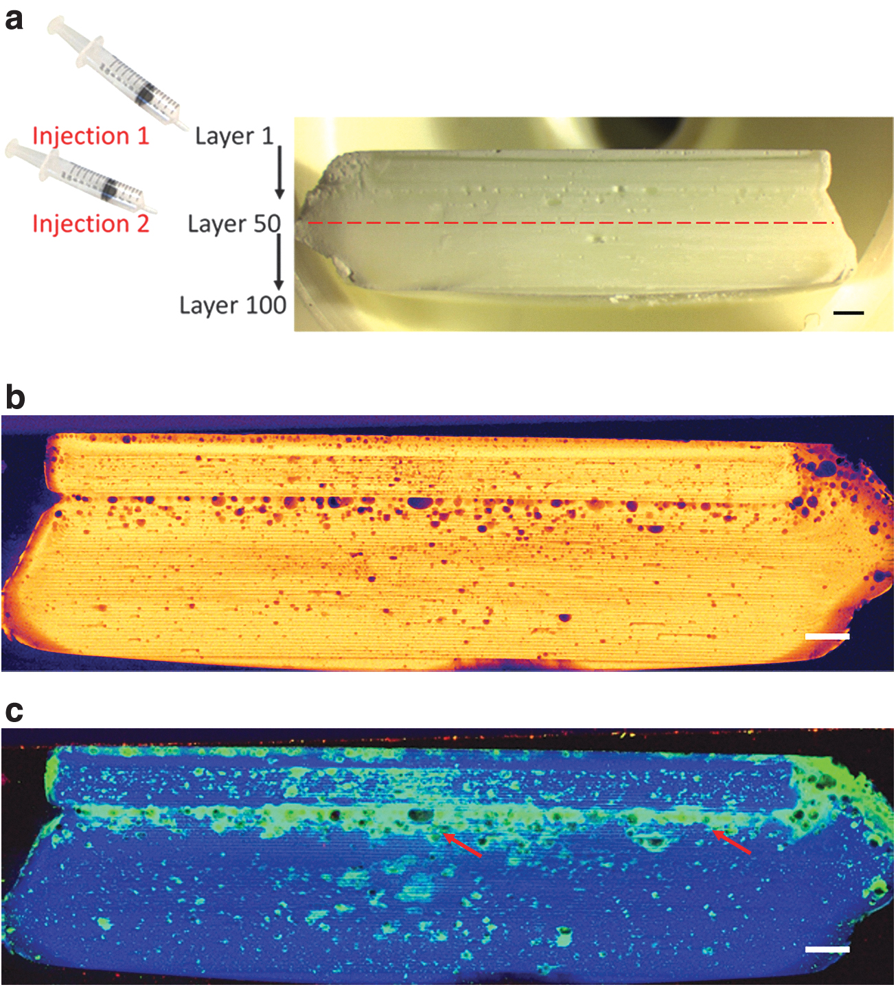
In addition, overcuring was observed in the sections at the edge of the disk. This is caused by light scattering during printing owing to water droplets present in the emulsion mixture, especially after printing the first 50 layers. The copper and Compton distributions are presented in Figure 2c. This indicates the presence of copper in the whole sample.
Agglomeration of copper can be seen and appears to present with phase separation at some locations. Based on these observations, it was decided to print all MIPs for further experiments in only 50 layers to avoid any side effects of phase separation and light scattering.
MIP morphology and binding capacity
FESEM was used to visualize the influence of the solvent mixtures and to compare the morphologies of MIPs obtained using the two different manufacturing techniques. In addition, adsorption isotherms of the MIPs were obtained by adding a given number of copper(II) ions to a given amount of MIP, as mentioned in the Methods section. Figure 3 shows a comparison between the morphologies and adsorption isotherms of printed and nonprinted MIPs with different porogenic mixtures.
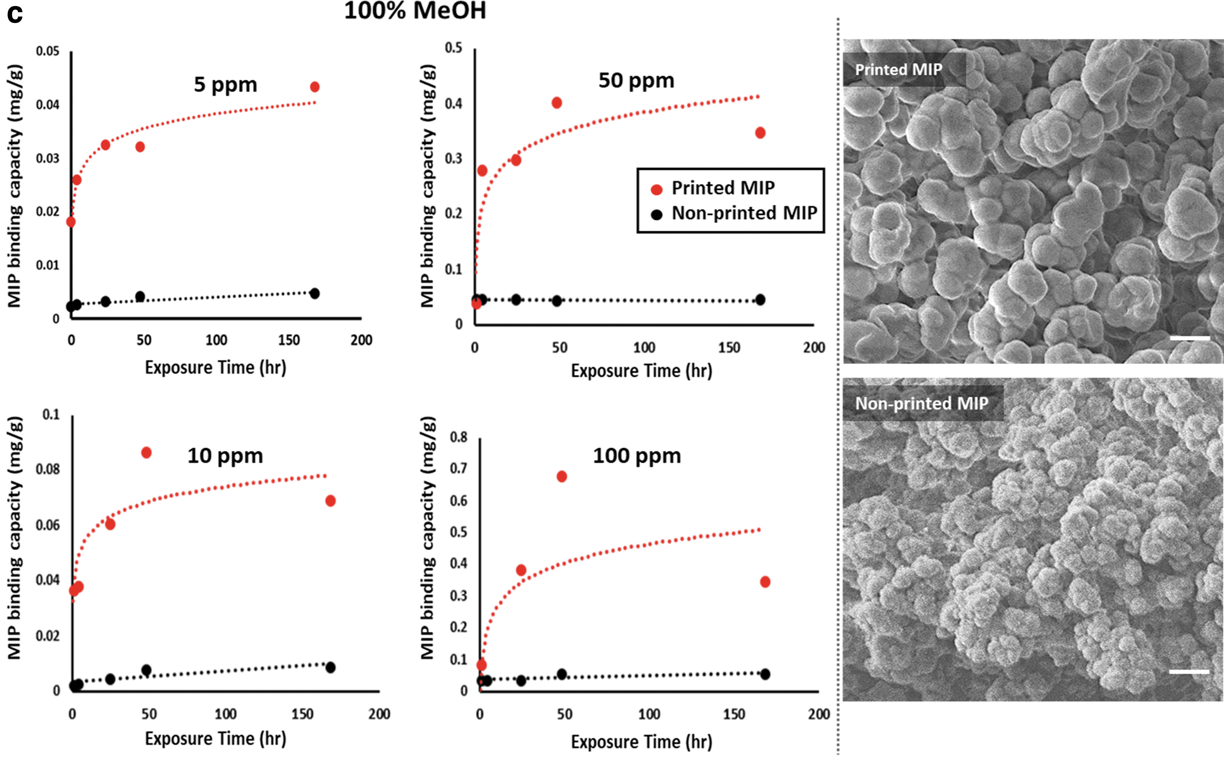
The adsorption isotherm curves and FESEM images of the printed (red marks and line) and nonprinted (black marks and line) MIPs with different methanol/water ratios in the porogen mixture:
The scanning electron microscope (SEM) images demonstrate that both water and methanol act as porogens, creating the porous structure that is essential for ease of access to the active sites. A higher amount of water is on one hand associated with formation of meso- and macropores and small surface areas, as observed by others as well. 6 A larger amount of water also induces an early stage phase separation between organic and aqueous phases, leading to more macropores or more heterogeneous material.
Methanol, on the other hand, enables monomer solubilization and hence promotes smaller nuclei and formation of smaller polymer particles, leading to formation of micropores in the polymeric structure.
For a nonprinted MIP produced in methanol–water mixtures, the factors highlighted above would promote macroporosity in 100% water, as seen in Figure 3a. The polymer appears unstructured as the polymerization process occurs simultaneously in the entire mixture. Macroporosity with no organization usually translates into large numbers of bound target molecules, but mostly nonspecific, as templates will nonspecifically stick to the surface of the MIP.
Conversely, 100% methanol in the porogen mixture, promoting microporosity, shows a more well-defined structure of small polymeric particles bound together. This leads to lower binding, mostly specific, due to a higher level of organization of the sites, but with a smaller number of active sites formed.
The printed MIPs show a different morphology with more porosity than the nonprinted ones. With 100% water in the mixture, the polymer comprised small primary particles that are continuously interconnected. With addition of methanol, the primary particles became weakly and hierarchically interconnected, forming a cauliflower-like structure.
The morphology differences between nonprinted and 3D printed polymers can be attributed to faster curing of the resin in each layer in the printing method as well as the difference in evaporation rate between the two solvents. In DLP printing, the polymerization mixture is exposed to light radiation, which leads to localized temperature increases. This results in a higher evaporation rate of methanol, which in turn affects the morphology. Faster evaporation rates will lead to larger nucleus formation than in nonprinted polymers, hence larger microstructures.
Figure 3 also compares the adsorption isotherms of printed MIPs and nonprinted MIPs with different porogenic mixtures (0%, 50%, and 100%) over a period of 168 h (adsorption isotherms of MIPs with 25% and 75% MeOH in progenic mixture are presented in Supplementary Fig. S1). As can be seen, the equilibrium adsorption capacity of MIPs improved dramatically (ca. factor of 10) by printing them. In addition, printed MIPs produced isotherms that can be described by the Langmuir equation (type 1 isotherms).
In contrast, the amount of bound copper remained almost constant over time for nonprinted MIPs, indicating that equilibrium conditions were achieved much faster. Results suggest that the higher specific area of MIPs produced using the printing procedure provides a greater contact area between the MIPs and the solution and better utilization of cavities in the MIPs. This is in line with the results of the structural study of MIPs, which showed that faster curing of each layer in printing increases the size of cauliflower-like structures. This, in turn, results in increased microporosity and a higher binding capacity of MIPs.
Figure 4 shows the amount of copper adsorbed after 168 h in the 100 ppm solution for both printed and nonprinted MIPs synthesized using different water/methanol mixtures. It can be seen that maximum binding capacity decreases slightly with increasing methanol content in the porogenic mixture. The binding capacity depends on many factors, including interactions between the template ion and functional monomers during the polymerization stage and the subsequent availability of specific cavities for interaction with the target template upon rebinding.
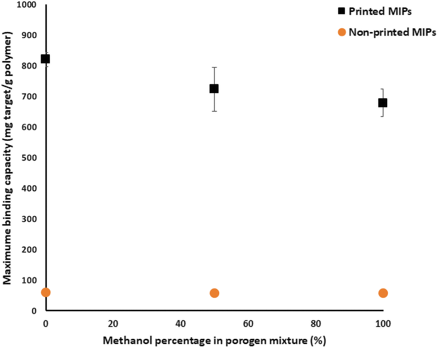
The maximum adsorption capacity of the MIPs at 100 ppm Cu solution.
As discussed earlier, copper salts are soluble in both water and methanol, but monomers are soluble only in methanol; thus, Pluronic L-81 was added as an emulsifier. However, the mixture is metastable and a preferential distribution of the template in water, when available, and the monomers in methanol will likely occur. The imprinting ability is known to decrease with polarity and H-bonding ability of the porogen. 37 Increased H-bonding capability and solubility result in macropore formation, which is usually associated with increased binding ability of the resulting material, but in a nonspecific manner.
Moreover, in most metastable systems, when no methanol is present, there are fewer interactions between the template and the monomer mixture, resulting in both increased macroporosity and fewer specific sites being formed. In line with this, it can be observed in Figure 4 that the maximum binding capacity was found in this solvent system, but it was mainly nonspecific binding.
When no water was used in the polymerization mixture, all the copper was in contact with the monomer mixture, leading to formation of the maximum number of specific sites. Although the overall binding is smaller than that in the water polymer, most of it is specific binding, and an equilibrium plateau is reached.
Conclusions
It has been demonstrated that an emulsion templating approach can be used in combination with an AM technique to fabricate 3D microstructured MIPs capable of recognizing a metal imprint analyte. Printing leads to a dramatic increase in the binding capacity of MIPs compared with MIPs fabricated by conventional bulk polymerization. This is related to the ability of AM to generate highly microporous structures with very short polymerization times.
Studies on the effect of porogen composition and template–monomer interactions were performed in both conventional and printed polymers, and the results showed a slightly increased capacity when water was present, while still highlighting the presence of active sites. The emulsion templating and 3D printing processes resulted in a better binding interaction of the imprinted microstructure than for materials prepared using solvents or bulk polymerization.
This hybrid technique presents new options for the synthesis of MIPs for metal sequestration.
Footnotes
Acknowledgments
The authors wish to acknowledge the helpful contributions of Dr. Kendra Newick, Dr. Hamish Pearson, Dr. Angelique F. Greene, and Dr. Robert Abbel.
Authors' Contributions
R.R. was involved in conceptualization, methodology, investigating, and writing—original draft preparation. M.P. was involved in formal analysis, data curation, and writing—review and editing. M.-J.L.D. was involved in supervision, funding acquisition, and writing—review and editing. A.D. was involved in investigation.
Data Availability
The raw/processed data required to reproduce these findings cannot be shared at this time as the data also form part of an ongoing study.
Ethical Compliance
All procedures performed in this study involving human participants were in accordance with the ethical standards of the institutional and/or national research committee and with the 1964 Helsinki Declaration and its later amendments or comparable ethical standards.
Author Disclosure Statement
No competing financial interests exist.
Funding Information
This work was funded by the Ministry of Business, Innovation, and Employment Smart Ideas, Grant number C04X1706-Water and Toxic Metals.
References
Supplementary Material
Please find the following supplemental material available below.
For Open Access articles published under a Creative Commons License, all supplemental material carries the same license as the article it is associated with.
For non-Open Access articles published, all supplemental material carries a non-exclusive license, and permission requests for re-use of supplemental material or any part of supplemental material shall be sent directly to the copyright owner as specified in the copyright notice associated with the article.