
Abstract
Single-step 3D printing, which can manufacture complicated designs without assembly, has the potential to completely change our design perspective, and how 3D printing products, rather than printing static components, ready-to-use movable mechanisms become a reality. Existing 3D printing solutions are challenged by precision limitations, and cannot directly produce tightly mated moving surfaces. Therefore, joints must be designed with a sufficient gap between the components, resulting in joints and other mechanisms with imprecise motion. In this study, we propose a bio-inspired printable joint and apply it to a Single sTep 3D-printed Prosthetic hand (ST3P hand). We simulate the anatomical structure of the human finger joint and implement a cam effect that changed the distance between the contact surfaces through the elastic bending of the ligaments as the joint flexed. This bio-inspired design allows the joint to be single-step 3D printed and provides precise motion. The bio-inspired printable joint makes it possible for the ST3P hand to be designed as a lightweight (∼255 g), low-cost (∼$500) monolithic structure with nine finger joints and manufactured via single-step 3D printing. The ST3P hand takes ∼6 min to assemble, which is approximately one-tenth the assembly time of open-source 3D printed prostheses. The hand can perform basic hand tasks of activities of daily living by providing a pulling force of 48 N and grasp strength of 20 N. The simple manufacturing of the ST3P hand could help us take one step closer to realizing fully customized robotic prosthetic hands at low cost and effort.
Introduction
Robotic prosthetic hands hold great promise for improving the quality of life by restoring high levels of hand function; therefore, they have been studied over several decades to improve users' quality of life. Recent research topics on prosthetic hands range from biomimetic or bio-inspired design, dexterous grasping capabilities,1–4 a sense of touch restoration, 5 and intuitive control strategies via user intention detection and sensory feedback.6–11 Meanwhile, commercial prosthetic hands have been focusing on their practicality such as an anthropomorphic appearance with individually actuated fingers and an opposable thumb, capable of making various postures and grasping different objects robustly.12–14 However, the technological advances in recent studies and state-of-the-art commercial robotic prosthetic hands do not seem to provide a distinct general advantage over body-powered or cosmetic prostheses in performing activities of daily living (ADLs). 15
One example can be found in the powered arm prosthetic race of Cybathlon in 2020; a participant with a simple four-fingered, body-powered prosthesis won first place by performing a series of tasks faster and more accurately than others with sophisticated robotic hands.16–18 In fact, many hand amputees still rely on cosmetic or body-powered prosthetic hands rather than sophisticated robotic hands. One of the major factors contributing to the low acceptance rate of a robotic prosthetic hand, among other factors including a lack of sensory feedback and unnatural movements, is an insignificant functional advantage compared with its weight and cost.15,19
One way to reduce the weight and cost of a robotic prosthetic hand without functional degradation is to simplify the structural design of the multi-articulated mechanism. Implementing numerous finger joints in a prosthetic hand enables replicating the appearance and movements of the human hand, but, in turn, involves a complicated manufacturing process, increasing the cost and weight of the prosthetic hand. 12 As an alternative to mechanical joints, the compliance of soft structures has been utilized in prosthetics. Fabricated as monolithic structures, soft fingers or hands reduce the weight of the overall system, enable adaptive grasps, and provide simplicity of control.20–30
However, it is difficult for compliant joints to deliver the large range of motion required for a prosthetic finger or to withstand compressive loads because of the risk of plastic deformation.31,32 Another approach for simplifying the structural design of a multi-articulated mechanism is to utilize a 3D-printed, preassembled joint.33–36 Examples of so-called single-step 3D printable or nonassembly mechanisms that consist of 3D-printed, preassembled joints demonstrate the potential of fully autonomous robot manufacturing without an assembly process. By removing the components for joint assembly, such as bolts and bearings, a single-step 3D printing approach and its enabling design can reduce the weight and cost of the overall system.
However, the performance of existing single-step 3D printable mechanisms33–39 is insufficient for applications that require precise transmission of force and displacement. This is mainly owing to the characteristics of 3D printing, such as rough surfaces and undesired fusion between thin gaps.40–47 In traditional manufacturing processes, the pin and hole of a revolute joint are tightly mated using an assembly to provide precise rotational movement. However, when using single-step 3D printing, an appropriate gap size between the pin and hole should be designed to prevent undesired fusion. This sub-millimeter gap enables relative motion between the pin and hole; however, in return, it causes wobbling during joint movement.48–55 Although attempts have been made to reduce the gap by changing the geometries of the pin and hole of the joint, a wobbling issue still exists.56,57
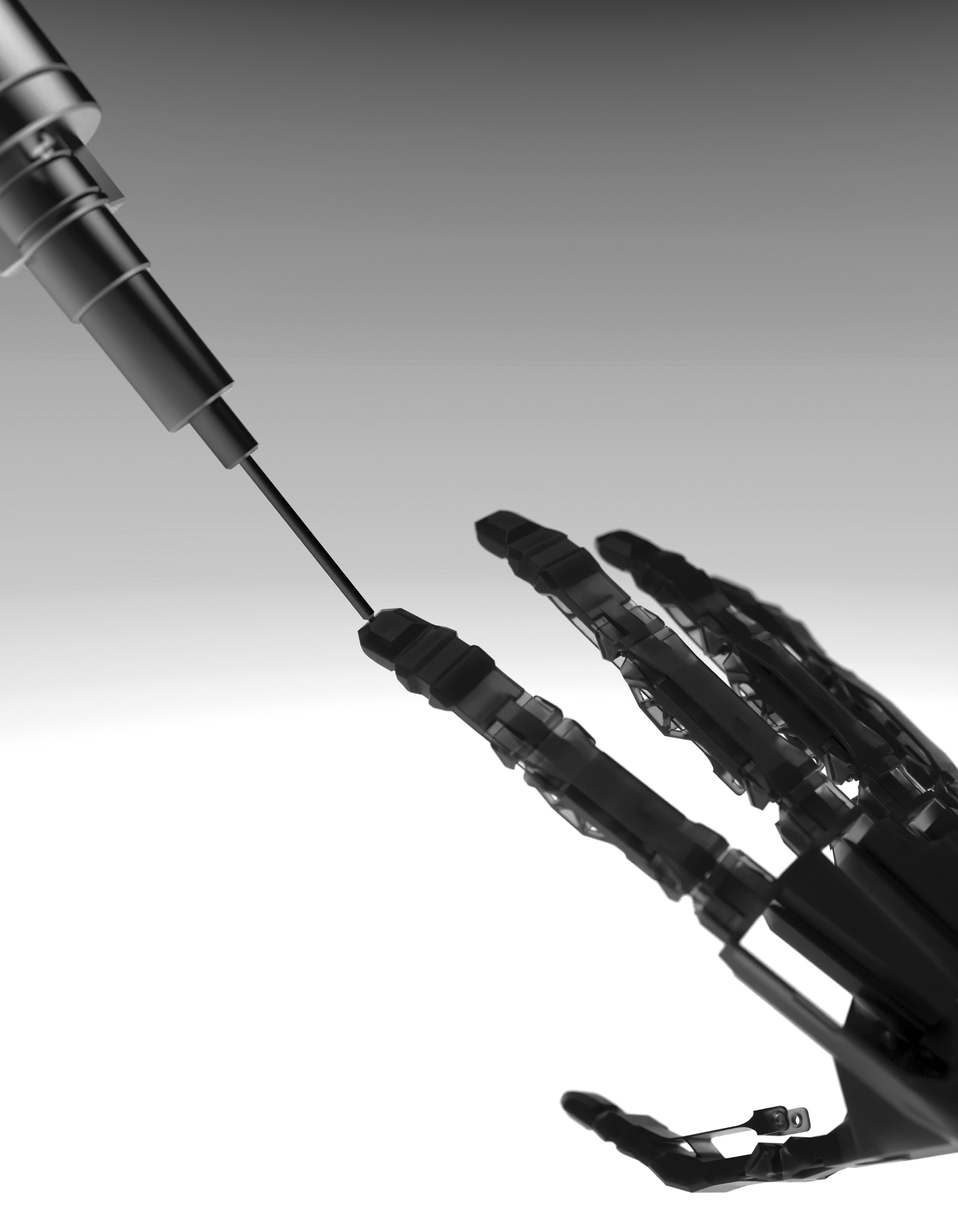
We propose a bio-inspired 3D printable joint that can be manufactured via single-step 3D printing and generates precise joint motion (Fig. 1). Inspired by the manner in which the cam effect works in human finger joints,58–60 the joint was designed such that the gap changes as the joint bends. The joint exhibits a gap in the initial state, which is crucial for successful 3D printing and support removal. After printing, the gap was closed to ensure contact with the surface. Surface contact adds kinematic constraints to the joint, allowing for precise flexion and extension movements. The maximum allowable external moments for the proposed joint in the lateral and frontal directions were measured to be ∼328 and 373 Nmm, respectively.

Design and manufacturing process of the ST3P hand.
A periodic flexion–extension movement test demonstrated that the joint could withstand loads for 50,000 cycles exhibiting a robust fatigue life. We used this bio-inspired printable joint to create a Single-sTep 3D-printed Prosthetic hand (ST3P hand). The bio-inspired printable joint makes it possible for the finger joints, tendons, and palm of the ST3P hand to be designed as a monolithic structure that can be 3D printed in a single step without assembly. The ST3P hand is produced by 3D printing the structure, inserting actuators and electronics, and connecting the power source. The time required for assembly is approximately one-tenth that of open-source 3D printed prostheses.38,39 The simplified assembly helps the ST3P hand to keep the price as low as possible so that people who actually need them can afford it.
The estimated total cost of a single ST3P hand was less than $500. To verify the mechanical characteristics of the ST3P hand, we performed several types of grasping tests including power, pinch, and object grasping. The test showed that the ST3P hand was capable of providing a pulling force of 48 N and a grasp strength of 20 N and successfully grasped multiple objects. We also propose various examples of single-step 3D-printed mechanisms designed by integrating bio-inspired printable joints (Fig. 2). We anticipate that our bio-inspired printable joint design and ST3P hand will become an example that enable the design and production of other customized prosthetic hands tailored to an ever-growing set of user requirements at low cost and effort.
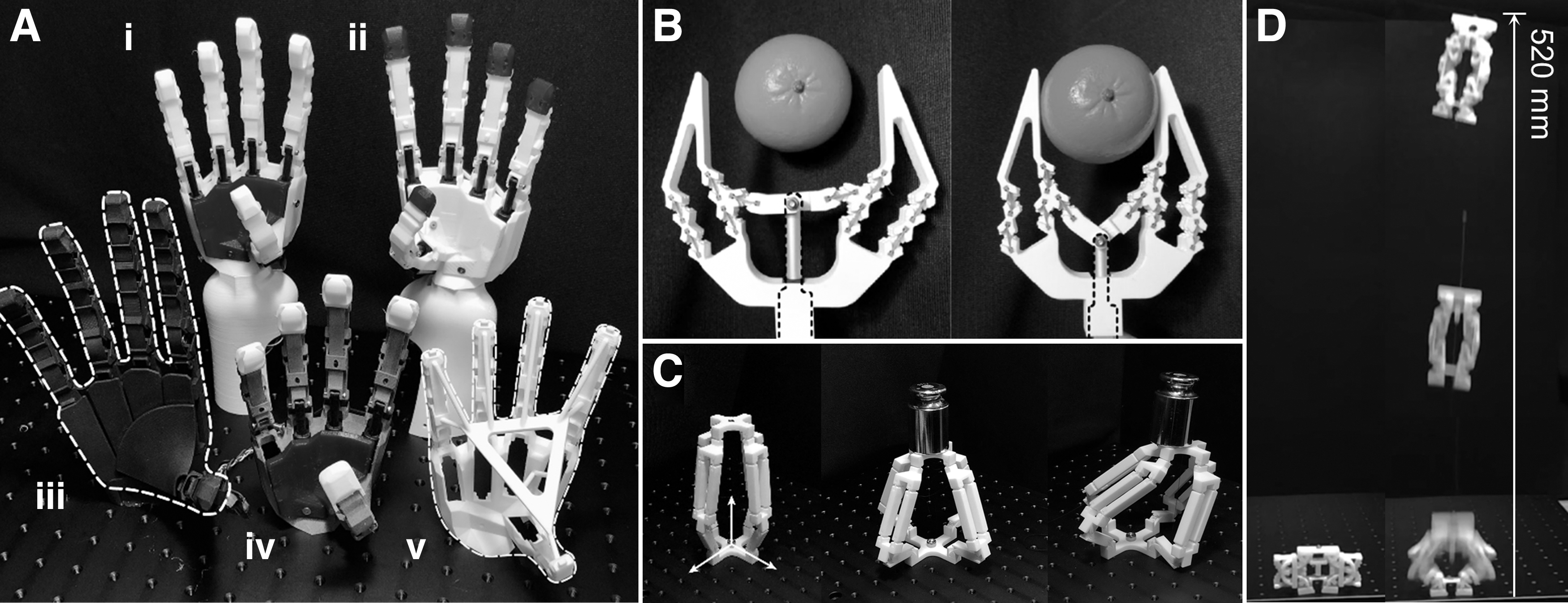
Examples of mechanisms that composed of the bio-inspired printable joints. Different 3D printing techniques and materials are used to manufacture various mechanisms to check the potential of the proposed joint design. All structures are manufactured through single-step 3D printing and actuators and electronic components were manually assembled.
Materials and Methods
Bio-inspired printable joint
The bio-inspired printable joint was designed as a monolithic structure consisting of a ligament, two cam surfaces, and two articulated surfaces (Fig. 1B). The ligament is a deformable, thin cantilever beam that generates the flexion and extension motions of the joint, whereas the cam and articulated surfaces, which are designed to be rigid, impose appropriate constraints on ligament deformation.
One of the main functions of the cam effect in the metacarpophalangeal (MCP) joint of the human hand is a change in the length of the collateral ligament (Fig. 1A).58–60 When the joint angle increases, the ligament elongates and deforms as it is wound around the metacarpal head. Ligament elongation increases the internal contact force between the two bones, the metacarpal bone and the proximal phalanx, making the joint more stable. Conversely, the cam effect of the bio-inspired printable joint is designed not to cause ligament elongation but instead to reduce the gap between the articulated surfaces. There was a sufficient gap between the two articulated surfaces in the initial state of the joint. As the joint angle increases, the ligament is wound around the cam surfaces, the gap between the articulated surfaces gradually closes, and the articulated surfaces come into contact with each other. Based on whether there is contact between the articulated surfaces, two different states of the joint are defined: the postprinted state without contact and the functional state with contact. The gap in the postprinted state enables single-step 3D printing of the joint, preventing undesired material fusion between surfaces, and allowing the successful removal of support materials after 3D printing. Contact of the joint in the functional state imposes additional kinematic constraints on the joint, leading to precise flexion and extension motions (Fig. 1B).
Correlation between gap and involute curves
To realize the bio-inspired cam effect with single-step 3D printing, the correlation between the gap as a function of the joint angle and the design of two governing curves (i.e., the outer shape of the cam and the articulated surface) can be designed by satisfying two conditions. First, the gap at the zero joint angle must be sufficiently large for successful printing. Second, for any joint angle from the critical angle in which the state of the joint changes from one to the other, the size of the gap between articulated surfaces should be zero to provide precise flexion and extension. The parasitic motion of the joint can be restricted only when the articulated surfaces remain in contact. Thus, the designed gap starts with a positive value (greater than the minimum size of the printable gap) at the initial joint angle, decreases to zero as it reaches the critical angle, and remains zero from the critical angle to the maximum angle.
The size of the gap g (θ) at the joint angle θ can be expressed as a function of the geometric features, including the ligament and cam articulated surfaces [Eq. (1)], where L is the length of the ligament and Cc and Ca are the parametric representations of the curve of the cam and articulated surface, respectively. A schematic of the joint design is given in Figure 5A. Equations (2) and (3) represent the conditions required for the gap. The joint angle in the functional state, θf, ranges from the critical angle θc, to the maximum angle θm. The gP is the minimum printable gap size.
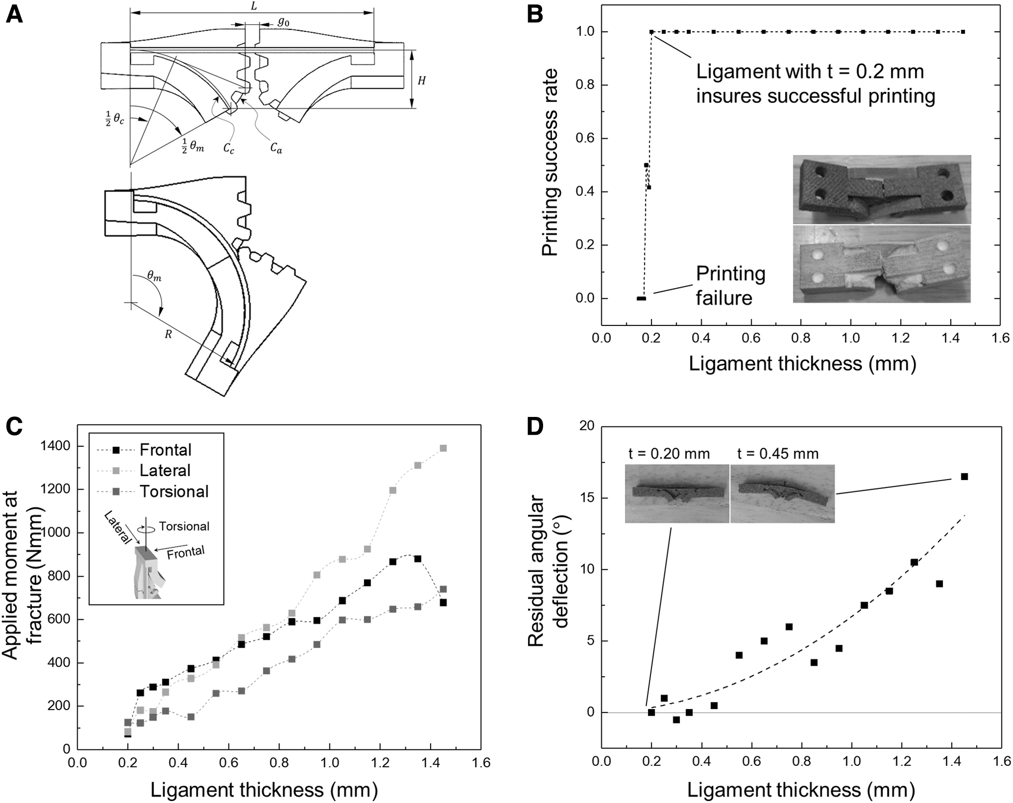
Bio-inspired printable joint characteristics.
To obtain a detailed design of the joint that satisfies the aforementioned conditions, we introduce an involute curve to generate the design of the articulated surfaces. The involute articulated surface ensures that the joint always has a certain gap size, thereby simplifying the joint design problem. 61 Based on the characteristics of the involute curve, the design of the appropriate gap, articulated, and cam surfaces is derived, as given in Figure 3. First, the articulated surface was designed as an involute of the cam surface and a taut strap was fixed to the cam surface at one end and to the ground at the other end. The cam surface was designed as a circle with radius to simplify the joint design. The mathematical property of an involute curve ensures that the articulated surface is always in contact with the ground, regardless of the rotation of the structure. Second, by reflecting such a structure through a plane, a design of a symmetrical structure connected by a strap is obtained. Because each articulated surface meets the plane of symmetry, the two articulated surfaces are in contact with each other. Both the left and right structures had independent rotational degrees of freedom. The gear teeth were designed along articulated surfaces to prevent slippage (Supplementary Fig. S1). The joint design was completed by assigning an appropriate thickness to the strap and cutting a certain portion of the articulated surface such that there was a sufficient initial gap between the articulated surfaces. Detailed analyses of the design parameters, particularly the range of motion of the joint, and the design of the joint to be used in the ST3P hand can be found in Supplementary Note S3, Supplementary Figures S6 and S7.

Bio-inspired printable joint concept. The design of the joint is derived based on the characteristics of the involute curve.
Ligament design
The ligament is a part of the joint that undergoes elastic deformation during joint motion. The ligament is a beam shape with a rectangular cross-section of thickness t, width w, and length L. Among the parameters, we focused on investigating the appropriate ligament thickness because it significantly affects the joint robustness against external loads and durability during repeated use. Thin ligaments cannot withstand large external loads and are more likely to fracture when interacting with the environment. Conversely, thick ligaments may undergo plastic deformation during bending and may degrade after repeated flexion motions. Changes in width and length also influence the deformation behavior of ligaments, but the design space of these parameters is relatively narrow compared with the case of thickness.
The length is determined according to the design of the gap and articulated surfaces, and the width of the ligament is given as large as possible, considering the width of the actual human finger. Through mechanical model-based analysis (Supplementary Note S1) and experiments, the ligament thickness was designed to be 0.45 mm. The final design of the joint for the ST3P hand has a ligament of 0.45 mm thick and 20.94 mm long, an initial gap of 0.28 mm, a joint height of 5 mm, and a maximum joint angle of 120°.
Design of the ST3P hand
As a representative example of a single-step 3D printable mechanism using bio-inspired printable joints, the ST3P hand was designed (Fig. 4 and Table 1). The primary goal of the design is to (1) replicate the fundamental structures and essential functions of the human hand62,63 while (2) allow the entire structure, including tendons and sheaths, to be 3D printed in a single step (Supplementary Fig. S4 and Supplementary Note S2). The hand structure is designed by arranging nine bio-inspired printable joints at positions where general human finger joints are located and joining them with rigid links that have the appearance of phalanges and a palm (Supplementary Fig. S2). 64 Each finger has two bio-inspired printable joints at the place of the MCP joint and proximal interphalangeal (PIP) joint. To simplify the design, the distal interphalangeal joints are omitted. The interphalangeal and carpometacarpal joints of the thumb are also omitted; thus, the thumb has one bio-inspired printable joint for flexion and extension.
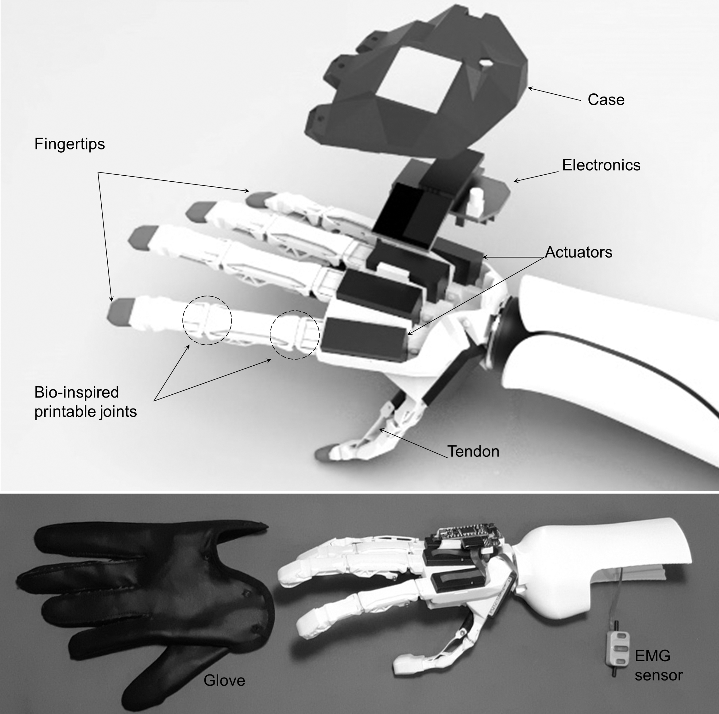
Overall design of the ST3P hand. The entire ST3P hand structure, including the fingers, tendons, and palm, was manufactured using a single-step 3D printing process. Actuators, a microcontroller board (including a small display), and a case are assembled on the dorsal side of the hand. Tendons are attached to the actuators using screws. The fingertips and palm pad (not shown) were separately printed using an FDM printer with thermoplastic polyurethane filament, and assembled. The fabric glove was designed and fabricated with two separate pieces, one for thumb and the other for rest of the hand, so that it is easy to fit into the 3D-printed hand structure. Forearm sleeve and a surface EMG sensor are also integrated into the ST3P hand. EMG, electromyography.
Mechanical Design Parameters for the ST3P Hand
ST3P, Single sTep 3D-printed Prosthetic hand.
Five commercially available linear actuators were implemented at the palm of the hand, each of which drives both the MCP and PIP joints of the fingers or thumb joint. The actuators were position controlled using a microcontroller board housed on the dorsal side of the hand. For intention detection, a surface electromyography sensor detects the muscle activity of a user from the arm stump. 65 The Morse code-like patterns of the sensor signal were used as triggers to select a desired one from multiple preset grasping postures (Supplementary Fig. S5). A small display was installed on the board to allow the user to check the status of the system. To improve the grasping ability of the hand, soft fingertips and palm pads were separately manufactured and assembled on the hand.
3D printing of the ST3P hand
The entire ST3P hand structure, including the fingers, tendons, and palm, was manufactured using a single-step 3D printing process (Figs. 2A and 4). A wide range of combinations of 3D printers and printing materials has been used to build hand structures. We have figured out that selective laser sintering and multi-jet fusion 3D printing processes with their nylon-based materials are best suited for creating a joint.66–75 These combinations produce satisfactory printing results with a high elastic modulus and strain at yield, which is favorable for the articulated surface and ligament of the joint, respectively (Supplementary Fig. S3).
Results and Discussion
Fracture moments and repeatability of the joint
Fracture, bending, and cyclic loading tests were conducted to verify the effects of the different joint ligament thicknesses. Joints of 20 different thicknesses were designed, and three specimens were fabricated for each joint design. The thickness ranges from 0.15 to 1.45 mm, and was set at 0.01 mm intervals from 0.15 to 0.20 mm, 0.05 mm intervals from 0.20 to 0.35 mm, and 0.10 mm intervals from 0.35 to 1.45 mm. Fracture and bending tests were conducted only for the joints that were successfully printed (Fig. 5B). In the fracture test, external moments were applied to the joints in the frontal, lateral, and torsional directions. By gradually increasing the magnitude of the applied moment, the occurrence of ligament fracture was observed, and the magnitude of the moment was measured. This was performed five times for the same ligament thickness and direction. Figure 5C shows the results. Joints with thicker ligaments withstood greater external moments in the frontal and lateral directions. The ligament thickness has a greater impact on the moment in the lateral direction than in the frontal direction; the joint with 1.20 mm thick ligament endures ∼3.2 times the moment in the lateral direction compared with that of the 0.45 mm thick ligament joint.
A bending test was also performed to verify the repeatability of the joint. In the case of a joint in which the ligament is not sufficiently thin, plastic deformation may occur even with a small number of repeated bending. Primary tests were conducted in advance to filter out these cases. For the test, the joint was flexed to a maximum bending angle of 120°, released, and the joint angle was measured. As a result, it can be seen that the residual angle deflection of the joint whose thickness exceeds 0.45 mm is >1° (Fig. 5D). That is, when the residual deflection of 1° is the failure threshold, the maximum ligament thickness without plastic deformation is ∼0.45 mm. To investigate long-term repeatability, a cyclic loading test for the joint with 0.45 mm thick ligament was also performed. While imparting periodic flexion-extension motion to the joint, the point at which ligament fractures occurred and the number of cycles at that point were measured. Testing continued until the joint fractured or the number of cycles reached 50,000. It was checked whether the joint features including the gear teeth and ligament had a visually identifiable level of wear (Supplementary Fig. S8). As a result, no significant wear on gear teeth were observed on the joints after 50,000 cycles loading and unloading other than minor scratches on the gear teeth. In addition, to understand the effect of cyclic loading on the ligament, the fracture characteristics of the ligament during the test were also investigated. The result showed that the yield moment of joint specimens decreased ∼10%, from 413.3 to 368.3 Nmm, after 50,000 cycles of loading.
Easiness of assembly
Replacing traditional multipart prosthetic joints with bio-inspired printable joints remarkably reduces the total number of parts required for the hand and simplifies the hand assembly. To quantitatively evaluate the simplicity of the assembly, the assembly time for the ST3P hand was compared with that of other well-known 3D-printed prosthetic hands, including the Brunel hand 2.0 and Cyborg Beast hand.38,39 These prosthetic hands were chosen because they have comparable specifications with the ST3P hand (Table 2). Each hand was assembled according to the instructions provided by the developers. An experimenter performed the assemblies with sufficient mastery of assembly through repeated prepractice, and the average assembly time for each hand was obtained by repeating the assembly process three times.
Specification Comparison of 3D-Printed Prosthetic Hands
Fixing elements such as bolts/nuts or screws are excluded when counting the number of mechanical components.
Figure 6A and B provides the assembly processes of the hands and the resultant assembly times. Brunel Hand 2.0 is fabricated by mounting motors on the palm of the hand and then assembling wire tendons and finger joints. The Cyborg Beast hand was fabricated by assembling finger joints, passive extender wire tendons, and flexor wire tendons. On the contrary, the assembly process of the ST3P hand involved only a few steps: attaching linear actuators and electronics and connecting the power source (Supplementary Movie S1). The assembly took ∼6 min, only one-tenth of the other prosthetics. The total production time to create a single ST3P hand for one operator using a single 3D printer 58 was estimated to be ∼86 min (80 min for printing and support removal, 6 min for assembly). This efficient manufacturing and assembly process allowed us to rapidly create many prototypes of the ST3P hand with various designs (Fig. 2A).
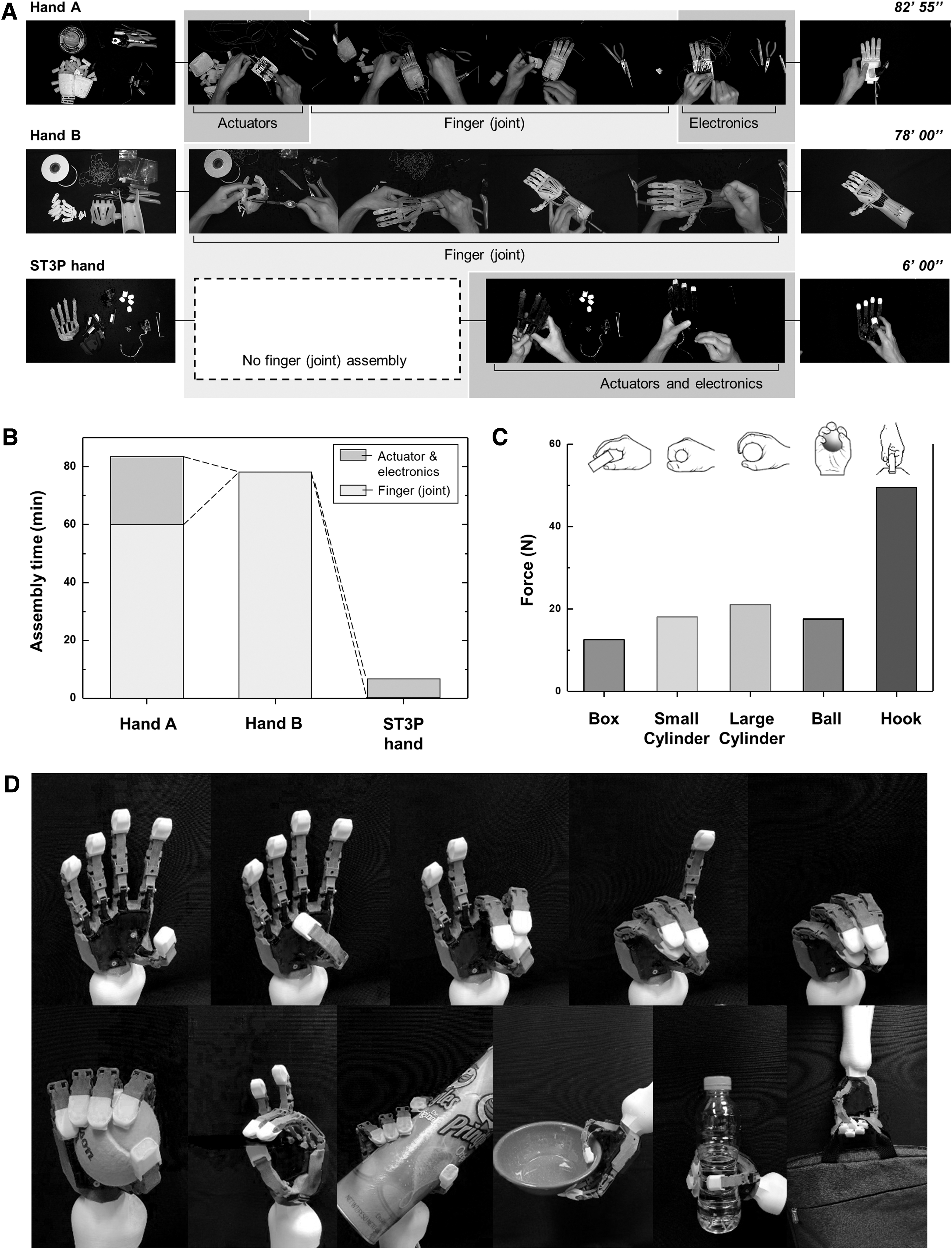
Performance of the ST3P hand.
Hand grasping performance
The final design of the ST3P hand has similar kinematics to those of the human hand, enabling the hand to perform basic tasks for ADLs. The primary ADL task of the hand is to grasp and hold an object with sufficient force using all fingers and thumbs. To demonstrate the grasping performance, sensor-embedded dummy objects and several daily life items (baseball, card, cylindrical box, bowl, plastic bottle, and laptop bag) were used. The dummy object included a rectangular box with a height of 10 mm, a small cylinder with a diameter of 55 mm, a large cylinder with a diameter of 90 mm, and a spherical ball with a diameter of 55 mm. During the ST3P hand grasping of these objects, the pulling force or grasp strength was measured by the embedded load cells. The measured pulling force was 48 N and the grasp strengths was 20 N approximately (Fig. 6C). Grip strength tends to vary considerably depending on the size and shape of the object, owing to the lack of appropriate force feedback control. Figure 6D and Supplementary Movie S2 show that ST3P can take various postures, hold daily items, and interact with the environment (e.g., writing on a tablet using a pen).
Single-step printability and versatility
We have demonstrated that by single-step printing of the ST3P hand, the benefits of 3D printing can be extended from a set of static objects to movable, functional mechanisms. Provided that a 3D printer is available, ST3P hand design can be easily manufactured without specialized skill sets or knowledge. Designers can easily realize customized conceptual designs into physical replications, accelerating the process of design iterations or updates. Prosthetic users can have multiple variations of affordable prosthetic hands that fit their purpose of use, with different esthetics and functionalities, such as housework or sports. Indeed, the concept of single-step 3D printing using bio-inspired printable joints is not limited to prostheses and can be applied to different robotic mechanisms. To explore the potential of single-step 3D printing, three mechanisms, delta, gripper, and jumping mechanism, were designed by integrating bio-inspired printable joints (Fig. 2B–D). 76 Because the bio-inspired printable joint design can minimize the joint gap, unlike other 3D printable joints, a delta mechanism is expected to exhibit an acceptable degree of precision without gap-caused positional errors. The gripper was proposed to explore the compatibility of the proposed joint with a fused deposition modeling-based printing method. The jumper was designed with the use of the joint as an energy storage and release element. The feasibility of each mechanism was tested, as given in Figure 2 and Supplementary Movie S3. Detailed designs of the mechanisms are given in Supplementary Note S4.
Conclusion
We developed a bio-inspired printable joint that resolves the typical problem of 3D printed joints. The existing 3D printing methods cannot directly produce tightly mated pins and holes. Therefore, to create a 3D-printed joint, it is necessary to assemble the joint parts after printing them separately or to print a joint with a gap between the pin and hole. The cam effect, inspired by the human MCP joint, enables the achievement of a zero gap between moving surfaces after 3D printing. The joint geometries were designed to close the gap when the joint was flexed. Contact at the gap makes it possible for the joint to generate precise motion.
The bio-inspired printable joint can save the time and labor costs required to manufacture robotic mechanisms. Facilitated manufacturing can accelerate the iterative design process and help developers quickly obtain an optimized design. As a proof-of-concept, an ST3P hand with bio-inspired printable finger joints was designed and demonstrated. This joint design enabled the structure of the ST3P hand to be manufactured without assembly. The ST3P hand is lightweight (∼255 g), low-cost, and has a kinematic design similar to that of a human hand, which is advantageous for performing hand-related tasks. Although the ST3P hand has been tested only in a laboratory environment, we will continue to develop the ST3P hand by conducting experiments with hand amputees in the near future. We hope that the development of the ST3P hand will be a step toward the future when all hand amputees will have an ideal (customized, affordable, lightweight, and fully functional) robotic hand prosthesis. Advanced 3D printing technologies, such as multimaterial 3D printing or printing with smart materials,77–79 have the potential to improve the performance and create new functionalities. Although the proposed work provides a proof of concept for single-step 3D printing mechanisms, the eventual development of entire libraries on single-step 3D printable robotics components, including actuators and sensors,80–88 could revolutionize the robotic industry by enabling fully automated robotic system manufacturing.
Footnotes
Acknowledgments
The authors thank C.W. Bundschu for revising the article and J.J.-R. Song for working on the graphical presentation of the figures.
Authors' Contributions
H.L.: Conceptualization (lead); methodology (lead); validation (supporting); visualization (lead); writing—original draft (equal). J.P.: Data curation (lead); methodology (supporting); validation (lead); writing—original draft (equal). B.B.K.: Conceptualization (supporting); data curation (supporting); validation (supporting); writing—original draft (equal). K.-J.C.: Project administration (lead); supervision (lead).
Author Disclosure Statement
Competing interests: K.-J.C., H.L., and J.P. are inventors of patent applications (10-2019-0008799) and PCT (KR2019-008772) submitted by Seoul National University, which covers the joint design. The author B.B.K. has no conflicts of interest to disclose.
Funding Information
This work was supported by the convergence technology development program for bionic arm through the National Research Foundation of Korea (NRF) funded by the Ministry of Science and Information and Communications Technologies (NRF-2015M3C1B2052817) and by the NRF grant funded by the Korean Government (MSIP) (NRF-2016R1A5A1938472).
References
Supplementary Material
Please find the following supplemental material available below.
For Open Access articles published under a Creative Commons License, all supplemental material carries the same license as the article it is associated with.
For non-Open Access articles published, all supplemental material carries a non-exclusive license, and permission requests for re-use of supplemental material or any part of supplemental material shall be sent directly to the copyright owner as specified in the copyright notice associated with the article.