
Abstract
Fused Granular Fabrication Additive Manufacturing (FGF AM) has the capability to create tooling that is lower cost than conventionally manufactured tooling and still has sufficient properties for many applications. A vacuum infusion (VI) mold was printed from fiberglass-acrylonitrile butadiene styrene (ABS) and evaluated for wear and suitability for small VI runs. The mold was designed to accentuate high wear as a “worst case” scenario. The mold was able to produce 10 parts successfully before any noticeable change occurred to the surface finish. By 14 parts, the surface finish had roughened sufficiently that demolding was difficult and resulted in damage to the part. Profilometry measurements showed a 7 × increase in roughness over the run. No significant tool wear or change in geometry was detected. Even longer life would be expected for typical tooling designs since the test mold was deliberately designed to accentuate wear and demolding issues. Based on these results, similar FGF molds are a feasible option for short run VI production for prototyping or low-volume composites manufacturing, possibly at lower cost and quicker turnaround time than machined aluminum molds.
Introduction
Fused Granular Fabrication (FGF) is a relatively new type of material extrusion additive manufacturing (AM). In FGF, polymer pellets or granules are fed into a screw-driven extruder, like in the process of injection molding. The extruded polymer is then deposited layer by layer into a three-dimensional (3D) object. The FGF systems are typically larger than filament-fed fused deposition modeling (FDM) machines. Compared with FDM, FGF are capable of printing faster (up to 200 × the deposition rate 1 ), bigger (build dimensions can exceed 1 m2), and cheaper (pellets are typically much cheaper than the equivalent filament 3 ). When used at large scale, FGF processes are often referred to as “Big Area Additive Manufacturing” (BAAM) 4 or “Large Area/Scale Additive Manufacturing” (LAAM or LSAM).5,6
Two primary disadvantages of FGF are the rough surface finish (layer lines are more pronounced than in FDM) and the high initial cost of the tool and a dedicated motion platform. However, the concept of “hybrid manufacturing” can help mitigate both issues. In hybrid manufacturing, both additive and subtractive technologies are included in a single manufacturing cell. The rough surface can then be machined to desired specifications, either after the print or periodically between layers. 3 The equipment cost can also be lessened by mounting the extruder on a CNC mill, which may already be available for many potential users. The tool used for the study in this article, the AMBIT XTRUDE shown in Figure 1, can be mounted on any CNC system with a standard CAT-40 spindle.

AMBIT XTRUDE FGF extruder mounted in a HAAS TM-2P CNC mill. FGF, fused granular fabrication.
One application currently being evaluated for FGF is composite tooling. Composite processes like molding and winding require specialized tooling. These tools, typically machined from aluminum or steel, can be expensive and have long lead times. Studies have investigated using AM processes to make significantly less expensive molding tools with much lower lead times for various composite processes, 7 including hand layup, 8 vacuum infusion (VI),9,10 and autoclave processing.11,12
VI, sometimes referred to as vacuum assisted resin transfer molding (VARTM), is a prime process target for FGF tooling. VI is commonly used for either low-volume or very large parts, where autoclave processes are infeasible or too expensive. It results in higher resin penetration and better material properties than hand layup processes. 13 VI consists of placing dry fibers (ply stack) into a one-sided mold, covering the fibers with a flexible vacuum bag, subjecting the enclosed fibers to vacuum pressure, then placing the end of the vacuum line in a low-viscosity thermoset resin (e.g., epoxy or polyester), and allowing the pressure difference to cause the resin to flow through the enclosed fibers, 14 as shown in Figure 2.
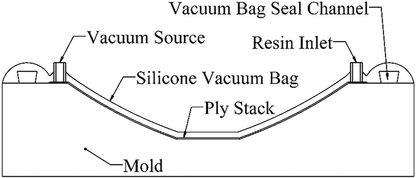
Example schematic of the vacuum infusion process.
There are two primary issues limiting the use of FGF tooling for VI. The surfaces of FGF tooling as printed often have too much surface roughness and porosity to ensure sufficient vacuum integrity for VI processing. However, this can be easily mitigated by machining and/or sanding the surface, then sealing it with a polymer-based coating.8,9 The FGF tooling also has lower durability than machined metal. The durability of FGF tooling, that is, how many parts can be made on a printed tool before it fails, depends on both the material properties of the surface and the surface energy of the part-tool interface. 8
Metallic molds are expected to endure thousands of manufacturing cycles, with little wear and an occasional resurfacing. The FGF tooling does not have the same longevity due to the significantly lower hardness of the thermoplastic matrix and the polymer-based surface sealant. Thus, FGF tooling is targeted at prototyping and short-production runs, where the cost for more durable tooling is unwarranted.
Several recent studies have investigated the durability of FGF tooling by comparing the original geometry of the tool surface with the same surface after composite layup. The first such study used an FGF tool, coated with an aromatic-hydrocarbon network-based surface sealant, to produce 10 parts by VI. 9 The mold surface after this series showed little damage, with an average surface deviation of only ±0.03 mm, whereas localized areas with higher deviation were attributed by the authors to measurement error.
A parallel study on autoclave processing made an FGF tool with high temperature matrices and no coating. 12 Sufficient vacuum was maintained by vacuum bagging the entire tool to an aluminum plate. One prepreg laminate was manufactured on the tool with an autoclave oven cure, with minimal surface deviation (±0.1 mm) after the process. A third study tested various surface treatments on FGF tooling for a series of hand (or “wet”) layup manufactured parts, with no vacuum consolidation during resin cure. 8 For uncoated tooling, some of the tooling material stuck to the parts as they were removed, resulting in a tool surface deviation of ±0.165 mm after five parts.
Various generic epoxy surface coatings were also tested, all of which failed by partial peel-off after only one to four parts. The authors concluded that the aromatic-hydrocarbon network-based coating used in the previous study 9 was far superior for this application. More recently, research has considered the use of more sophisticated surface coatings to harden the tool surface and improve wear. These include bonding a layer of either invar nickel-iron alloy or carbon fiber-bismaleimide prepreg composite to the surface15,16 or applying a coating of thermoset-ceramic composite.17,18 These options appear effective but are significantly more expensive and labor-intensive than applying liquid sealant.
Several application-based feasibility studies have also considered FGF tooling for specific desired parts. A mold for a valve cover was printed and subjected to six autoclave cycles, with the mold displaying noticeable but acceptable wear during the process. 19 In another study, a large autoclave mold was printed for the fabrication of a part upgrade for the Large Hadron Collider at CERN. 20 A two-sided compression mold for composites was also successfully manufactured. 5 These studies show that there is a desire to use this technology in composite molding, provided repeatable part quality can be maintained.
Because vacuum integrity is required for high-performance composite parts and completely enclosing the tool and a backplate 12 is difficult for large parts; understanding the long-term characteristics of the surface coating is a key part of increasing cycle-longevity. In addition to material choice for the tool and sealant, longevity is also geometry-dependent, that is, a flat part should result in the least surface area and thus the least adhesion forces to overcome when demolding the part. Any mold curvature would increase the surface area, and a tighter radius of that curvature or lower draft angles is assumed to have a more abrasive effect during part demolding on the coating.
The studies described earlier primarily involved mold patterns either flat or gentle curvature, that is, very large curvature radii. Actual industrial parts can have much more severe wear, as they often employ sharp corners and double curvature.
The studies cited earlier used either acrylonitrile butadiene styrene (ABS), polyphenylene sulfide (PPS), or polyether sulfone (PESU), as the pelletized thermoplastic feedstock. These materials were all reinforced by chopped carbon fiber, with fiber content ranging from 20% to 50% by weight. Carbon fiber has been shown to be a suitable material for this application in terms of its stiffness, thermal conductivity, and coefficient of thermal expansion.4,21 Fiberglass reinforced ABS (glass fiber ABS [GF-ABS]), on the other hand, exhibits lower stiffness 21 and lower thermal conductivity,6,22 but around 40% less cost than carbon fiber ABS for the same fiber content (20% reinforcement by weight).
Using GF-ABS would further reduce the cost of FGF-made tooling, but no work has yet been done to show the comparative durability of GF-based FGF tooling. The studies cited earlier indicate that tooling durability may be more related to the surface coating in VI applications than to the mechanics of the base material; thus, the cost-savings of using glass instead of carbon fiber may be warranted.
The purpose of this study is to investigate the durability of coated fiberglass ABS FGF tooling for VI by analyzing the deviations in the surface of the mold cavity over the course of multiple part infusions until tool failure. This adds upon the previous work in three ways. First, as explained earlier, this study will evaluate fiberglass reinforced ABS instead of the more expensive carbon fiber. Second, a “torture test” mold pattern will be designed that makes use of sharp corners, insufficient draft angles, and double curvature. Tool wear will also be accelerated by using a course plain weave of fiberglass fabric as the molded part. Third, the VI process will be repeated until mold failure, through more cycles than the previous studies attempted.
Materials and Methods
The research in this study did not involve human subjects and did not require IRB approval.
Test artifact design
To test the durability of this type of mold, it was first necessary to design a suitable test artifact and the printed mold to make it. Since the purpose of the test artifact was to explore the limits of the mold's durability, it incorporated the following common features, which tend to accelerate tool wear and/or introduce defects into the finished part.
Small or nonexistent draft angles, the angle being measured from the axis pointing in the direction of demolding.
Compound curvature, or areas of the artifact that are curved in multiple axes, that is, spherical or conical areas.
Small or nonexistent radii on edges.
In addition, to further accelerate tool wear, a fiberglass plain weave fabric was used in the infusion process, as fiberglass is more abrasive than other common reinforcement materials. A generic unsaturated polyester resin was used as the matrix.
An engineering drawing of the molded part is shown in Figure 3. Design guidelines for FGF
2
and three-axis milling were used to constrain the design of the test artifact mold to ensure its manufacturability. In particular, the following two rules were applied to the design:
All printed overhangs constrained to <35° from vertical. All machined surfaces accessible by a 1/4″ (6.35 mm) end mill with a 1″ (25.4 mm) cut length.

Mold fabrication
The print was prepared by exporting the SolidWorks model in STL format, with a coarse mesh to reduce print errors (deviation tolerance 0.51023585 mm, angle tolerance 30.00°). The STL file was then imported into ORNL Slicer (a 3D printing slicer developed for FGF by Oak Ridge National Laboratory) and aligned with the print bed so that the print direction is perpendicular to the machining direction, as seen in Figure 3. This orientation allows the machining to be done into the width of the print bead, which results in a smooth surface without defects or gaps. The print settings used for this mold are found in Table 1. Extrusion for infill was set at higher travel speed and lower extrusion rate and bead width, as compared with the perimeters, to decrease the print time and material used.
Print Settings
The print was completed on an AMBIT EXTRUDE from Hybrid Manufacturing Technologies, mounted in a HAAS TM-2P CNC milling machine. 1 The AMBIT XTRUDE has a 3-mm nozzle and is compatible with pellets up to 3 mm in length and build rates up to 9 kg per hour. The material used was Techmer 3-mm ABS pellets with 20% by weight short (∼300 nm) glass fiber, sold by Hybrid Manufacturing Technologies as AMBIT Feedstock 1202. 23 Before printing, the pellets were dried in a heated pellet dryer at 85°C for 3 h. To prevent moisture contamination over the long print duration, the feed material in the dryer was kept at 60°C throughout the printing process. A 1/8″ (3.2 mm) ABS sheet served as the print surface. The print took 255 min.
After printing, the mold was removed from the print bed and fixed to the mill table with toe clamps. Work offsets were set at the top center of the mold using a wireless probe. The mold was then machined according to the process chart shown in Table 2. The total cycle time for the machining processes was 407 min. This resulted in a total tool fabrication time of ∼11 h. The as-printed mold and the final machined mold can be seen in Figure 3.
Machining Operations and Parameters
Mold preparation
After the machining was finished, the tool was inspected for any defects. This included an initial laser scan to establish a baseline for comparison. The surface was scanned using a Hexagon Metrology ROMER Absolute 7530 SI seven-axis portable measuring arm equipped with a laser scanner. 24 The ROMER arm has a 3.0-m range and a published laser-scanning accuracy of 0.083 mm. An initial infusion was conducted to determine whether the mold could produce parts as machined with no surface sealant other than four coats of Partall® paste wax, and two coats of PVA sprayed mold release (spaced 15 min apart, followed by a 45-min dry time).
Vacuum testing of the resultant mold surface showed a leakage of 45 kPa (0.45 bar) in a minute, indicating insufficient vacuum integrity. Like in the studies described earlier, additional surface sealant was required to maintain sufficient vacuum for VI.
After the previous coatings of wax and mold release were removed, the mold was prepared with three coats of Chem Trend Chemlease® MPP 2737 mold primer (spaced 30 min apart) followed by four coats of Chem Trend Zyvax® 1050 mold sealer (spaced 30 min apart). Zyvax 1050 is an industrially proven hydrocarbon sealer for composites tooling, more aliphatic than that used successfully. 9 A reusable silicone bag was fabricated using Smooth-On EZ-Brush™ Vac Bag Silicone, using a trapezoidal channel along the tool edges to allow the bag to seal when subjected to vacuum pressure. Vacuum testing of the mold with this coating showed an indiscernible pressure change over 1 min, demonstrating acceptable vacuum integrity for VI.
VI processing
Before each infusion, two coats of Chem Trend Zyvax 1070W water-based mold release were applied (spaced 5 min apart). The ply stack was then placed on the treated mold, consisting of two layers of fiberglass plain weave fabric, with the second ply rotated 45°. A strip of release film and breather cloth was stretched diagonally across the ply stack to communicate vacuum from the outlet port across the mold cavity and to the seal channel. The mold was then covered with the silicone bag and vacuum tubing was inserted, as shown in Figure 4.
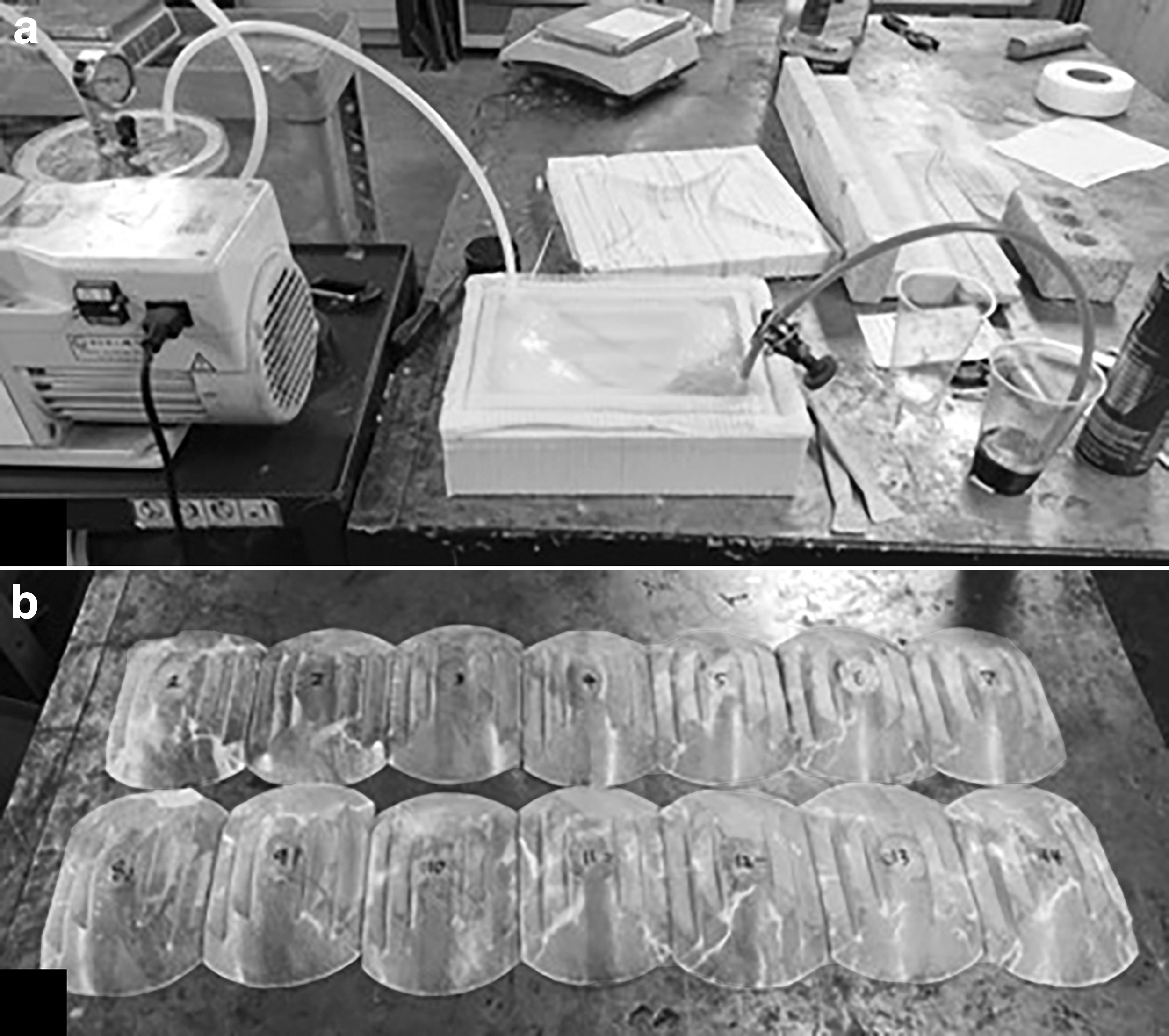
The polyester resin was mixed with 1.25% by weight of methyl ethyl ketone peroxide (MEKP) initiator and degassed for 1 min, and this was followed by infusion. Once resin flow was observed in the outlet, the resin inlet was clamped off, the vacuum pump was left on to evacuate any air trapped in the system, and the part was left to cure. After cure, the part was removed from the mold, as shown in Figure 4, and the mold was cleaned of residue using isopropyl alcohol.
The infusion process was repeated until tool failure. For the purposes of this study, failure was defined as any event that signals that the tool is no longer reliable for use in part production. As such, there are multiple theoretical failure modes, for example, surface deviation outside desired tolerances, insufficient surface quality, or extreme difficulty in releasing the part from the mold. Tolerances for surface profile geometry and requirements for surface finish are both subjective measures, as they depend on the manufacturer's desired level of quality. It was, thus, determined that parts would be infused until the demolding process became difficult enough that the part or mold was damaged during demolding.
Laser scanning metrology
After cleaning, the mold surface was scanned using the ROMER Absolute Arm 7530 SI described earlier. Each scan was conducted using multiple passes to obtain a polygonal mesh of the surface, first at fine resolution, then at extra fine. This was done using Innovmetric PolyWorks Inspector™, a commercial metrology software package. The scan data were then aligned to the CAD model of the mold using an iterative alignment process, which optimized the alignment of the data to minimize deviation from the CAD model. A color map of the deviation from the reference object surfaces was then generated, as shown in Figure 5.

This color map measures the deviation between each data point and the nearest point on the surface of the CAD model. Outlying scan artifact elements were then identified and removed. These outliers were classified as any elements reporting deviations on an order of magnitude larger than the largest other deviations. This was only necessary for a few of the scans, where there were 1–5 points with unusually large deviations. This process was repeated after each infusion.
The fabricated parts were not scanned due to their poor quality. This resulted from the many sharp edges in the part geometry. The relatively inflexible glass plain weave did not conform well to the sharp corners of the tool during infusion. The purpose of the design was to wear out the mold, not necessarily to produce high-quality parts, as testing this capability is outside of the scope of the current study.
Profilometry
After the infusions were completed, surface roughness measurements were taken on the mold in two locations to quantify the surface roughness before and after infusion processing. Some areas of the mold retained the same surface finish, as they were not exposed to the resin or reinforcement, such as the edges of the mold where the silicone vacuum bag contacted the surface, as seen in Figure 5. A Hommelwerke LV-150 profilometer was used to scan a 15 × 5 mm area and record the surface deviations with an accuracy of ±0.1 μm. This surface map was then passed through a Gaussian roughness filter, in accordance with ISO 25178,
25
and used to calculate the values of SA (arithmetic mean area roughness):
This is the two-dimensional equivalent of the RA value for surface roughness, which only uses a straight-line path of probing. L and B are the lengths of the sides of the rectangular area being probed, and η is the measured height relative to the reference plane at a given location in the area. Microscope images were captured of the measured surfaces for qualitative evaluation of surface roughness.
Results and Discussion
Failure mode
After 10 infusion cycles, it was observed that the part had become more difficult to demold. The surface of the mold was also observed to be rough and pitted, which could be felt with the hand. This degradation of the mold surface appeared to increase over the next four cycles, along with an increase in surface adhesion and thus increased difficulty of demolding. The tool failed after the 14th infusion, where the demolding difficulty increased to the point where the required force to demold damaged the part and the mold. It is possible that the mold could have been refinished by sanding and reapplying mold sealer once again.
Scanning results
The mold was scanned before applying surface treatments, after applying the primer and sealer, and following each infusion cycle. For each of these scans, Figure 6 shows the percentage of the mold's surface with significant (greater than ±0.1 mm) deviation from the original desired geometry and the root-mean-square (RMS) deviation of the total surface. The most significant change occurred after cleaning the mold and applying the sealer, which occurred between scans 1 and 2. This resulted from the sanding required to remove resin deposits and prepare the surface for sealing, as well as the thickness added by the primer and sealer.
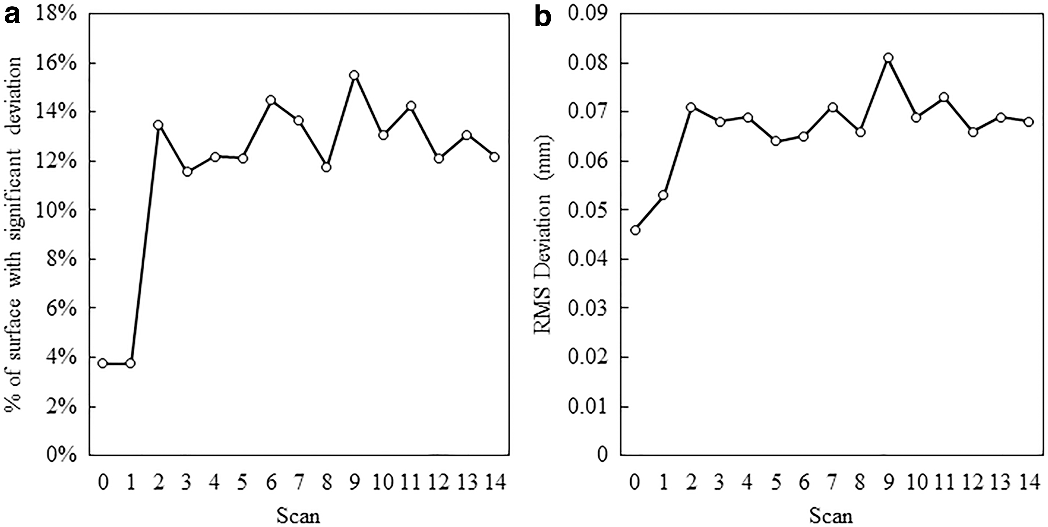
Both the percentage of affected surface area and the RMS deviation stayed relatively uniform, with no clear upward trend. From a macroscopic perspective, the tool stayed dimensionally accurate within ±0.5 mm over the course of the infusions, with no trends indicating a general increase in tool wear between cycles for the first 14 infusions. This low average surface effect over multiple part cycles with this glass-fiber modified plastic reaffirms the results for carbon fiber-based FGF tooling. 9
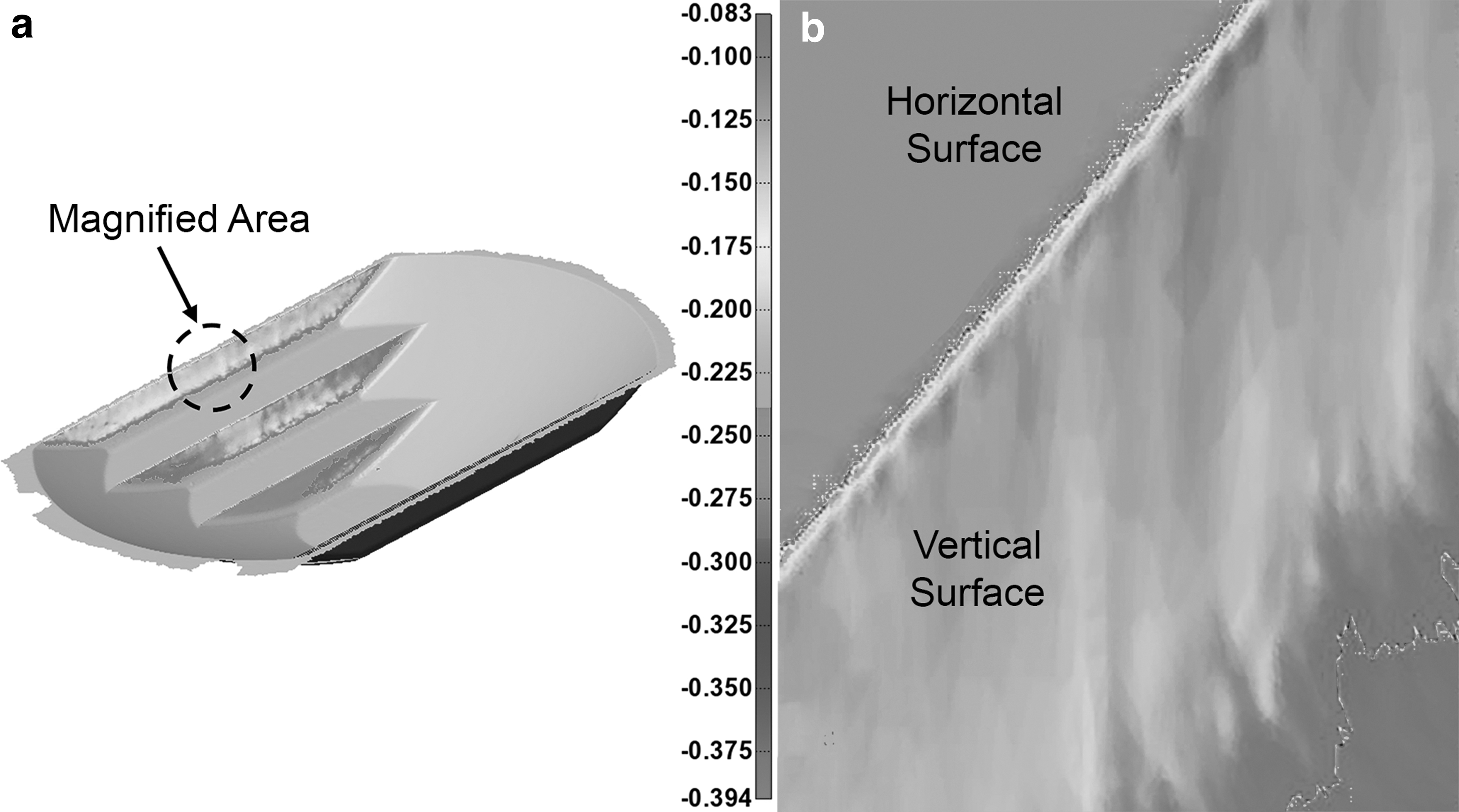
More beneficial observations can be made by looking specifically at the areas of highest deviation over the course of infusions. The areas of most significant wear are the inside faces and edges on the stepped portion of the test artifact (Fig. 7). The inside planar faces that were designed to have no draft angle caused significant abrasion of the surface, which resulted in increased deviation over the course of the infusions. These faces increased in deviation from ∼0.1 to 0.15 mm. In addition, the area of the greatest deviation, the sharp 90° corners, experienced even greater trends, increasing in deviation from ∼0.15 to 0.3 mm, as shown in the close-up image in Figure 7.
Profilometry results
Profilometry investigation to quantify the surface roughness of the mold before and after infusion processing showed a significant increase in surface roughness. After the 14 parts, an untouched section near the edge of the mold had a roughness SA value of 0.293 μm, whereas a visibly rougher section next to the cavity measured 2.27 μm. This means that over the 14 infusions, the tool surface increased in mean roughness by ∼775%. Surface maps of the measured profiles before and after infusion processing can be found in Figure 8.
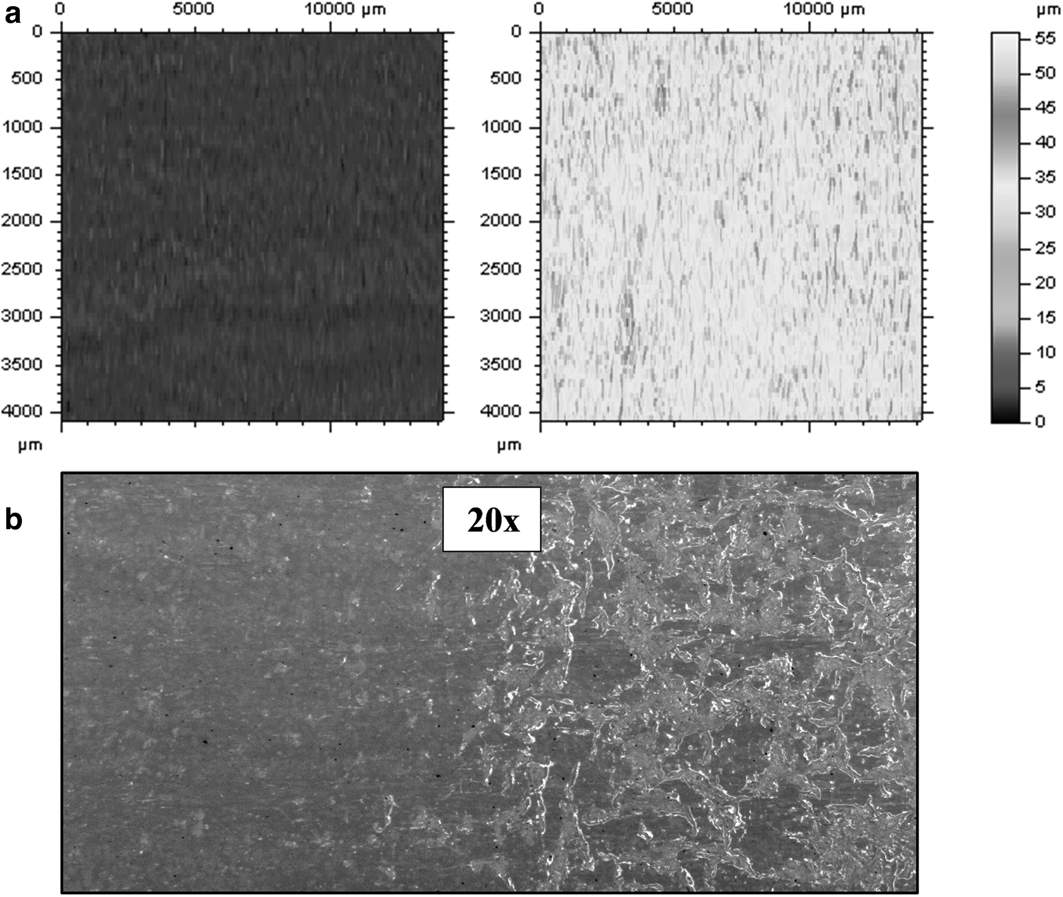
This increase in roughness is assumed to cause a related increase in adhesive bond strength over the course of infusion processing, which ultimately was the cause of tool failure. The increase in roughness is a result of microscopic deformations in the surface over time, such as the imprinting of the fiber tows on the surface and the removal of small pockets of material that are bonded together during the cure cycle. This results in a deformed and pitted surface, though the scale of this deformation is small enough to be measurable only through profilometry. Microscopic images of the mold surface before and after infusion processing can be found in Figure 8.
The increase in adhesion may also have resulted from the slow removal of the mold sealer, exposing the layers of mold primer and GF-ABS to the polyester resin. The chemical interaction between the polyester resin and the mold materials (sealer, primer, GF-ABS) is unclear and could be further studied.
Cost and lead time considerations
This study was part of a larger effort 26 that also included an expert survey of customer expectations for composite molds, expected costs and lead times for different mold options, and a cost analysis of the test mold described here. To print and machine the FGF mold from GF-ABS, the analysis concluded that it would cost ∼$700 (material cost and combined machine time for printing and machining) and take about 11 h. For comparison, the online quoting service for Xometry, a manufacturing-on-demand marketplace, 27 prices the same test mold at $1,000 for machined aluminum or $1,200 for machined ABS, with a lead time of 2 weeks.
The expert survey in Northrup 26 showed that for actual industrial molds and dedicated suppliers, the lead time could often be closer to 4–12 weeks. It seems that the competitiveness of FGF molds versus conventionally machined molds is highly dependent on the complexity and size of the design and the promised lead time, but there certainly may be situations where such molds are a desirable option.
Conclusions
A 20% GF-ABS mold for VI of composites was fabricated and subjected to 14 molding cycles before failure. Failure was caused by an increase in adhesion between the GF-ABS mold surface and the fiberglass/polyester composite laminate during the cure cycle. Surface scanning metrology showed that the mold surface remained dimensionally accurate over the course of infusion processing, with no discernible general trends in macroscopic tool wear. Wear patterns were identified on the inside planar faces with no draft angle, as well as the sharp corners designed to wear quickly over time. Profilometry measurements showed a >7 × increase in mean areal surface roughness (SA) over the course of infusion processing. This is linked to the visible degradation of the surface, which, in turn, is related to the increase in adhesive bond strength.
These results indicate that this combination of method and materials can be used to produce short runs or prototyping of composite parts. One major limitation of a study like this is the number of variables that can influence the outcome. As such, these results are only applicable for this specific combination of fabrication method, mold material, composite matrix and reinforcement, part geometry, and mold sealer. Since this test was done under an extreme case for part design as well as abrasive matrix/reinforcement materials, 14 parts is a reasonable worst-case minimum tool life that can be expected.
Much higher run quantities are likely for typical applications with less abrasive materials and more production-oriented design. Since failure was due to surface finish and not any appreciable wear or change in tool geometry, the tool could also be resurfaced to extend its longevity without the cost of additional printing costs.
Footnotes
Authors' Contributions
N.N.: Conceptualization, formal analysis, writing—original draft, and visualization. J.M.W.: Methodology, resources, writing—review and editing, and supervision. A.R.G.: Methodology, resources, and writing—review and editing.
Author Disclosure Statement
No competing financial interests exist.
Funding Information
This work has been funded by the Manufacturing Engineering Department of Brigham Young University (Provo, UT).