
Abstract
The ongoing crisis caused by the COVID-19 pandemic produced major reshuffles on the world map, bringing imbalance, uncertainty, and accumulated stress. Due to supply chain disruptions, the need for innovation has emerged both as a priority and a necessity and three-dimensional printing (3DP) proved to be a primary, smart, effective, and innovative additive manufacturing (AM) method. AM refers to the direct fabrication of complex geometries, using a computer-aided design (CAD) model or a three-dimensional scanner output. This article presents a literature review of AM technologies, chronologically sorted, and proposes a multilevel classification model. The suggested research approach appears a triangular methodology that encompasses the current ISO/ASTM 52900:2021 report. The first objective of this article is to form two double-level classification models of AM processes, depending on the technology and material factors. The second objective is to clarify in which of the proposed categories each AM process is included; and the third one is to investigate if the proposed taxonomy is related to the time spot, in which AM processes were invented. The contribution of this article lies in determining the factors that are crucial for the growth of AM ecosystem. The novelty of the proposed classification lies in the definition of an optimal option for each industrial application based on the different AM processes, the variety of materials, and the evolution of technology over the years. In this way, investing in AM is more systematic and less risky.
Introduction
In an era of rapid business growth and innovation, global development dynamics are likely to lead to social emergencies and geopolitical tensions, facilitating appropriate conditions to cause a global socioeconomic shock on various levels. The COVID-19 pandemic has caused major reshuffles on the world map, bringing imbalance, uncertainty, and accumulated stress. People were urged to stay at home, minimizing their contacts, and enterprises were forced to reduce or stop their activities, looking for ways to survive through new alternative business models.
Due to the market uncertainty caused by the COVID-19 pandemic, the need for innovation has arisen both as a priority and a necessity. The adoption of digital technologies in business operations and production management promoted innovative ways for recovery and enabled new strategies, practices, and processes. Innovation strategies that have been adopted include business collaboration with appropriate partners and the development of innovative products through their digital transformation. The constantly increasing use of digital technologies offered a significant and positive result in business dynamic capacities and provided a beneficial impact on their sustainability amidst the era of stress and instability. 1
Additive manufacturing (AM) is progressively developing and enhancing fabrication processes, causing a real revolution in the fields of product design, process planning, and supply chain management. Three-dimensional printing (3DP) proved to be an intelligent and effective AM technology, as it could fabricate locally complex models using digital designs and decreasing lead times, as well as remotely, shortening the production process and introducing the digital supply chain. 2
3DP is an AM method for fabricating a wide range of complicated structures using digital model data.3,4 The object is divided into several layers, using slicing software, and then these layers are successively printed out and bonded together, through a material deposition process with options set by the operator. Nowadays, all AM systems are based on the same operation approach of layers' configuration, differing in the built process and material used. The basic principle of 3DP is based on a model that is first created, using a computer-aided design (CAD) software or a three-dimensional (3D) scanner, and then is directly built, without having to plan the production process.
3DP technology refers to four distinct market sectors, which present different stages of maturation. Since the 1980s, when 3DP knowledge was still in its infancy, industries began to apply this technology to rapid prototype models before the final decision of mass production. A little bit later, but rapidly, 3DP technology was applied for manufacturing casts, molds, and other supporting tools for the production process. Since the 2000s, 3DP is aimed to produce final objects, directly exported to the market, setting up the concept of Direct Digital Manufacturing (DDM). DDM is “the process of going directly from an electronic digital representation of a part to the final product through additive manufacturing,” which gradually forms a new market, concerning personal fabrication and customization. 5 Other areas where 3DP technology is being researched and applied concern the construction and biomedical sector, sports and robotics, agriculture, and earth science, as well as the aerospace, the automotive, the and toy industries, and the food sectors. 6
3DP seems to gain the interest of various companies from different industries, like aerospace, automotive, arts, and construction. The benefits are numerous and the future for further development is promising. The design freedom, the mass customization, and the ability to print complex geometries with minimal waste production and energy consumption make 3DP an attractive and innovative technology.3,7 Moreover, building complexity and variety are free, which means that 3DP systems can bring out various complicated shapes with no additional time, skill, or cost, just using a different digital blueprint and a new feedstock. 3DP provides new capabilities for organizing, improving, and effectively planning the manufacturing processes.8,9 Product batches difficult to be stored in a physical or online store due to high costs can be easily produced on demand, minimizing the lead time and the stock inventory.10,11 In addition, this technology allows the production of personalized goods in small batches at a low cost. 12 The demand for custom-made products releases great chances and new challenges, both for new material design and production processes.
3DP technology is estimated to be a rapid, cost-effective solution for enterprises, as well as for individual customers.13,14 Although the benefits of 3DP technologies are various, there are also some drawbacks, leading to printing errors and degraded product quality. The void formation, the anisotropic behavior, the limitation of CAD, the layer-by-layer appearance, the gap between design and printing process, and finally the mechanical performance are the key challenges of 3DP. 3
3DP includes a wide range of AM technologies, which are also described by different terminology. The main AM methods have been identified and established by International Organization for Standardization and the American Society for Testing and Materials (ISO/ASTM 52900:2021) and include seven defined process categories, which contain Binder Jetting (BJT), Directed Energy Deposition (DED), Material Extrusion (MEX)—widely known as Fused Deposition Modeling/Fused Filament Fabrication (FDM/FFF), Material Jetting (MJT), Powder Bed Fusion (PBF), Sheet Lamination (SHL), and Vat Photopolymerization (VPP)—commonly known as Stereolithography (SLA). 15
AM processes, as defined by ISO/ASTM report, can be grouped into single-step and multistep processes. Single-step processes perform the ability to build the basic geometry, achieving simultaneously the basic material properties of the printed project. Multistep processes are considered the AM technologies that typically build the basic geometry in an initial stage. A postprocessing procedure is required to provide the printed part with the fundamental quality performance. The removal of the additional support structure, as well as washing, powdering-off, and other cleaning-up procedures, are not included in postprocessing techniques (PPTs).
The quality performance of the final object is defined by the surface and material properties, which can be evaluated by quantitative and qualitative factors. The choice of AM technology should be based on a case-by-case study to adequately address the most critical requirements of the printed parts. Strong factors that affect selecting the appropriate AM technology for specific applications are—mainly—cost and accessibility, dimensional accuracy, sterilization possibility, fabrication speed, resolution, build volume capability, durability, mechanical performance, and basic requirements for surface finish and other PPTs. 1
Some researchers have already proposed different taxonomies either to organize their outputs using classification models or to facilitate the understanding of their results. The most common criterion that researchers choose to categorize AM technologies is the material used. However, the state and the type of raw material are not effective classification inputs, as they do not significantly affect the evolution of AM technologies. The article of Kruth proposed a two-dimensional (2D) classification model, according to the state of materials and the shape building techniques. Concerning the criterion of materials, Kruth organized 3DP technologies into three groups; powder, liquid, and solid processes, depending on the initial material that each technology uses. 16
Later, Kruth et al enriched this classification model, suggesting a supplementary material category, which referred to the gas, 17 which did not gain the same interest from the scientific community, as his first model did. Specifically, Chua et al pointed out the same material criteria to categorize AM processes as Kruth did. The difference lies in the connection of the material with the fabrication method. In the work of Chua et al, solid-based technologies describe either cutting and joining techniques or melting and solidifying methods, liquid-based technologies refer to curing processes, and powder-based technologies are related to fusion techniques. 18
Other studies encompass more categories in AM classification model based on the initial material. Prakash et al and Bhuvanesh Kumar et al differentiate the materials' categories and include in their taxonomies the liquid, the paste, the powder, and the solid sheet categories.19,20 The article of Prakash et al deals also with another classification model, using as a criterion the type of the material and suggesting the categories of polymers, metals, ceramics, and composites. 19
Kruth in his study had also categorized AM technologies according to the fabrication method, suggesting two groups, which include the direct 3D method and the 2D layer technique. 16 Pham and Gault deal also with a 2D classification model, related to the building method of layers and the raw material that is applied. 21 Gibson et al modify the classification model of Pham and Gault and propose five categories for AM technologies based on the fabrication method, which include point, pointwise, line, layer, and volume processing systems.10,21 Finally, ISO/ASTM 52900 classifies AM technologies into single-step or multistep processes, depending on the variety of operations that individual parts must perform to be fabricated. However, it has not been specified to which category each ΑΜ technology belongs. 15
According to the literature, there is limited research on the classification of AM technologies and additionally, there is no reference to the correlation between the different types of AM technologies and their evolution over time. The existing taxonomies are limited in covering the criteria of the material and the fabrication method. To provide a holistic view, this article aims to propose new systematic classification criteria, based on the two main categories of technology and material, focusing on the relationship with the timeline.
For the technology criterion, two subcriteria are used: the mechanical parts of different 3D printers' technologies are introduced, and the grouping of ISO/ASTM 52900 report is utilized. For the material criterion, two subcriteria are also used: the feedstock state and the material type, by the classifications proposed in the literature.16,18–20 This study examines if the deposition mechanism, the postprocess requirements, the feedstock format, and the material type are influenced and in which way by the time factor. This article aims to determine which key factors influence the evolution and development of 3DP technologies.
This article's structure is organized as follows: in Research Design section, the methodology framework is presented; A Historical Snapshot of AM Processes section analyzes separately each ΑΜ technology, as defined by ISO/ASTM 52900, in such an order depending on the year of its invention; Double-Level Classification Models section introduces the new classification model and highlights how different AM technologies are affected or not by the time-sensitive factor; Discussion section presents the findings and the limitations of the work; and Conclusions section summarizes the results, introducing the critical thesis of the authors and proposing directions for further research.
Research Design
In this study, a combination of a systematic and narrative literature review was conducted, as a two-stage process referred to the material collection and knowledge classification, identifying content patterns and description themes. During the review designing phase, the purpose and the hypothesis of the current research led us to collect, analyze, and synthesize the selected material in a systematic, transparent, and reproducible way, creating the basis for building a new conceptual classification model. 22 We developed a specific search strategy, according to which we took clear decisions about the databases, keywords, and inclusion criteria for selecting previous articles. Figure 1 represents the research approach for the proposed classification model of standard AM technologies, as defined by ISO/ASTM 52900:2021. 15
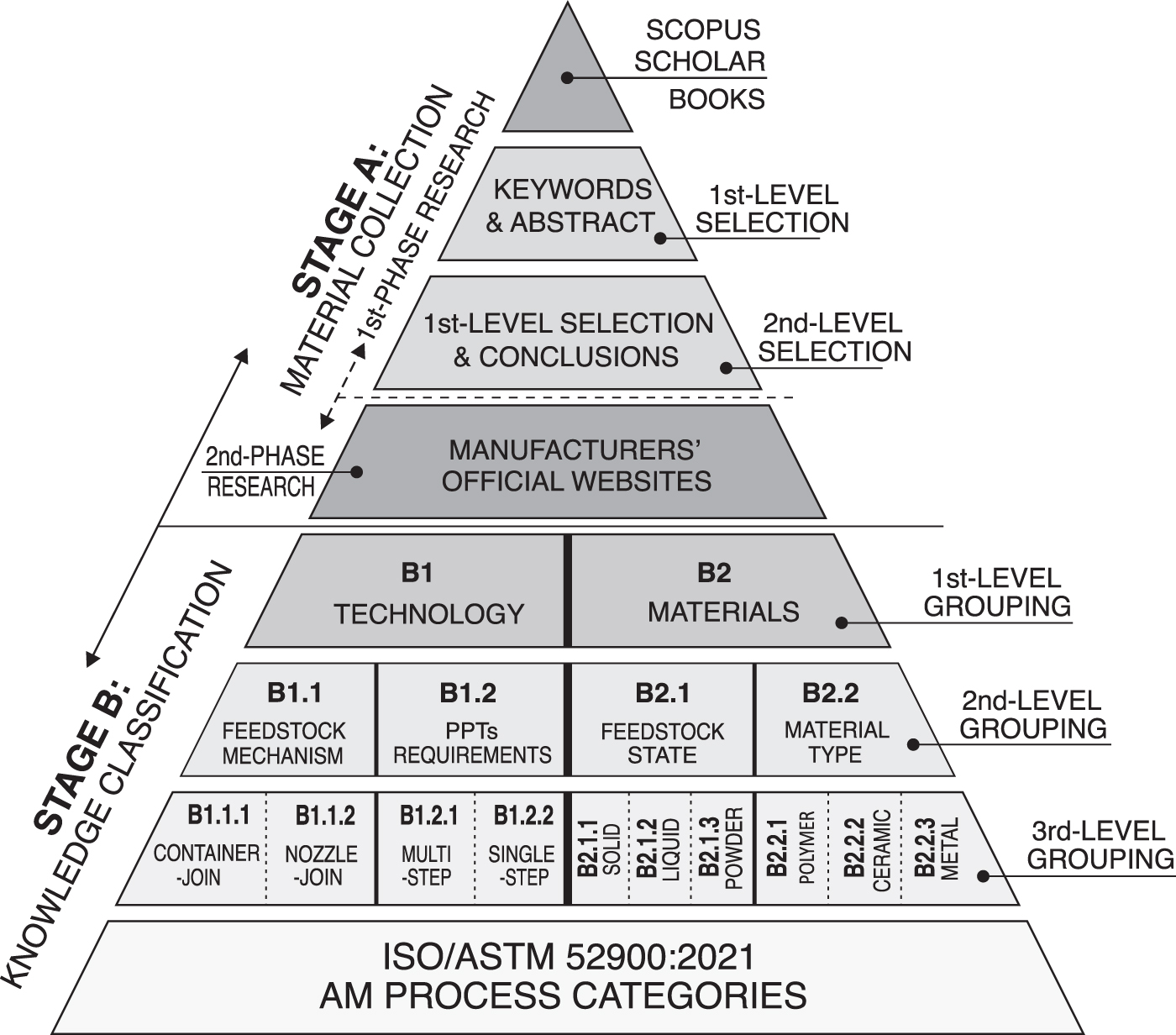
The methodology approach of the proposed classification model.
In the first stage, an initial scan of published literature was carried out related to AM technologies and materials. This involved comprehensive research in published books, as well as Google Scholar and Scopus databases, using the keywords “3D printing” and “additive manufacturing,” combined with “AM technologies,” “AM materials,” and “AM applications.” In this stage, interdisciplinary articles concerning AM technologies were selected and studied, including both applied research and theoretical reviews. Delimiting research material, it is important to define clear boundaries to what is included and evaluated in material resources and what is not. The objective of this literature review is focused on the printing process and the material selection of AM methods, which means that scientific articles referring to operations and supply chain management of AM technologies are excluded from any content evaluation.
A first-level selection of articles arisen was conducted by reading the abstracts and assessing whether the content is relevant to our research subject. The interest criteria were focused on the printing process, the terminology, and the materials commonly used, in combination with the factors that affect the printing result, the benefits, and the challenges of each method. In case the article was relative to our research topic, we proceeded to read the conclusions to make a final selection of the selected articles (second-level selection). More recent articles have been mainly preferred, without extruding the selection of older articles with high scientific interest.
Additional second-phase research was performed using the Google platform and searching for the enterprises' official websites to introduce and enrich information about the applications and the basic companies, which integrate AM technologies in their production processes (Fig. 1). Finally, 116 scientific and professional resources—including articles and official websites—were selected and evaluated to be studied in-depth and included in the bibliography of this article.
The second stage of the research approach refers to material analysis and grouping of the diverse material to further categorize the AM technologies. The base of the suggested AM classification lies in the standard categories of ISO/ASTM 52900:2021. 15 Initially, the first-level grouping refers to the criteria of technology (Fig. 1, B1) and materials (Fig. 1, B2).
Concerning the technology, two groups are defined, according to the way the feedstock is deposited into the print bed (Fig. 1, B1.1) and the further requirements for PPTs (Fig. 1, B1.2). Concerning the materials, the AM methods are grouped into the categories of feedstock state (Fig. 1, B2.1) and material type (Fig. 1, B2.2). Following this methodology approach, 10 subcategories are structured, and finally, ISO/ASTM standard-defined technologies were included in the proposed subcategories, according to their specific characteristics.
Finally, to ensure the quality of the review conducted, three primary objectives had to be achieved: adopting an appropriate strategy regarding the selection of articles and data collection, the replicability of the research, and the clarification of its contribution and impact on the general public. 22
A Historical Snapshot of AM Processes
The invention of ΑΜ technologies came up in the 1980s and is still evolving dynamically today. The first 3DP concept is granted to Hideo Kodama for his development of a rapid prototyping technique, presenting a layer-by-layer approach for manufacturing, but did not catch up to file the patent requirements within the time limit. 23
The official beginning of 3DP technologies dates to 1986 when Chuck Hull made history by inventing SLA as the first patent of AM technologies. 24 In 1988, Card Deckard, Professor at the University of Texas, filed a new patent for Selective Laser Sintering (SLS) technology, based on PBF methods. A year later, in 1989, Scott Crump, co-founder of Stratasys, filed a patent for another key technique of 3DP, FDM, which describes the MEX methods. 25 In 1991, Helisys, Inc., was the first company to introduce SHL technology to the market. BJT technology was initially developed by Ely Sachs and Mike Cima at MIT in 1993. 26 Due to the quality results, the American enterprise Z Corporation received it 2 years later, taking up all rights to this technology. DED was developed in 1995 by Sandia National Laboratories, under the term Laser Engineered Net Shaping (LENS), and then was commercialized by Optomec Design Company. 27 Finally, the MJT technology was developed by Objet Geometries Ltd. in 1999 and later was acquired by Stratasys in 2012. 28
Thereupon, a systematic review of the standard AM processes is presented, chronologically sorted, according to the time spot that each one was invented. This section is divided into seven subsections, analyzing each AM process separately. The structure of each presentation is organized as follows: Αt the beginning, a brief history, and the mechanical structure of a typical system are presented to describe and explain the operational principle of each technology. Then, possible classification and different terminology of similar techniques are mentioned, as well as the materials usually applied in each AM process. In addition, the factors that affect the printing quality, the benefits, and the limitations of each technology are listed, while at the end of each subsection, the leading manufacturers and the most common applications of each AM method are discussed. Table 1 provides a comprehensive overview of standard AM processes, as defined by the following subsections.
A Comprehensive Overview of Standard Additive Manufacturing Processes, Based on Our Research Approach
2PP, Two-Photon Polymerization; 3DCP, 3D Concrete Printing; 3DP, three-dimensional printing; AM, additive manufacturing; BJT, Binder Jetting; CAM-LEM, Computer-Aided Manufacturing of Laminated Engineering Materials; CBAM, Composite Based Additive Manufacturing; CC, Contour Crafting; CJP, Color Jet Printing; cDLP, Continuous Digital Light Processing; CLIP, Continuous Liquid Interface Production; DED, Directed Energy Deposition; DIW, Direct Inkjet Writing; DLF, Directed Light Fabrication; DLP, Digital Light Processing; DLS, Digital Light Synthesis; DMD, Direct Metal Deposition; DMLS, Direct Metal Laser Sintering; EBAM, Electron Beam Additive Manufacturing; EBM, Electron Beam Melting; EFF, Extrusion Free-Forming of ceramics; EHDP, ElectroHydroDynamic Printing; FDC, Fused Deposition of Ceramics; FDM, Fused Deposition Modeling; FDMM, Fused Deposition of Multi Materials; FFF, Fused Filament Fabrication; FFM, Fused Filament Method; LBM, Laser Beam Melting; LCD, Light Crystal Display; LDM, Low-temperature Deposition Manufacturing; LDW, Laser Deposition Welding; LENS, Laser Engineered Net Shaping; LFF, Laser Freeform Fabrication; LMBD, Laser-Based Metal Deposition; LMD, Laser Metal Deposition; LMF, Laser Metal Fusion; LOM, Laminated Object Manufacturing; LS, Laser Sintering; LSF, Laser Solid Forming; MEX, Material Extrusion; MJF, Multi Jet Fusion; MJP, Multi-Jet-Printing; MJS, multiphase jet solidification; MJT, Material Jetting; NPJ, NanoParticle Jetting; NPJ, NanoParticle Jetting; PμSLA, projection micro stereolithography; PBF, Powder Bed Fusion; PEM, Precise Extrusion Manufacturing; PJP, Plastic Jet Printing; PPTs, postprocessing techniques; PSL, Plastic Sheet Lamination; RPBOD, Rapid Prototyping robotic dispensing; SDL, Selective Deposition Lamination; SHL, Sheet Lamination; SHS, Selective Heat Sintering; SLA, Stereolithography; SLCOM, Selective Lamination Composite Object Manufacturing; SLG, Selective Laser Gelation; SLM, Selective Laser Melting; SLS, Selective Laser Sintering; UAM, Ultrasonic Additive Manufacturing; VPP, Vat Photopolymerization; WAAM, Wire and Arc Additive Manufacturing.
Vat photopolymerization
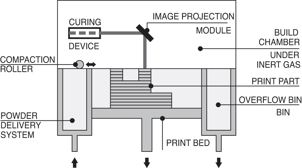
As mentioned above, the VPP method was first developed and established by Charles Hull in 1986 with a process commonly known as SLA. SLA method was commercialized by 3D Systems, Inc., and the obtained patents expired in 2014–2016. 29 A typical VPP technology system includes the curing device, the image projection module, the fabrication platform, the vat of photocurable resin, and a blade mechanism (Fig. 2). The VPP technology uses a light source with certain wavelengths to scan and then form and solidify successive layers within a vat of liquid photo-curable material. The light beam is reflected on galvanometric mirrors focusing on the surface of the liquid and gradually forms each separate layer moving along the X and Y axes.30,31

Schematic representation of VPP technology system and process. VPP, Vat Photopolymerization.
The basic principle behind this process is a photochemical reaction to be conducted on a layer of monomer resin or solution and to chemically activate and instantly convert a reactive monomer to polymer structure after radiation. When the layer is complete, the fabrication platform sinks into the vat to the thickness of a layer and then an additional layer of resin is spread across by a blade mechanism. The remaining material that has not been photocured and therefore was not hardened is removed from the vat after the printing process completion.32,33 A postprocess treatment of heating or photocuring may be implemented to improve strength and achieve the desired mechanical performance.
In the case of SLA, the applied light refers to a point-source laser beam, which cures the photosensitive resin. Other types of radiation used in VPP methods are gamma rays, X-rays, electron beam, LED, and ultraviolet (UV) light. 10 Digital light processing (DLP) is a technique, where each layer is solidified by the projection of a mask pattern; light crystal display (LCD) uses an affordable LCD screen producing less distortion and higher resolution; continuous liquid interface production (CLIP) has a faster printing speed; volumetric 3DP fabricates the part directly in 3D within a rotating vat and without forming successive layers; 29 and digital light synthesis (DLS) uses a LED light source with lower power and intensity and therefore could not work effectively with a wide range of materials.
Other VPP methods are two-photon polymerization (2PP), projection micro-stereolithography (PμSLA), electrohydrodynamic printing (EHDP), and noncontact micro- and nano-printing. 3 SLA has also been extended to ceramic materials and in this process, a photocuring binder with ceramic fillers is used. If the liquid binder is filled with a high rate of ceramic fillers, the process is called direct stereolithography (CSL), while if the binder is a nonfilled photocuring liquid, this method is called indirect SLA, and the object produced can be used as a mold for ceramic casting. 34
In VPP methods, liquid resins of photopolymers, ceramics, composites, and hydrogels can be cured when activated by a light source.35,36 VPP materials can be classified into engineering, dental, industrial, and general-purpose resins.37–39 It is also important to highlight that VPP technology is a nonmetal AM method, mainly used for rapid prototyping. The quality result of a part, printed using the VPP technology, highly depends on the layer thickness, which is successively affected by the energy intensity, as well as the exposure of the photocurable material to the light source.
VPP technology provides a wide range of benefits and advantages. Photopolymer-based systems can offer flexibility, dimensional accuracy, thin layers, and high printing resolution, delivering fine precision and excellent surface finish quality. Moreover, complex geometries are capable to be fabricated, while improved temperature resistance, strength, ductility, and high reliability are the main advantages of VPP methods.7,10 In addition, polymer-delivered ceramics do not require to be post-treated, which thereby shortens the manufacturing time, while porosity control and high flexural strength can be achieved using ceramics and composites as a feedstock.
However, in VPP methods, a limited variety of available materials can be applied, and these technologies are highly expensive, due to the cost of their feedstock. Although new materials are constantly being developed, the thermomechanical properties of photopolymers require to be further optimized. Specifically, SLA technology works with photopolymers, which are not stable over time and do not have well-defined mechanical properties. In addition, for photopolymer-based systems, a support structure is required due to the liquid form of the resin. Low fabrication speed is another drawback of the process and in case of a material alternation needed, the fabrication time is significantly increased.
Concerning polylactic acid (PLA) resins, it is a challenge to maintain the material's viscosity, which can be achieved through the temperature increase during the process, as well as the use of plasticizers, avoiding any thermal degradation. 3 Another challenge for SLA technologies is to develop eco-friendly parts, combining simultaneously good physical properties. Although SLA offers a smooth surface finish, it has the drawback of brittleness if exposed to moisture and sunlight. 29 SLA is susceptible to UV and rapid thermal degradation over time and thus a UV protective coating as a post-treatment technique is highly recommended.
Concerning the applications of VPP methods, SLA technology is widely used in the following industries: Aerospace and Defense, Automotive, Jewelry, Motorsports, Semiconductor, and Turbomachinery. 40 Other SLA applications refer to Engineering, Medical and Dental sector, and Audio and Entertainment, 37 while DLP and Continuous DLP technologies find further application in Architecture and Design, Molding, Footwear, Consumer products, Education and Research, Hearing aid, and Biofabrication.38,41–45 The leading manufacturers and suppliers of VPP AM systems are 3D Systems, Inc., FormLabs, DWS Systems, PrismLab, B9 Creations, Prodways Tech, Carima Co. Ltd., Carbon, and EnvisionTEC.
Powder bed fusion
In 1988, Carl Deckard from the University of Texas got the patent of SLS technology, a 3DP technique, which is included in PBF methods. 23 In 2014, the core patents of the SLS technology expired. 46 A typical PBF system consists of a curing device, an image projection module, a fabrication platform (i.e., print bed), a powder delivery system, and a compaction roller, which is a mechanical system for adding and smoothing the powder layers (Fig. 3). PBF techniques use a high-density heat source to melt and fuse selectively solid grains of powder spread in thin layers.
Schematic representation of PBF technology system and process. PBF, Powder Bed Fusion.
Specifically, a certain amount of powdered material is spread on the built-up plate, using a mechanical roller that moves along the X-axis. This roller moves backward and forward successively to assure good powder compaction for each layer. The powdered material is locally preheated to a temperature that is just below the powder's melting point to prevent the warping of the part during the building process. A focused energy beam is moved using galvanometers and is directed onto the print bed, scans across the powdered surface, and fuses selectively the layered material. After a layer's completion, the build platform is lowered to one layer thickness and subsequent layers of powder are rolled on top of the previous and bonded together until the complete part is built. A cool-down period is typically required to let the part gradually adapt to ambient temperature, avoiding any part deformation or material degradation due to the presence of oxygen. The unfused powder can act as support material and can be reused after printing. 30 The final print part is embedded in a block of powder and when the printing process is complete, the excess powder is removed through PPTs to knock powder off.
Several postprocessing operations are required in PBF methods to improve the total quality of the printed parts, including the mechanical properties, dimensional accuracy, and surface quality. These procedures can be classified into mechanical and heat treatment (HT) processes. The first one is mandatory and usually includes sandblasting and shot peening to improve the surface finish attained in the built-up plate, as well as machining and grinding to ensure interchangeability during the assembly process. 47 The second one is stress-relieving HT processes, which are highly recommended by the manufacturers of PBF systems. HT methods must be submitted before removing the part from the built-up plate to improve the stability, due to an increase in the material hardness and additionally to avoid any undesirable geometrical distortion of the built part.
PBF methods can be classified into four categories depending on the energy source used for fusion. Therefore, there are thermally fusion systems, like Selective Heat Sintering (SHS), which apply one or more thermal sources, laser fusion systems, like SLS, electron beam fusion systems, like Electron Beam Melting (EBM), and systems that perform fusion with agent and energy, like Multi Jet Fusion (MJF). For laser-based technologies, it is required to work in a protective environment inside the build chamber. When working with steel powder, nitrogen is commonly used, while for processing titanium and cobalt-chromium, argon is the best option. 7
PBF methods are described by a wide range of terminology, including Laser Sintering (LS), Selective Laser Melting (SLM), developed by Dr. M. Fockele, 48 Laser Beam Melting (LBM), Laser Metal Fusion (LMF), Selective Laser Gelation (SLG), Direct Metal Laser Sintering (DMLS), laserCUSING, and High-Speed Sintering.5,35,49,50 Although the basic operational principle for all methods is the same, little differences are observed in each distinct technology. SLS through laser scanning is based on melting partially the powder material, while in SLM, the powders are fully melted and fused, leading to improved mechanical properties. The difference between SLM and EBM concerns the energy source, as the first one uses a laser beam, while the second an electron beam.
PBF built materials range from thermosetting and thermoplastic polymers to concrete, metals and their alloys, ceramics, and their composites. 51 It is also possible to fabricate objects using a powdered mix of plastic and metal materials. There are some PBF technologies, which can be used for a variety of raw materials, while others are limited by specific feedstocks. Specifically, SLS technology is compatible with a wide range of polymers, while the SLM method can only be used for certain metals. Metal materials, like stainless and tool steels, aluminum alloys, titanium, and nickel-based alloys, as well as polycarbonates (PC), nylon, wax, ceramics, elastomeric, and metal-polymer powders, can be manufactured using PBF-based AM processes.46,52
The main parameters that have a major influence on PBF printing results are the print bed temperature, the beam power, the speed of scanning, the scan size, the scan spacing, as well as the beam size, the beamline focus, and the slice thickness. 47 Moreover, geometrical and dimensional accuracy and reliability can be affected by the orientation of the compaction roller, as well as the movement direction. Powder size distribution and packing determine the part's density, and therefore, they are crucial factors for the method's efficacy. The applied energy volume, the level of contaminants, and the feedstock quality are factors that can affect the porosity. Low amounts of energy develop irregular-shaped voids, while excessive energy power generates spherical pores. Heat penetration of the laser beam into each layer is an important factor for not only controlling the sintering process but also limiting anisotropic behavior. Other laser-related factors, which influence the printing quality of PBF methods, are pulse duration and frequency, powder feeder temperature, and temperature uniformity. 10
PBF methods can offer significant economic advantages by producing very complex structures at a lower cost with less powder waste. 53 The main advantages of PBF methods are the quality of printed objects and the wide variety of materials available for use. The fine resolution, advanced geometries, high printing quality, and the ability to self-hold the support structure are also some of the main benefits of PBF methods. SLM technology permits the production of high-complex, fully functional, metallic parts,47,54 while the polymers and especially the thermoplastics used in SLS methods are eco-friendly materials, which can be recycled and reused.
PBF technologies can manufacture components with good mechanical properties and stiffness, increased yield and ultimate strengths, and complex shapes with high accuracy. In addition, freedom of design, manufacturing of lightweight structures, resistance in chemicals, and multiple part consolidation, which can eliminate the assembly phase, are additional advantages of metal AM powder-based methods. If the polymer feedstock is reinforced with glass fibers or aluminum, it also performs high temperature resistance and good behavior in high humidity conditions.
According to Rafiee et al, PBF technology is inherently a mono-material method. 53 During the PBF manufacturing process, residual stresses on 3D printed parts are produced due to thermal expansion, and therefore negative effects may be observed in dimensional accuracy. In addition to other factors that cause dimensional accuracy errors, such as laser spot position, deformation may also occur due to thermal stresses. The anisotropy of the material's microstructure and the surface roughness may cause earlier failure under fatigue loading due to stress concentrations. Although sintering and melting methods can print dense parts, high porosity, combined with low build speed, is the main drawback, which makes the process more suitable for small parts' fabrication. To summarize, although PBF methods are more time-consuming compared to other AM methods, they are high in resolution, 55 which thereby requires a higher amount of energy, longer processing time, and higher cost for 3DP.
PBF methods, due to their printing quality, are broadly used in advanced applications, such as Aviation, Space, Electronics, Automation and Gripping Systems, Tooling, Turbomachinery, Sports, Lifestyle and Consumer goods, 56 Automotive, Art and Design, Shoe Industry, 57 Energy, Heavy industry, Health care, 49 and Military. 58 The leading manufacturers and suppliers of PBF AM systems are EOS GmbH, 3D Systems, Inc., Sintratec AG, Prodways Tech, HP, Voxeljet, SLM Solutions, Renishaw, and GE Additive (Arcam).40,43,59
Material extrusion
Nowadays, MEX is the most widely used 3DP method. This technology was first invented by Scott Crump in 1989 and was commercialized by his company Stratasys Ltd., 5 which introduced the term Fused Deposition Modeling (commonly known as FDM). After the Stratasys Ltd. patent's expiry in 2009, the members of the RepRap project to describe the same technology unconstrained, with no legal issue, provided the term FFF, which is also broadly used and equivalent to FDM.60,61 By construction, a MEX system comprises of an extruder and a heater liquefier, which together compose the print head, a control system for mechanical movements, one or more nozzles to deposit the feedstock onto the fabrication platform (i.e., print bed), and a filament feeding system with a roller mechanism attached in the chamber body (Fig. 4).

Schematic representation of MEX technology system and process. MEX, Material Extrusion.
The filament is a thin wire that is loaded through a motorized pinch wheel delivery mechanism inside the extrusion head, which is heated into a molten state by the heater liquefier and then ejected through the printer's nozzle onto the print bed or on the top of previously printed layers. During the printing process, the layer's outline is first formed and then the internal region is filled by a specific design pattern. As the filament is deposited continuously on the print bed, it cools naturally and solidifies at room temperature, while forming bonds with the rest of the materials. 62 When the layer is printed, the print head moves up along the Z-axis by exactly one layer thickness and the process continues until the part is built. 63
Among the variants of the MEX techniques, different terminology has been devised and used for various technologies' presentations. FDM was trademarked by Stratasys, Inc., and since then, it has been widely used to describe effectively the process. Other terms used for the FDM technology are FFF, Fused Filament Method (FFM), and Plastic Jet Printing (PJP).5,18 Terminology for systems that use a ceramic-loaded thermoplastic filament or paste for producing ceramic scaffolds is Fused Deposition of Ceramics (FDC) and Extrusion Free-Forming of ceramics (EFF).64,65 Precise Extrusion Manufacturing (PEM), Low-temperature Deposition Manufacturing (LDM), Rapid Prototyping robotic dispensing (RPBOD), and Bioplotting are also used for describing the MEX process.18,66,67 Direct Inkjet Writing (DIW) is also a MEX method, in which ink passes through a nozzle under ambient conditions in a controlled manner. 30 Multiphase jet solidification (MJS) and Fused Deposition of Multi Materials (FDMM) are other terms describing the FDM method. 64
MEX technology is highly compatible with a wide range of materials, including polymers and their composites, metals, and alloys, as well as ceramics, including clay and concrete. Among the polymers, PLA and ABS are widely known; the first one is due to its biodegradability, accessibility, and price, and the second one because of its strength, toughness, impact resistance, flexibility, and durability.29,68 In addition to pure thermoplastic materials, there is an increasing variety of composites that can be used and mixed with thermoplastics, including mixtures with metals, carbon fiber, and carbon nanotubes. 69
However, eco-friendly polymer materials with good physical properties are of major concern for MEX. Ceramics and their composites in a form of paste (e.g., cement) are widely used in MEX methods. 70 FDM also uses metals and alloys as a feedstock, which although they are melted partially and not fully, are bonded together through special binders. Moreover, different kinds of biomaterials are selected to be processed in Bioplotting technology.71,72 MEX technology also supports simultaneous printing of different materials; however, only materials with similar melting temperatures can be coupled. 3
In the FDM process, various factors affect the quality of the surface finish, the dimensional accuracy, the processing time and cost, the deformation over time, as well as the static and dynamic mechanical and thermal properties of printed parts. The most influential parameters for the general good quality of FDM parts are layer height and building orientation. If layer width is large and the total height of the 3D printed part is relatively small, few layers of material are formed, and thereby the staircase effect may be obvious in the final print result. 73 In addition, feedstock type, according to the intended application and specifically material flow rate, viscosity, width, and orientation of the filament, as well as extrusion pressure and deposition speed are parameters that essentially transform the final qualitative printing result.30,46 The nozzle diameter, which determines the printing resolution, and the postproduct finishing techniques, such as mechanical and chemical finishing, laser polishing, and sterilization, have a strong effect on the quality of the surface finish.
At the same time, the dimensional accuracy depends on the extrusion temperature and the number of outlines of each layer. Concerning the building time and the corresponding cost, the parameters that influence the result are the velocity and density of the infill pattern. Other factors, such as the raster angle, air gap between layers, and infill percentage, are more or less influential in creep properties, as well as mechanical and thermal characteristics of 3D printed parts. 63 Concerning the ceramic materials, the main factors that influence the process are particle size distribution, air entrapment, temperature, and inter-layer adhesion.
The main benefits of MEX technologies are process simplicity, cost-effectiveness, low production time, and a strong ability to make modifications quickly and easily. If the material feedstock contains advanced composites, complex customizable geometries can be printed out with high accuracy. 74 Ceramic feedstock in FDM techniques can facilitate porosity control, while providing high flexural strength. Metal wires and filaments reduce waste production, minimize the assembly phase, eliminate the risk of localized stress development, and finally broaden and promote design freedom. Advanced biomaterials used in Bioplotting technology provide high complexity, the ability of customization, easy public access, and low cost for small production quantities.
Concerning multimaterial 3DP, MEX methods present the ability to use simultaneously or successively multiple nozzles and therefore various materials. The simultaneous use of multiple materials facilitates the development of complex geometries with improved mechanical properties, and therefore promotes production efficiency, as a balance system between the performance and the quality factors. Considering the mentioned above, FDM methods are easily upgradable and relatively inexpensive, while at the same time, they approve a simplistic and easily conceivable operational process. 75
Concerning the challenges of MEX technologies, inter-layer delamination may cause weak inferior, anisotropic mechanical properties and inferential lack of strength and functionality, due to void formation, porosity increase, and distortion of interfacial bonding between the layers.76,77 The void formation is not always a defect, but in case void elimination is required, it has been approved that rectangular-shaped nozzles minimize the void formation, although it is more difficult to use this nozzle shape to 3D print complex shapes. FDM technologies cannot produce a highly smooth finished product. The layer-by-layer appearance (i.e., staircase effect) and the poor surface quality, combined with low dimensional precision and a limited number of thermoplastic materials are the main drawbacks of MEX technologies.
Related to ceramics and its composites, the challenges lie in time consumption and process cost of postmanufacturing. Nevertheless, the mechanical strength and stiffness of print parts can be improved by using either multiple diverse materials, through the multinozzle FDM system, or fiber-reinforced composites as a feedstock, controlling simultaneously fiber orientation, bonding structure, and possible void formation. 78 The use of multiple materials still has some drawbacks, like increased fabrication cost, reduced built speed, and restriction of machining movement. FDM technologies may be affected by certain setup parameters, concerning the material and process constraints. These parameters are responsible for increasing the manufacturing time and refer to hardware or maintenance issues, such as print heads' clogging due to environmental factors. 79
MEX technologies have been broadened in different application fields. Aerospace and Automotive industries invest and integrate 3DP processes in their operational procedures. FDM methods provide to these sectors lightweight and complex parts with increased strength properties, leading to reduction of fuel consumption and energy use, freedom design with no geometrical constraint, saving of expensive materials, on-demand manufacturing, which also lowers the maintenance time, ability for small batches production, and finally total decrease of fabrication cost.3,5,7,80
Bioplotting as a 3DP technology, strongly tied to the medical sector, has difficulty working with fragile cells, so it is necessary to control and maintain the extrusion pressure of bio-inks in low levels, as well as to choose carefully the bio-ink scaffolds to protect cells from mechanical and thermal stresses. 72 Other applications of MEX technologies are related to Rapid Prototyping, Railway, Art and Fashion, Architecture and Construction, as well as Food and Beverages.81–84 The leading manufacturers and suppliers of MEX systems are Stratasys Ltd., Ultimaker and XYZ printing for polymer feedstock; 85 Cincinnati, Inc., and 9T Labs for composites feedstock; Contour Crafting Corp. and WASP for ceramics, and finally EnvisionTEC for hydrogels and biomaterials. 35
Sheet lamination
In 1991, Helisys, Inc., was the first company to introduce SHL technology to the market. A typical SHL technology system consists of a laser device, an image projector module, a build platform (i.e., print bed), a heated roller mechanism, and a material delivery system (Fig. 5). The manufacturing process is based on fusing sheets of paper, plastic, or metal material and using a digitally guided laser, adjusted to form and cut as deep as the sheet's thickness, performing layer-by-layer lamination. 10
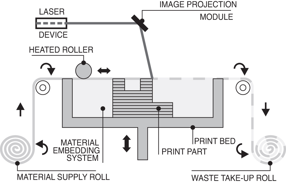
Schematic representation of SHL technology system and process. SHL, Sheet Lamination.
A heated welding roller moves across the sheet and vibrates in such a way that each sheet gets bonded together with the previous until it becomes a solid mass. There are four different ways to achieve bonding between layers, which include ejecting binder between layers, carrying out thermal bonding procedures, clamping, and ultrasonic welding. A basic classification of SHL methods is based on the order in which the sheets are cut and bonded. If the laminate sheet is first bonded with the previous layers and then formed as the predetermined shape, the process is noted as “bond-then-form,” while if the sheet is first formed into the desired layer's outline and then is bonded with the substrate, the method is called “form-then-bond.” In the “bond-then-form” process, the 3D printed part is embedded into a material cube and PPTs are required to get the final object off.
The most popular SHL method is Laminated Object Manufacturing (LOM), using paper sheets as a feedstock. Other SHL technologies are Selective Lamination Composite Object Manufacturing (SLCOM), Plastic Sheet Lamination (PSL), Computer-Aided Manufacturing of Laminated Engineering Materials (CAM-LEM), Selective Deposition Lamination (SDL), Composite-Based Additive Manufacturing (CBAM), and Ultrasonic Additive Manufacturing (UAM). 86 SHL technology has successfully been applied in manufacturing either paper and polymer parts, or metal and ceramics objects. In SHL systems, print resolution is a noneasily optimized factor since it is linked to sheet thickness, which is predetermined and cannot be easily changed. The selection of the “bond-then-form” or the “form-then-bond” process depends on the intended application and can significantly affect the mechanical performance of the final 3D printed part.
The use of color inkjet printing in combination with SHL methods makes the latter able to fabricate directly full-color outputs. The main advantages of SHL technology include the development of low residual stresses and thus low shrinkage and minimal distortion problems, the ability for fabricating large parts rapidly, as well as the stability and nontoxicity of the feedstock, and the relatively low operational and material cost, compared to other AM processes. Moreover, ceramic (CAM-LEM) and composite fiber (SLCOM) parts can be manufactured, while original equipment manufacturer parts, such as sensors and wires, can be embedded into the part during the layering stage. As SHL technology uses standard material and no support structure is necessary, the process cost is relatively low. In addition, SHL systems operate with a larger working table, related to other AM systems, while multiple materials can be applied using UAM technology. Finally, in some cases, excess material can be easily recycled and reused.
Concerning the challenges of SHL technology, layer height cannot be changed, as it depends on the predefined sheet thickness, and additionally, the quality finish can vary depending on paper or plastic material, and thus, postprocessing may be required to achieve the desired effect. Moreover, SHL technologies are compatible only with a limited variety of materials. It can be time-consuming and difficult to remove the excess material after the laminating phase and it generates a lot of waste compared to other AM methods. Moreover, internal voids and cavities show complexity to be produced in “bond-then-form” processes, as the material is formed first as a solid mass. Therefore, bonding strength depends strongly on the applied laminating technique, and, in some cases, adhesive bonds are not effective for long-term product use, strength, integrity, and durability. Finally, material waste can also be high if the part being made is smaller than the build area or the sheet size.
SHL technologies are mainly used in the Automotive and Aerospace industries, Military and Defense, Industrial Manufacturing, and Advanced Microelectronics.87,88 The leading companies invested in SHL technologies, using paper, polymer, or ceramic and metal feedstock, are Cubic Technologies Ltd., Fabrisonic, LLC, Impossible Objects, and Mcor Technologies Ltd., which is in liquidation since 1996, and thus, it is no longer active in trading.
Binder jetting
BJT technology, which was developed in the early 1990s at MIT and commercialized by Z Corporation, refers to the technology for direct digital fabrication, that a binder is sprayed through an extrusion nozzle on successive layers of powder to form a shape defined by CAD specifications. 89 The typical structure of BJT systems consists of a binder feed system, an inkjet print head, a nozzle to jet the binder onto the fabrication platform (i.e., print bed), a powder delivery system, and a compaction roller to smooth the added powdered layers (Fig. 6).
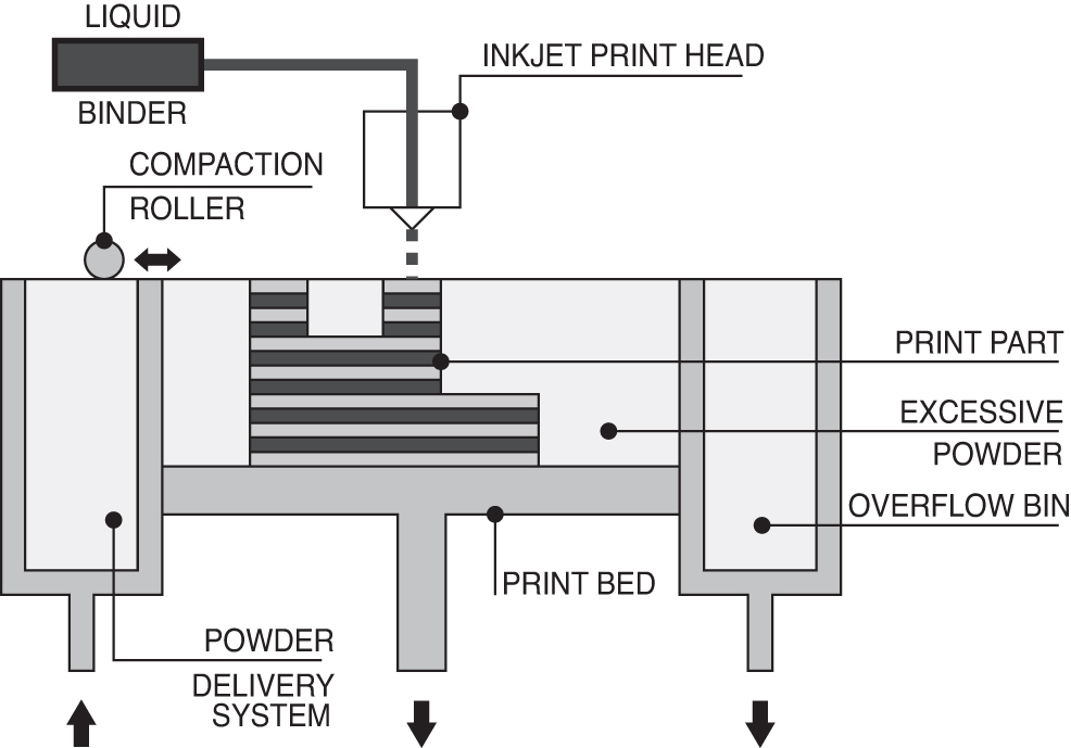
Schematic representation of BJT technology system and process. BJT, Binder Jetting.
In BJT methods, a powdered layer is spread on the build platform and then an inkjet print head moves across it and selectively jets binder solution in droplet form, following the design pattern and causing the powder's grains to coalesce. When the layer formation is complete, the print bed is lowered to the layer's thickness and a new powdered layer is spread on the print bed using a roller mechanism. PPTs are required in this method to improve the surface and mechanical properties, increasing the part's quality and strength. Specifically, the printed part is extracted by brushing away the residual powder, using pressurized air. In metal and ceramic BJT techniques, successive heating processes are occurred to facilitate the part to get fully cured and dried. 90
The original name for BJT methods was 3DP, introduced by the MIT team. Color Jet Printing (CJP) is also another term used for BJT technology, trademarked by Z Corporation. The simplicity of BJT methods allows for processing a wide variety of powder materials, including polymers, metals, ceramics, composites, and bio-inks.18,35 The powdered material used most in BJT is gypsum based in combination with a binder based on water. However, polymer powders and wax-based binders are also compatible with BJT methods. Concerning metal powders, stainless steel, bronze, and Inconel are broadly used in BJT methods. The major factor that impacts the strength, stiffness, and thus lifetime elongation is the type of binder applied. In the case of 3DP methods, the chemistry and the rheology of the binder, the size, and the shape of the powder particles, as well as the deposition speed, affect the interaction between the powder and the binder, and therefore play an important role in the result. The lower the powder cohesion, the better the surface finish and the dimensional accuracy. 53
BJT methods typically have a high deposition speed at a relatively low cost. In addition, there is no need for fabricating support structures, as the powder itself acts as supporting material and thus assemblies and kinematic joints are easy to be manufactured. Moreover, intact powder materials can easily be recycled and reused in subsequent printing processes. A positive powder characteristic is the high material density, which results in high resistance in PPTs, like powder removal and clean-up procedures. The combination of powdered and adhesive materials enables compositions that are not easily achieved with simple extrusion methods. Moreover, there is the possibility for manufacturing metal casting molds, as the powdered pattern can be easily removed from the final part. Finally, the BJT process allows full-color outputs for being fabricated, as multicolored inks can be used effectively. Parts fabricated using BJT technology tend to perform lower quality and surface finish, compared to MJT methods, and PPTs are also necessary to establish high mechanical properties. 91
BJT-fabricated parts due to their built process speed provide a wide range of applications mainly in Automotive and Motorsports sectors, Aerospace and Defense, Jewelry, Shoe industry, Art and Design, Dental and Medical fields, Industrial Manufacturing, as well as Turbomachinery and Serial production.40,57,58,92,93 The leading system developers of BJT technologies are ExOne, Z Corporation (purchased by 3D Systems in 2011), Voxeljet, Microjet Technology, Digital Metal, HP Metal Jet (HPMJ), and GE Additive.
Directed energy deposition
DED is an AM technology, invented in 1995 by Sandia National Laboratories and commercialized by Optomec Design Company, which applies a heat source for fusing a powdered or a wire-based material as it is extruded by one or more nozzles. A typical DED system consists of one or more extrusion nozzles, attached to corresponding print heads, an energy source unit, an image projector module, and a fabrication platform (i.e., print bed) (Fig. 7).
Schematic representation of DED technology system and process. DED, Directed Energy Deposition.
Although the DED process uses powdered materials as feedstocks, it is similar to extrusion-based methods. The difference between DED and PBF technology is that in the first case, instead of a compaction roller to add and smooth the build powder, there is a nozzle that deposits the melted material—like the FDM method—on the print bed. Then, the energy source moves across and makes the material solid. In DED technology, when the laser beam is focused on small spot size, there is a region above and below the focal spot, where the laser energy density is high enough and forms a molten area. DED print head creates first the outline of the part and then adjacent lines of material form the internal layer pattern. This process is repeated until the 3D printed part is fully built. This technology can be used not only for fabricating new complete objects but also for replacing and repairing worn or damaged existing parts as it can deposit simultaneously multiple materials, moving across multiple axes.
DED technology can be grouped into two categories depending on the feedstock material form. Specifically, either powders or a wire can be applied as a process feedstock. Powder-based DED methods are Laser Engineered Net Shaping (LENS), Laser Solid Forming (LSF), Directed Light Fabrication (DLF), Laser Metal Deposition (LMD), Laser Deposition Welding (LDW), 3D Laser Cladding, Laser Generation, Laser-Based Metal Deposition (LMBD), Laser Freeform Fabrication (LFF), laser Direct Casting, LaserCast, Laser Consolidation, and LasForm. Wire-based DED methods are Electron Beam Additive Manufacturing (EBAM) and Wire and Arc Additive Manufacturing (WAAM), while Direct Metal Deposition (DMD) implements the combination of powdered and wire feed materials.3,53,94–96 LMD technology has also been developed with a wire-based feeding system using the term LMD-w. 95 Although the basic operational principle is similar, differences between these technologies commonly include changes in laser power, laser spot size, laser type, powder delivery method, inert gas delivery method, feedback, and motion control method.
DED processes aim to produce fully dense functional parts. Build materials, in the form of powder or wire, include steel, copper, aluminum, nickel, titanium, and other high-performance superalloys. Metals with high reflectivity and thermal conductivity are difficult to process, while metals with good weldability are easily manageable. In addition, ceramics, mainly as a part of ceramic or metal composite, as well as polymers can also be used in DED systems.
There are various parameters of optimization, which participate in DED methods. Important process parameters include scan patterns, focal spot, scan rate, beam power and size, powder feed rate, and surface morphology. These factors affect the layer thickness, which is determined more precisely after the formation of some successive layers. The first few layers may have a different width than the setting of the operator. The scan orientation between layers can minimize the development of residual stresses and thus also improves the mechanical performance of the final part. As solidification rate and thus microstructure and mechanical properties can be controlled, the surface of molten material can be monitored and controlled by dynamically changing laser power.
DED is commonly used for fabricating components with large size and low complexity, as it is characterized by high speed and extended print tables. Moreover, it can reduce the manufacturing cost, providing excellent mechanical properties, controlled microstructure, and accurate composition control.53,97 DED technology allows for the combination of metal alloys or ceramics and as a result, more materials can be extruded at the same time.
DED can be easily combined with conventional processes and minimize the degradation of mechanical properties caused by thermal stresses. They also can repair any damage, improving their quality performance and lifetime. This procedure is processed with lower fabrication cost, greater build capability, less waste, faster operation period, energy-saving, and low weight.10,46 In the case of powdered feed systems, a high material yield is achieved, as the residual powder can be reused and recycled. 94 Excess powder feeding makes DED processes geometrically flexible. As in all AM processes based on the extrusion method, in DED, each successive layer is typically deposited in a different orientation than the previous one, and thereby anisotropic properties and residual stresses are minimized. DED offers the ability to change the material composition by simply changing powder feeder mixtures and process parameters, and thus, the microstructure control can be achieved, increasing the design freedom.
DED technologies cannot manufacture high-complexity parts, as PBF methods do, because they have lower dimensional accuracy and lower surface quality. As DED is multimaterial technology, additional care must be taken to control the undesired interaction between the different in-contact materials. The formation of brittle intermetallic phases formed between dissimilar materials in combination with residual stresses can lead to undesired cracking. For EBAM methods, the technology is limited to single-material printing. Parts fabricated using DED technologies perform rough surface finish and as a result, postprocessing procedures, like machining or polishing, may be necessary. Stress relief HT may also be required to release residual stresses and produce the desired microstructure.
DED technology is widely used for filling cracks and retrofitting already manufactured parts for Aerospace and Automotive Applications. Using DED methods, existing structures can improve their performance and extend their lifetime. Moreover, this method is highly studied by researchers to invent and develop new and advanced materials related to new industries. Other fields of application are referred to Dental and Medical industry, Air conditioning and Energy technology, Construction, Displays, Component Repair, Sheet Metal Processing, Electronics, Science, Tool and Mold making, as well as Photovoltaics and Hybrid Manufacturing.43,50,94,95,98 The leading manufacturers and suppliers of DED systems are Sciaky, Trumpf GmbH, Optomec, Prodways, RPM Innovations, Formalloy, Raycham, and AlphaLaser.
Material jetting
MJT technologies, which create 3D objects in a similar way to a typical 2D inkjet printer, were introduced and commercialized in 1994 by Sanders Prototype (now Solidscape). A typical MJT system consists of one or more extrusion nozzles, attached to corresponding print heads, a liquid feeding system, an energy unit, and the fabrication platform (i.e., print bed) where the part is built (Fig. 8). MJT methods can be grouped into two categories: wax-feed and liquid-feed technologies. In wax-feed technologies, the print head jets molten wax-based material onto the print bed, which is then cooled and solidified. In liquid-feed technologies, the print head jets liquid photopolymer suspension onto the print bed, which is immediately cured by a UV light to be evaporated and finally solidified. 53 Initially, the feedstock in wax-feed technologies, which is in the solid state, is heated to be converted into liquid and then the material is deposited on the print bed through one or more nozzles and is exposed to UV light to promote photopolymerization.
Schematic representation of MJT technology system and process. MJT, Material Jetting.
In MJT methods, there are two types of material extrusion. If the material ejects like a continuous liquid, the deposition refers to a continuous Stream process; while if the material extrudes from the nozzle as discrete droplets, the process is referred to as drop-on-demand. 10 MJT technologies have developed control systems to monitor and evaluate the nozzle performance during the process. Circular cleaning procedures and complex sensor systems have been planned and developed to purge the nozzles regularly and maintain them open, while additional nozzles are available in case of clogging.
There are a variety of terms describing the MJT methods, such as MultiJet modeling, Inkjet printing, Thermojet, PolyJet modeling, Polyjetting, Multijetting, Multi-Jet-Printing (MJP), MultiJet, E-jet, Jetted Photopolymer, MultiFab, Contour Printing, 3D Concrete Printing (3DCP), Contour Crafting (CC), and Bioprinting.3,5,53,99,100 PolyJet, trademarked by Stratasys Ltd., is the most established MJT method, which uses wax material for support structures, while MultiJet technology, defined by 3D Systems, accepts water-soluble photopolymers as a support material. 30 A new MJT technology, called Nanoparticle Jetting (NPJ), is growing, which permits the direct 3D inkjet printing of highly detailed metal parts. CC technology is capable of extruding concrete paste and is the main method of AM for large building structures.83,101–107 Bio-printing is the technology used for in situ generation of tissues, developing models for toxicity tests, disease models, and testing adverse reactions to drugs.
The materials, which are mainly used in MJT methods, are waxy and acrylate polymers, as well as ceramics and metals. The particle size distribution, the material's viscosity, the extrusion rate, the nozzle size, and the printing speed are factors that determine the quality of the inkjet-printed parts. 108 Basic parameters that affect the droplets' deposition and thus the printing quality are the specific point where the droplet deposits on the build platform, the droplet size, the droplet speed, as well as the nozzle design and operation. In addition, the timing and the position where the droplet solidification occurs affect the interaction between the droplet and the substrate, and thereby the final deposition quality.
Other influential factors are the liquid density, the surface tension, the speed of scanning and jetting, the print head speed, the droplet deposition frequency, the solidification contact angle, the scan speed, the drop-to-drop spacing, and the substrate material. For MJP and PolyJet methods, except for the factors mentioned above, the accuracy is affected by the PPTs, including support removal, UV curing, and surface smoothing, while the ambient temperature, the humidity level, and the mechanical vibration are additional parameters referred to machine errors. 99
A single part, printed using MJT technologies, can combine a variety of mechanical properties, opacities, and colors. 109 The primary advantages of MJT include high resolution, high speed and efficiency, scalability, ease of building parts in multiple materials, and the capability of printing multiple colors.5,10,53 High speed and scalability are related, as the use of print heads with multiple nozzles is possible to facilitate the quick deposition of a large amount of different material over a considerable area. In CC technology, the main benefits observed are the reduction of construction time, manpower transportation costs, and material wastage.
MJT is an extremely complex process, with challenging technical issues, such as the transformation of wax feedstock into a liquid state to be able for jetting. Maintaining flowability and thus workability, as well as lack of adhesion between layers are the main drawbacks of this method. Another hurdle is to convert the liquid material into discrete droplets, which depends on the material's physics, the hardware involved, and the process parameters. A third challenge is the control of droplets' deposition, considering the movement of either the print head or the substrate platform. The deposition process may lack uniformity, creating warpage and other undesirable results. Moreover, nozzle blockage may occur, preventing droplets from jetting. For wax-feed technologies, there is no other material type available and compatible with this 3DP system, while for liquid-feed methods, the UV active photopolymer materials are not durable over time, and they should have similar curing temperatures.
Inkjet printing is gaining more attention in bioprinting applications and is specifically used for manufacturing complex and advanced ceramic scaffolds for tissue engineering. 110 In addition, CC technology is used in the Construction industry. 83 Other applications for MJT technologies include Rapid Prototyping, Art and Fashion, Aerospace and Automotive, Jewelry, and Eyewear manufacturing.40,81,92 The leading manufacturers and suppliers of MJT technologies are Stratasys Ltd., 3D Systems, Inc., Luxexcel, Solidscape, Inc., by Prodways, 43 ExOne, Xjet for NPJ systems, and Cellink 110 for biofabrication with hydrogels and bio-inks. 35
Double-Level Classification Models
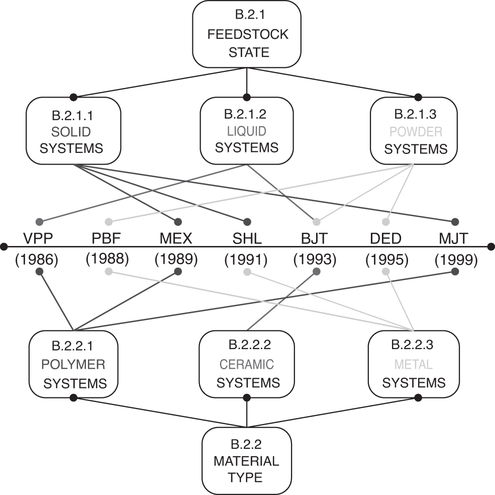
A comprehensive overview of AM technology processes, sorted in chronological order, has been presented in A Historical Snapshot of AM Processes section. Through the knowledge grouping method, a multilevel classification model of AM technology systems has been proposed, referring to either the technology (Fig. 9) or the material characteristics (Fig. 10). The term “technology” describes the specific AM machine structure with the corresponding fabrication process, while the term “material” describes the feedstock used in each AM system.

The proposed technology-related classification model.
The proposed material-related classification model.
Concerning the technology factor, there are systems either container joined or nozzle joined, according to the feedstock mechanism, which is intended for material deposition onto the built platform. In addition, related to technology, there are multistep and single-step processes, depending on the degree to which postprocessing procedures are required. To simplify the grouping process, cleaning up, powdering-off, and washing procedures are not included in approved PPTs, as they do not directly affect the final printing quality. Figure 9 presents ISO/ASTM processes, chronologically sorted, proposing a double-level classification model referred to technology, according to feedstock mechanism and postprocessing requirements.
As shown in Figure 9 (B.1.1), container-joined technologies were first invented and researched for AM processes. Specifically, VPP and PBF technologies, which use a curing device in their systems, have been grown first, while the development of nozzle-joined systems followed later. Container-joined systems in combination with the use of high energy sources were fundamental elements of 3DP systems and their evolution occurred more rapidly, as different energy sources were constantly applied and tested. Since container-joined systems were fully structured, the research interest seems to be focused on new material testing, rather than process enhancements.
On the other hand, nozzle-joined systems, although have initially been invented using MEX technology, just a few years later, did not perform a continuous, steady high growth rate, as their evolution did not occur directly. The concept of nozzle-joined systems was strongly empowered by the integration of containers into them, applying simultaneously the use of a high energy source. Once the containers' integration into nozzle-joined systems happened through BJT technology in 1993, nozzle-joined systems have evolved rapidly, as previously seemed to be nonflexible for material testing and improvements.
Similar conclusions emerge from the classification of ISO/ASTM technologies into multistep and single-step processes (Fig. 9, B.1.2). VPP and PBF technologies, which have been first invented, presented high requirements for PPTs to improve the general quality of final products. Introducing MEX technologies, the concept of direct fabrication with no need for postprocessing was highlighted to simplify the printing process and reduce fabrication time. Although fabrication time is a crucial issue, as it can also reduce total manufacturing cost, it has been proved that required PPTs provide to final products improved surface and mechanical properties, contributing substantially to its quality upgrade. In addition, it is also important to clarify that single-step processes are combined with nozzle-joined systems, while multistep processes refer to container-joined AM systems.
Concerning the material factor, there are three categories, according to feedstock state, that is, solid-feed, liquid-feed, and powder-feed systems. In addition, related to the material type, three groups are also classified, depending on the material type, that is, polymer-based, ceramic-based, and metal-based systems. Figure 10 presents ISO/ASTM processes, chronologically sorted, proposing a double-level classification model referred to material, according to feedstock state and material type.
Concerning the proposed classification, which refers to materials, there is no strong correlation between technologies' history timeline and feedstock state or material type. The option of testing multiple materials has highly attracted research interest; however, it does not seem to provide any influence on AM technology enhancements. Although a wide range of materials is nowadays adopted by all technologies, there is a single material for each one, which is mainly used and provides the best quality results so far. Figure 10 presents the basic built material for ISO/ASTM technologies, without excluding the further use of other materials. The first material that has been used in 3DP was polymer resin. Then, metal in powder state was applied in PBF method, while ceramics were researched and used as feedstock at last, compared to polymer and metal materials. At this point, it is noteworthy that metal materials are more concerned with powder format and are not available in a liquid state, which means that resin technologies are nonmetal AM processes. Respectively, polymer technologies are nonpowder technologies as polymer materials are found in liquid or solid state, such as resins, filaments, or sheets.
In summary, it could be mentioned that a vat mechanism in a typical AM system seems to be an important element, as better 3DP quality and results could be achieved. Container-joined technologies were first invented, while the development of nozzle-joined systems followed later. The concept of nozzle-joined systems was strongly empowered by the integration of containers into them, applying simultaneously the use of a high energy source. Container-joined systems usually require further postprocess curing to upgrade the mechanical properties of the 3D printed parts. Multistep processes have been first invented, presenting high requirements for PPTs, while single-step processes are not so widespread. The concept of direct fabrication with no need for postprocessing was highlighted to simplify the printing process and reduce fabrication time and cost. However, the material criterion did not show a strong involvement in the development of AM processes.
Discussion
The ongoing crisis caused by the COVID-19 pandemic and the Russia-Ukraine military conflict has greatly affected business operations, 1 which are investing in innovative resources and processes to overcome the disruption and continue to operate effectively in the “new normal” era. The process of global transformation posed by these urgent events is still in progress, and it appears complex, intense, and rapid; therefore, businesses, to overcome the crisis and survive, should become more agile, and empower their adaptability, their competitiveness, and their resilience.111,112 They should be able to react rapidly to market opportunities, arising problems, and new trends, facilitating readjustments in structure and work routine and introducing new methods in the production and customer service approach. The capacity of the business to respond effectively to harsh conditions through internal reconfiguration and external partnership empowers the business resilience, agility, and flexibility and improves its ability to rapidly change management direction and adapt different resources amidst emergencies and deep imbalance. 111
The preventive measures and socioeconomic challenges of COVID-19 and the Russia-Ukraine military conflict, such as the widespread lockdown, the social distancing, the expected psychological burden, the subsequent reduction in consumption and investment, as well as the disruption of Ukraine's supply, and the Russian trade isolation, created conditions for the digital transformation of businesses, spreading the industry 4.0 concept and accelerating technological modernization.112–114 Businesses were urged to research and develop new, innovative, dynamic, and effective organizational systems, re-focusing their management framework to achieve both existing and new goals. 115 In addition, the COVID-19 pandemic allowed business owners to further specialized educational orientations, technical skill improvement, and knowledge broadening, 1 highlighting the contribution of 3DP technology in crisis management and increasing its industrial applications.
3DP technology emerged as a preferable solution for supply chain interruptions posed by the COVID-19 pandemic, as it could cover the large demand for easily adjustable medical devices with minimum personal interaction and no complex planning and infrastructure.116,117 The evolution of 3DP technology seems to be continuous and increasing. The various 3DP processes do not produce the same outputs, as each provides different appearance effects and mechanical properties resulting in different quality results.
In particular, the VPP, PBF, and MJT processes can manufacture more complex geometries, as they exhibit high print resolution, while the MEX and DED processes are not suitable for building highly complex parts, as they have lower dimensional accuracy. In addition, VPP offers excellent precision and excellent surface finish quality, while all other processes require PPTs to improve the appearance of their outputs. In terms of mechanical properties, the SHL and DED methods provide better strength and durability, compared to VPP, PBF, and MEX processes, which exhibit greater deformation and anisotropic issues. Regarding cost-effectiveness, the PBF, MEX, SHL, and BJT processes provide relatively low operational costs, while the main challenge for the VPP method is the high manufacturing cost and limited materials applied. The low variety of materials is also evident in the MEX and SHL processes, in contrast to the PBF method, in which a wide range of materials is used. Table 2 summarizes the main advantages and limitations of each 3DP process.
A Comparison of the Main Advantages and Limitations of the Additive Manufacturing Processes
The interest of researchers and enterprises is manifested through the constant research of new technologies, the introduction, and testing of different materials, as well as the wide expansion of industrial applications. This article, considering the technology and the materials as main criteria for 3DP revolution, examined the extent to which they influence the development of AM technology. Specifically, a systematic literature review of AM technologies, chronologically sorted, was presented and a multilevel classification model was suggested, related to technology and materials, respectively. Concerning the technology, a double-level classification was related to the feedstock deposition mechanism and the degree to which postprocessing procedures are required. Concerning the materials, the AM technologies were organized according to feedstock state and material type.
This article aimed to examine the correlation between the proposed classification model and the evolution timeline of AM technologies. According to the technology-related classification, a relative connection between the timeline and the AM subcategories appeared to be consistent. According to the material-related classification, no strong correlation between technologies' timeline and feedstock state or material type was achieved. The option of testing multiple materials had highly attracted research interest; however, it did not appear to provide any influence on AM process enhancements.
The lack of similar previous research studies, as well as the continuous technological tests and improvements of 3D systems and processes, had placed limitations on our research field. In particular, the materials' criterion, which did not provide sufficient conclusions as to its status and type, may need to be reformulated and re-examined, as it is considered crucial for print quality and mechanical system performance, as well as error and deviation prevention. Systematic studies for the clarification of benefits and challenges of each proposed AM category are recommended for further research, as an additional interconnection between the suggested categories and subcategories will confirm the reliability and validity of our proposed classification model and enrich the knowledge distribution in the field of 3DP technology.
To transform the proposed approach into a successful decision support system for AM ecosystem stakeholders undergoing technology changes, several additional steps are required. These include collecting data on the characteristics of the AM application that someone wants to invest in, analyzing the industrial sector and fabrication processes to be used, and determining the optimal machine in terms of feedstock and materials.
Conclusions
In this article, the research interest was focused on exploring the key factors that affect the evolution of 3DP technologies over time. Two main criteria were primarily discussed, referring to the technology and the materials. Applying systematically our methodology approach, a multilevel classification model of standard AM technologies was proposed. Finally, a correlation between technology and time evolution was found, while no interconnection between time and materials had been approved.
The suggested classification model aimed to create a reliable framework on which the comparison between AM technologies with similar characteristics can be carried out. This classification framework, in combination with the factors that affect the quality result of each AM process, contributes to the development of a valid methodology for connecting each technology with different applications. However, due to the ongoing development of 3DP, there is no classification of AM processes using the criterion of their industrial applications, as research and testing in different sectors are constantly changing. A detailed clarification and subsequent categorization of industrial applications for each AM technology could be considered a creative solution to generate new perspectives, patterns, or relationships between 3DP technology and manufacturers.
Footnotes
Authors' Contributions
M.K.: conceptualization (lead); formal analysis (lead); project administration (equal); investigation; methodology; writing—original draft; and writing—review and editing (supporting). M.M.: conceptualization (supporting); formal analysis (supporting); project administration (equal); supervision; validation; and writing—review and editing (lead).
Author Disclosure Statement
The authors have no relevant financial or non-financial interests to disclose. The authors have no conflicts of interest to declare that are relevant to the content of this article.
Funding Information
This research received no specific grant from any funding agency in the public, commercial, or not-for-profit sectors.