
Abstract
With the development of science and technology, flexible sensors play an indispensable role in body monitoring. Rapid prototyping of high-performance flexible sensors has become an important method to develop flexible sensors. The purpose of this study was to develop a flexible resin with multi-walled carbon nanotubes (MWCNTs) for the rapid fabrication of flexible sensors using digital light processing additive manufacturing. In this study, MWCNTs were mixed in thermoplastic polyurethane (TPU) photosensitive resin to prepare polymer–matrix composites, and a flexible strain sensor was prepared using self-developed additive equipment. The results showed that the 1.2 wt% MWCNTs/TPU composite flexible sensor had high gauge factor of 9.988 with a linearity up to 45% strain and high mechanical durability (1000 cycles). Furthermore, the sensor could be used for gesture recognition and monitoring and has good performance. This method is expected to provide a new idea for the rapid personalized forming of flexible sensors.
Introduction
With the development of science and technology, wearable devices containing numerous sensing elements have brought great changes to our lives. Wearable flexible sensors provide important information about human health status in a timely and economical manner by measuring the human behavior parameters and sensing the surrounding environmental indicators, which have a positive impact on human health. 1 Polymer–matrix composites with excellent flexibility are not only widely used as carriers for flexible electronic devices, but also conductive polymer composites constructed based on them are used to prepare flexible pressure, strain, and other sensors.2–8
Flexible sensors are suitable for different sensing principles. Commonly used preparation methods include liquid phase mixing method, chemical vapor deposition method, coating method, spin coating method, compression molding, and electrostatic assembly.9–11 Gao and colleagues used carbonized melamine sponges to fabricate wearable flexible sensors. 12 Liang et al. used a covalent assembly-annealing strategy to prepare nitrogen-containing covalently cross-linked graphene foams with excellent compressibility and electrical conductivity. 13 These traditional manufacturing methods have certain disadvantages such as long processing cycles and difficult fabrication of composite polymer microstructures. Additive manufacturing of the polymer-based flexible sensors has become a current research hot spot and has broad development prospects.14–16
The commonly used additive manufacturing materials for flexible sensors include carbon nanocomposites, metals and composites, liquid metals, and PVD polymers. 17 Among them, carbon materials are inexpensive and easy to fabricate due to their excellent electrical conductivity, mechanical properties, chemical stability, and thermal stability. In recent years, with the development of advanced carbon materials with unique dimensions such as one-dimensional carbon nanotubes and two-dimensional graphene, carbon materials have become a research hot spot for flexible strain sensors.18–22 Furthermore, carbon nanotubes are used for the development of multifunctional composite materials with their excellent mechanical and electrical properties.23,24 Furthermore, high aspect ratio multi-walled carbon nanotubes (MWCNTs) with low percolation threshold enable low-cost and high-sensitivity flexible sensor fabrication. 20
Presently, additive manufacturing is widely used in the manufacturing of metal parts, cell culture chips, scaffolds for tissue engineering, 25 and medical aids.26–28 Among them, digital light processing (DLP) printing technology has small curing shrinkage, high printing accuracy, excellent surface quality, fast processing speed, and no emission of harmful gases during the curing. It can also process samples with complex structures and has a wide range of applications. 29 Wu and colleagues fabricated self-healing three-dimensional (3D) smart structures using DLP additive manufacturing technology, providing a unique strategy for 3D smart composites. 30 Thermoplastic polyurethanes (TPU) have high elongation and good affinity with the carbon fillers, 31 and the fabrication of TPU-like conductive polymer-based strain sensors is widely used. 32 However, there are only a few studies on photocuring forming of carbon nanotube/TPU composite flexible sensors.
In this work, high aspect ratio (tube length/diameter 3000) MWCNTs were uniformly dispersed in TPU photosensitive resin material using stirring and ultrasonic vibration, and the rapid prototyping of flexible sensors was realized using photocuring molding. The distribution of the carbon nanotubes in conductive polymers was further studied using field emission scanning electron microscopy (SEM) and Raman spectroscopy. The strain sensing behavior of the flexible sensor was analyzed using a digital bridge combined with a universal testing machine. From the results, it was found that the highest sensitivity of the fabricated sensor was 9.988, and the stability of the sensor was evaluated using cyclic stretching. The fabricated sensor is also found to satisfy 1000 stretching cycles and is used to monitor human movements.
Experimental Section
Materials
TPU photosensitive resin was purchased from Dongguan Shenshuo Technology Co., Ltd.; MWCNTs (diameter 10–20 nm, tube length <50 μm, purity >99.5%) were purchased from Shenzhen Yuechuang Evolution Technology Co., Ltd.; dispersant DISPERBYK-163 was purchased from Shanghai Kane Chemical Co., Ltd.; and ultraviolet (UV) thinner TPGDA was purchased from Shanghai Kaiyin Chemical Co., Ltd.
Preparation of composite material slurry
A certain amount of MWCNTs is added to the TPU photosensitive resin, and the weight percentage of MWCNTs is controlled at 0.1%, 0.3%, 0.5%, 0.7%, 0.9%, 1.1%, and 1.2% (sample names are TPU, TPU-0.1, TPU-0.3, TPU-0.5, TPU-0.7, TPU-0.9, TPU-1.1, TPU-1.2). When adding, the dispersant leveling agent is evenly added to the resin. The mixture was stirred in a YM-100S3 ultrasonic cleaner (Shenzhen Fangao Microelectronics Co., Ltd.) using a LC-ES-60 digital display mixer (Shanghai Lichen Instrument Technology Co., Ltd.) at 1200 rpm to obtain a composite material slurry. The preparation process was carried out in a dark environment.
Manufacture of strain sensors
The composite material slurry was placed in a self-developed photocuring forming equipment, the UV light intensity was 50 mW/cm2, the printing layer thickness was 0.1 mm, and the exposure time was 40 s. After forming, the samples were cleaned in isopropyl alcohol cleaning solution for 2 min and then placed in a UV box for secondary curing for 5 min. After curing, the copper sheets are glued to both ends of the sample, and the copper wires are connected to complete the fabrication of the sensor.
Figure 1 shows the preparation process of the material and the principle of photocuring molding. The MWCNTs are uniformly dispersed in the TPU resin by stirring and ultrasonic vibration. The surface morphology of the formed samples was characterized by SEM, and the prepared samples were electrically measured by a digital bridge. All measurements were performed in air and at room temperature.

Schematic diagram of forming.
Performance characterization
The morphologies of MWCNTs, TPU, and MWCNTs/TPU composites were characterized by field emission SEM (Hitachi Regulus 8220). The chemical composition of MWCNTs, TPU, and MWCNTs/TPU was investigated using Raman spectrometer (Horiba Scientific-LabRAM HR Evolution, ion laser at 514 nm). These composite samples were measured with a digital bridge (RK2830; Shenzhen Merrick Electronic Technology Co., Ltd.) and a multimeter [UT60BT; Uni-Trend Technology (China) Co., Ltd.] resistance of the piece. The stress–strain curve and electromechanical properties of the strain sensor were measured by a universal material testing machine (China-Sansi Zongheng-UTM2203) and a digital bridge (RK2830; Shenzhen Meiruike Electronic Technology Co., Ltd.).
Conductivity is calculated according to Equation (1)
33
:
where L is the distance between the two probes, R is the ohmic resistance measured by the digital bridge, and A is the cross-sectional area of the sample.
The sensitivity coefficient (gauge factor [GF]) of the sensor is calculated by Equation (2):
Here, ɛ is the strain of the sensor, and
Results and Discussion
The results of liquid conductivity of MWCNTs/TPU composites with different contents, characterization of photocurable forming conductive composites, sensing properties of composite materials, and the potential applications of the flexible sensors based on MWCNTs/TPU are briefly described below.
Liquid conductivity of MWCNTs/TPU composites with different contents
In this work, a multimeter was used to test the change of the resistance of the liquid composite material with the ultrasonic vibration time. Figure 2a shows the schematic diagram of the measurement. The measurement results are shown in Figure 2c, and from the figure, it is observed that with the increase of ultrasonic vibration stirring time, the liquid resistance gradually decreases and finally stabilizes. The optimum ultrasonic vibration stirring time is found to be 20 min. After the curing, the resistance of the sample was measured using Figure 2b, and the resistivity was calculated as shown in Equation (1). The results are shown in Figure 2d.
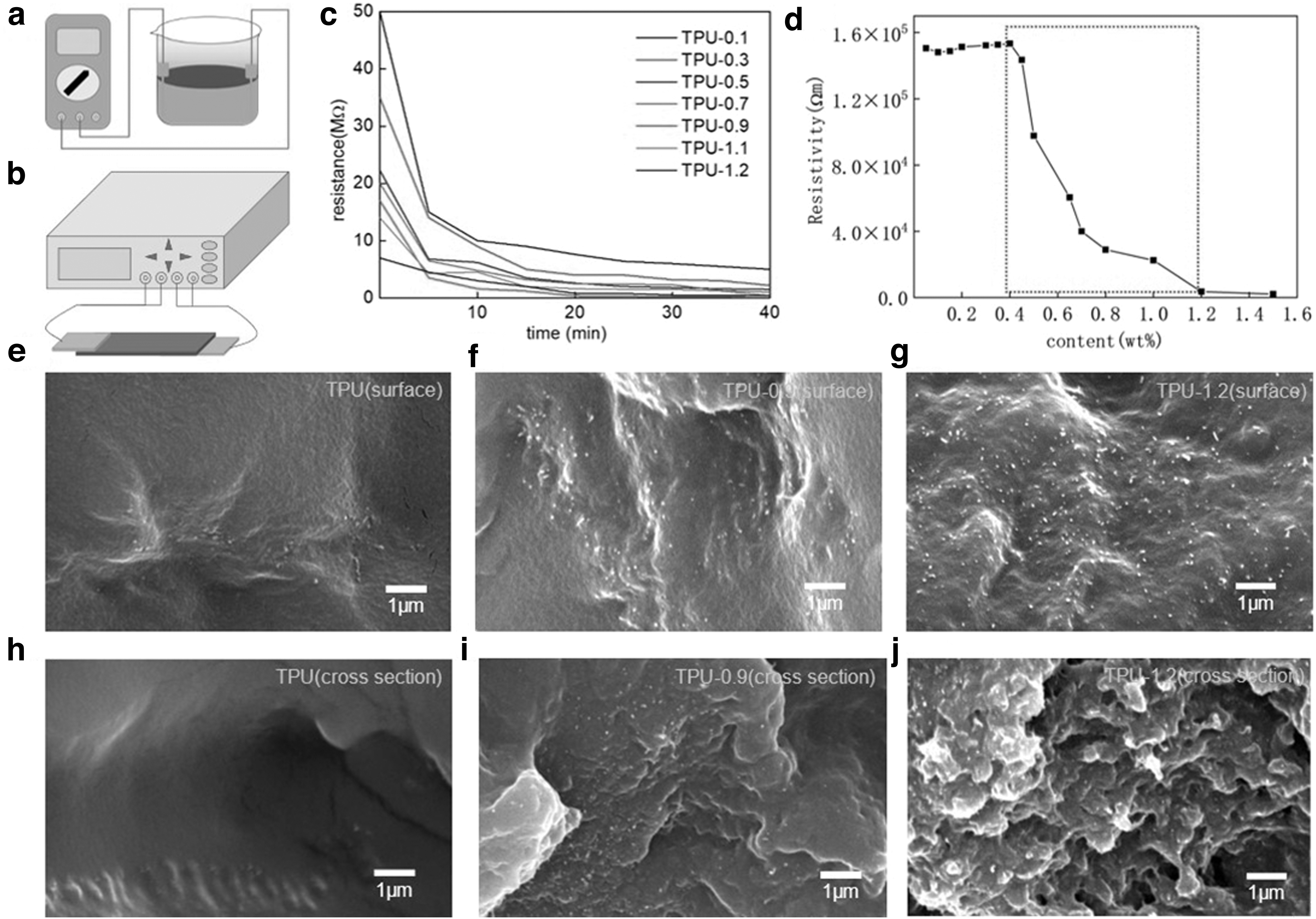
Electrical measurement method and characterization of MWCNTs/TPU composites.
Figure 2d shows that the resistivity of the composite decreases with the increase of MWCNT content; however, it is not a simple linear relationship. The red line area is the seepage area, which is consistent with the literature.34,35 Furthermore, according to the Ponte Castaneda–Willis model, the percolation threshold of MWCNTs is found to be about 0.3 wt%, which is close to 0.4 wt% in the experiment, indicating that MWCNTs are well dispersed in TPU. Figure 2e–j shows the SEM images of the surface of the MWCNTs/TPU samples at different concentrations and the SEM images of the pure TPU. The bright filamentous and punctate parts in the figure are the distribution state of MWCNTs in the resin, indicating that the MWCNTs are uniformly dispersed in the TPU.
Characterization of photocurable forming conductive composites
Figure 3a shows that the TPU characteristic peaks at 1294, 1458, 2870, and 2930 appear in the Raman spectrum of TPU. The peak at 1294 is the stretching vibration of the C = C double bond, and the peak at 1458 is attributed to the deformation of C-H. Furthermore, the observed bands are found to originate from C-H stretching vibrations, where 1348 is the D-band, 1594 is the G-band, and 2697 is the 2D-band for MWCNTs. Raman bands assigned to TPU and MWCNTs are observed for TPU/1.2MWCNTs, and it is considered that MWCNTs penetrate well into TPU.

Mechanical and electrical properties testing and results of MWCNTs/TPU composites.
The mechanical tensile test was carried out using the formed tensile samples. 36 Figure 3b plots the comparison of the tensile properties of composites with different contents of MWCNTs, and Figure 3c shows the stress–strain curve. From the figures, it is found that the trend is consistent with the literature 37 Furthermore, the test results showed that with the increase of MWCNTs content, the elastic modulus initially increased and then decreased, and the elongation at break showed a decreasing trend as a whole. It is also observed that Young's modulus of the composite increases from 1.053 to 2.331 MPa when the MWCNT content is 0.5 wt%, an increase of 121%.
Moreover, the MWCNTs are uniformly dispersed in the TPU, and the hydrogen bonding between the MWCNTs and the TPU matrix is found to result in a strong interfacial bonding force between them. 38 The increase in Young's modulus may be due to the high stiffness of MWCNTs and the stronger interfacial bonding between MWCNTs and the matrix. Furthermore, with the increase of MWCNT content, the agglomeration will also increase. The internal defects of the MWCNT-based composites are found to increase with the increase of the content of MWCNTs, resulting in a decrease in elongation at break. Moreover, with the increase of MWCNT content, the degree of freedom of the TPU macromolecular chain is limited to a certain extent. 35
Figure 3d shows the sensitivity of the sensor with different contents of MWCNTs/TPU. The results showed that with the increase of MWCNT content, the sensitivity of the device showed an upward trend, and the highest sensitivity GF was obtained as 9.988 at 1.2 wt%. Moreover, the maximum detectable strain was found to be 45%, and it had good linearity within 45% deformation. Furthermore, at low levels, it is observed that there are fewer conductive channels, and when strain is applied, the channels are less on and off, exhibiting less sensitivity. Figure 3e shows the response time and recovery time of the sample tested at a high tensile rate of 1000 mm/min under a small strain of 5%. The results show that the response time of the composite is 400 ms and the recovery time is 1200 ms. The longer recovery time may be due to the hysteresis of the material itself. Figure 3f compares the performance of the sensor prepared in this study with the current study. The relevant data are shown in Table 1.
Comparison of Sensor Performance
CNT, carbon nanotube; EA, elastomer; EGaIn, Gallium–indium eutectic; ER, elastomer resin; FCMS, fragmented carbonized melamine sponges; MWCNTs, multi-walled carbon nanotubes; PANI, polyaniline; PDMS, polydimethylsiloxane; RGO, graphene oxide; SEBS, Styrene-ethylenebutylene-styrene; TMTCW, Name of a product of Zhilei Electronics And Technology (Wuhan) Co., Ltd; TPU, thermoplastic polyurethanes; UV, ultraviolet.
Sensing properties of composite materials
Figure 4a and bshows the physical drawings and drawings of the tensile sample, respectively. Figure 4c and d demonstrates the good flexibility of TPU-1.2 composites, respectively. Figure 4e shows the cyclic loading stress–strain curves of the three MWCNTs with a tensile specimen type variation of 45%. From the figures, it is observed that TPU-0.3 and TPU-0.9 have large plastic deformation and poor elasticity in the loading and unloading stage, and TPU-1.2 shows good elasticity. It is also found that after a certain number of cyclic stretching, the internal structure of the TPU-1.2 composite tends to be stable, and the mechanical response behavior has good repeatability and recoverability.44–46

Cyclic tensile test results of MWCNTs/TPU composites.
Mechanical durability is an important characteristic to ensure the long-term usability of strain sensors, 22 and Figure 4f illustrates the resistance response curve of TPU-1.2 composites cycled 1000 times at the same tensile speed. Figure 4f illustrates the cycling stability of the DLP 3D-printed sensor based on the MWCNT content of 1.2 wt% under 15%, 30%, and 45% strain conditions. The results indicate that the developed strain sensor has high mechanical durability. Furthermore, the sensor resistance showed a trend of increasing first and then decreasing. This may be due to the fact that during the stretching process, the MWCNTs in the MWCNTs/TPU composite, the MWCNTs in the matrix are rearranged along the stretching direction, and the conductive channels parallel to the stretching direction will increase due to the larger aspect ratio and winding structure. Moreover, due to the after-effect caused by the viscoelastic behavior of the composite, during the stretching–shrinking cycle, an optimized conductive network was gradually formed, leading to final stabilization.
Figure 4g shows an enlarged view of a portion of Figure 4f, showing a clear right shoulder. This may be because there is competition for the destruction and remodeling of the conducting channel. Furthermore, the change mechanism is shown in Figure 5. In the initial state, Figure 5a corresponds to the conductive network shown in Figure 5d. It is observed that during the initial state, the uniformly dispersed MWCNTs overlapped each other to form stable and efficient conductive paths. When the material is in a stretched state, as shown in Figure 5b corresponding to the conductive network shown in Figure 5e. The MWCNTs stretched with the movement of the TPU molecular chains, leading to the destruction of some conductive channels, and the distance between the conductive fillers is found to increase leading to the disconnection of the network (indicated by the red area).

Variation mechanism of tensile strain and conductive network of MWCNTs/TPU composites under various strains.
According to the tunnel effect model of resistance, increasing the distance between conductive fillers reduces the probability of electron transitions, resulting in an increase in the resistance value of the material. 47 At the same time, the MWCNTs will re-lap together to form a new conductive network and generate new conductive channels (green area). The destruction of the conductive channels during the stretching process is dominant, so the resistance value of the composites shows an increasing trend during the stretching process. After returning to the initial position as shown in Figure 5c, the corresponding conductive network is shown in Figure 5f.
Part of the conductive network was restored to the initial state due to the tensile failure of the conductive channel, and the resistance showed a downward trend. However, due to the hysteresis effect of the polymer material and the permanent destruction of some channels during the stretching process, residual resistance will appear during the cycle recovery process. Thus, there is a competition between disruption and reconfiguration of the conductive network, causing fluctuations in the strain response of the material, exhibiting a shoulder effect. Finally, after cyclic stretching, the conductive network is stabilized, and the material exhibits good repeatability and recoverability.
Cyclic resistance–strain response mechanism
To describe the mechanical response mechanism and to quantify the resistance–strain relationship of MWCNTs/TPU composites under cyclic action, the following mathematical model was established.
The main reason for the various resistance of the composite material under different strains is the change in the conductive network. Based on the Krauss model, the number of interconnections between particles per unit volume is defined as

In the equation:
In the large deformation state, assuming that the conductive network is in the viscous deformation stage, the number of particle connections per unit volume
where
During the change in the conductive network due to the deformation, a part of the network is pulled off, resulting in irreversible damage. At the same time, due to the viscoelasticity of the material, the destruction and reconstruction of the conductive network accompany the entire cycle process, which is the same as the change mechanism of the conductive network. According to the Smoluchowski formula, the following equation is used to describe the complex quantitative change
where
Referring to the theory of percolation, the relationship between resistivity and the number of conductive networks is as follows:
Combining Equations (3) to (7) are:
where
The relationship between strain and the spatial spacing of conductive particles is adjusted by the parameter
where
According to the volume invariance of composites and the relationship between resistance and resistivity:
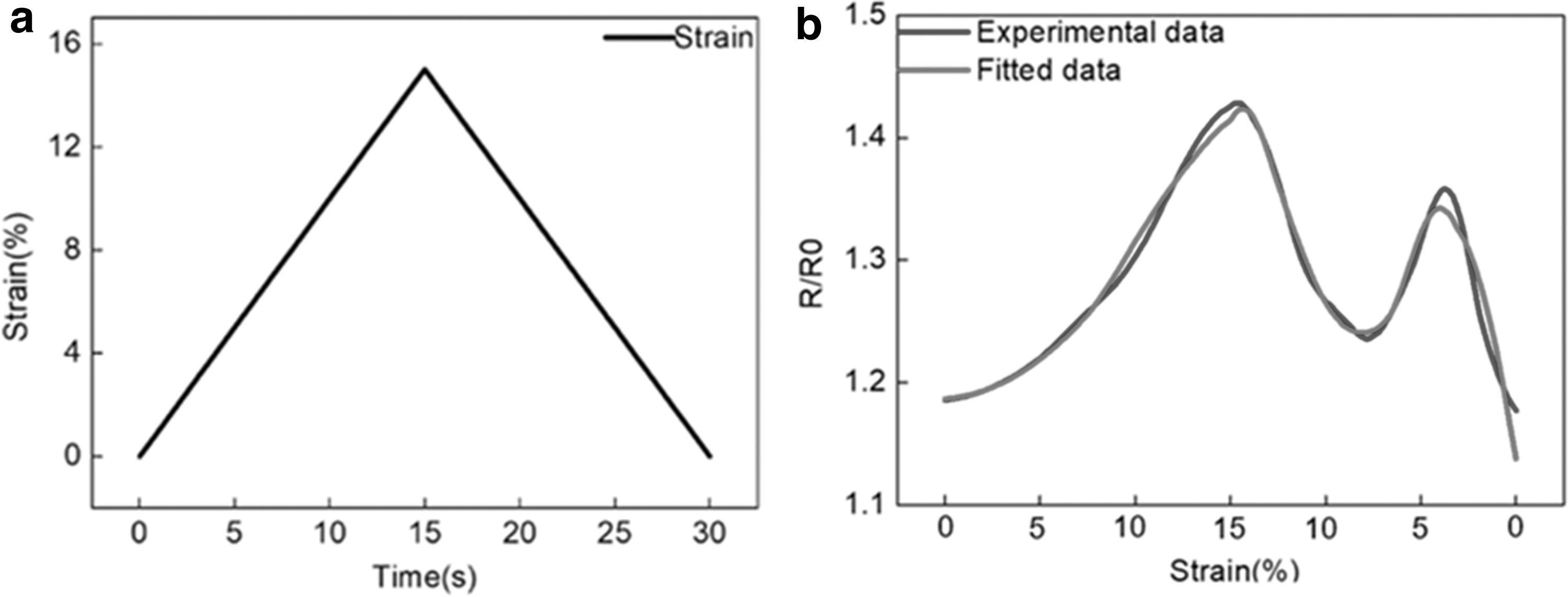
Combining the above Equations (8) and (10), we can get:

In the equation:
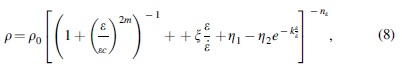
The sample is loaded with constant strain (the strain curve is shown in Fig. 6a), and the measurement results are well fitted with the theoretical model [Eq. (11)]. The fitted results are shown in Figure 6b. The corresponding fitting parameters are listed in Table 2. Due to the viscoelastic properties of the material, a shoulder peak appears to a greater extent during the unloading phase. From the curve in the figure, it is observed that the experimental value and the theoretical model have a high degree of fit in the loading and unloading stage. Therefore, the model can be used to describe the strain–resistance response of this test.
Strain resistance fitting curve.
Parameters Obtained by Fitting R/R0-Strain Curves for Multi-Walled Carbon Nanotubes/Thermoplastic Polyurethanes Composites
Potential applications of flexible sensors based on MWCNTs/TPU
Since additive manufacturing can produce complex structures, this experiment attempted to form complex-structured composite materials. The designs are shown in Figure 7a.I and a.IV, and the formed parts are shown in Figure 7a.II and a.V. This method can realize the preparation of flexible parts with complex two-dimensional and 3D structures. In this article, wearable flexible sensors were fabricated from TPU/MWCNTs composites. Human joint movements are detected by attaching sensors to different parts of the human body with the help of medical tape. Figure 7b shows the recognition of human fingers using strain sensors, which can detect the finger straightening and bending movements. Furthermore, the resistance is found to change significantly, and the resistance is recovered after the recovery action, which proves the repeatability of the sensor. Therefore, the developed sensor can be used to detect finger gestures and has significant potential in the control of gesture robots and other virtual display applications.50,51
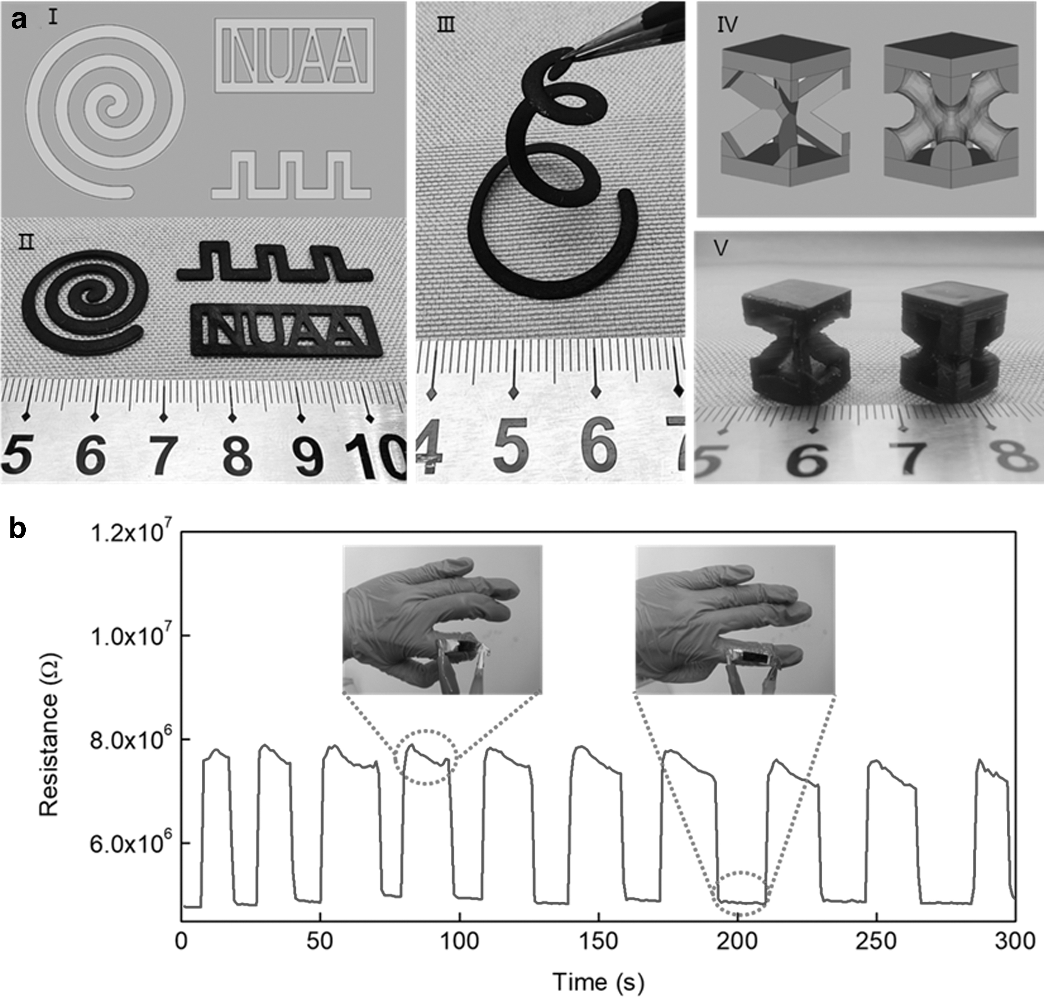
Potential applications.
Conclusions
In this work, MWCNTs were uniformly dispersed in TPU photosensitive resin using ultrasonic vibration and stirring, and low-cost flexible sensors were fabricated using self-developed DLP photocuring equipment. From the results, it was found that the prepared flexible sensor had high sensitivity and large tensile strain, with a sensitivity factor of 9.988 and a working strain range of 45%. The composites prepared in this article will fluctuate in the strain–resistance response of the material due to the competition between the destruction and reconstruction of the conductive network during stretching, thereby exhibiting a shoulder effect, and can form a stable after cyclic stretching. conductive network.
Furthermore, the fabricated strain sensor exhibited excellent cyclic stability under loading and unloading cycles, which could provide stable and repeatable electrical signals. The sensor could also reach thousands of cycles or more, demonstrating the application of strain sensors to detect the motion of human knuckles. This preparation method showed the prospect of DLP 3D printing technology in flexible sensors and provided an idea for personalized custom wearable electronic devices. Therefore, it is concluded that DLP 3D printing technology is a promising approach for wearable flexible devices, which could further promote the development of wearable electronics.
Footnotes
Acknowledgments
The authors extend their science thanks to those who contributed in instructions and experiments work.
Authors' Contributions
Author Disclosure Statement
There are no conflicts to declare.
Funding Information
This work was supported by Jiangsu Provincial Key Research and Development Program (No. BE2019002). This research was partly financed by the JITRI Institute of Precision Manufacturing.