
Abstract
Binder jetting (3DP) is a kind of additive manufacturing at room temperature and atmospheric environment, which can reduce the risk of magnesium alloy forming. Magnesium alloy powder is bonded to a certain structure by a binder, so the appropriate binder is very important in 3DP. In this study, according to the characteristics of magnesium alloy, a simple and easy-to-obtain water-based low-molecular alcohol binder was used to reduce the difficulty of magnesium alloy 3DP. Additionally, we use COMSOL Multiphysics simulation software to establish a simulation model of the movement and deposition process of the binder. The results show that the increase in jet velocity will increase the quality and saturation of droplets. More importantly, the larger the jet velocity is, the larger the spreading width of the binder droplet after impacting the powder bed, which seriously affects the dimensional accuracy of the green part. In addition, lower binder saturation will weaken the formation of interparticle bonding neck and cannot form a stable structure. Furthermore, we analyzed the bond reactants of the binder and magnesium alloy powder, which eventually decompose into MgO, and the experimental results show that the final sintered sample has considerable performance.
Highlights
A green and easily prepared binder for magnesium alloy 3DP.
Control of binder injection and deposition process by simulation software.
Jet velocity affects the dimensional accuracy and strength of the green part.
Spread width on the powder bed should be as close as possible to nozzle distance.
Introduction
Contrary to heat source-based additive manufacturing methods, 1 binder jetting (3DP) additive manufacturing is an ambient temperature-forming method, which is suitable for magnesium alloy additive manufacturing. There is no risk of oxidation and explosion at high temperatures. 2 The 3DP is a two-step manufacturing process. 3 In the first step, the binder is selectively deposited on the thin layer of the powder to make the binder interact with the powder to adhere to the particles dispersed on the powder bed. 4 This bonding process is repeated step by step until it is combined into a particular form of the green part. The second step involves post-treating of the green part printed in the first step to densify the green part after degreasing, such as sintering, 5 hot isostatic pressing, 6 etc.
Most current researches on 3DP focus on optimizing printing parameters for equipment and specific materials.7,8 Understanding the interaction between the binder and the powder will help researchers adjust the materials and related print parameters. There are physical and chemical aspects to the process of interaction between the binder and the powder. The binder was jetted from the nozzle to form microdroplets, which quickly struck the powder bed and diffused into the surface of the powder bed. 9 Then the powder layer was penetrated by the action of the capillary force, and a liquid bridge was formed between the particles, which was the prototype of the connecting neck. Printing parameters such as jet velocity and bonding saturation will affect the forming quality of 3DP. After the formation of a stable liquid bridge, the binder and the powder form a solid material, which makes the liquid bridge solidify, forming a bond neck, and connecting the particles in the powder bed into a whole. 10
On the one hand, the bonding quality is affected by the microdrop motion and the deposition process of the binder. 11 Fromm 12 initially studied the process of droplet formation by spraying the binder and defined the parameters describing the printability of this binder. Derby 13 summarized the principle of the movement of binder droplets and pointed out that the physical and rheological properties of the binder should meet certain conditions to achieve the desired bonding effect. Nefzaoui and Skurtys 14 studied the penetration process of various solution droplets and analyzed the influence of Reynolds and Weber numbers on penetration using specific experiments. Kim and Lee 15 used a high-speed camera to capture the impact process of droplets on the powder surface and analyzed the dynamic behavior of water droplets in porous media. In these investigations, high-speed cameras are generally used for observation. However, due to the limitations of the experimental conditions, the process of deposition of the binder droplets into the powder bed is not observable. 16
Numerical simulation is a good method to control the deposition of binder in the powder bed. Tan 17 offered to use direct numerical simulation to study the impact of droplets on the powder bed in microns and conducted two numerical experiments. Gao et al 18 established a capillary permeation model and analyzed the influence of various parameters on permeation results from simulation and experimentation. To study the water droplet infiltration process more intuitively, Wang et al 19 established the infiltration model and used COMSOL software to analyze the effects of contact angle, porosity, and droplet height on infiltration. However, these studies only studied one process of the droplet from ejection to penetration, without considering the interaction of the overall process.
Additionally, the strength of the green part depends on the bonding mechanism. At present, the research on the chemical mechanism of binders and powders is mostly concentrated on ceramics, stainless steel, and other materials, which can be divided into three types, including binders that cannot be bonded and reacted, binders with a bonding effect, and binders that can react with powders. 20 There are few studies on binders suitable for magnesium alloys. Salehi et al21–24 uses a solution that can interact with magnesium alloy powder to form a liquid bridge between particles under a capillary driving force and combine particles through the chemical action of the solution with magnesium alloy particles. This solution needs special preparation and is not easy to obtain, which is not conducive to the popularization of additive production in magnesium alloy. Su et al 25 used a water-based low-molecular alcohol binder to bind magnesium alloy powder, but did not study the bonding mechanism and did not analyze the chemical process.
Therefore, due to the chemical properties of magnesium alloy, a water-based low-molecular alcohol binder that may react with magnesium alloy powder has been developed in this document. This binder is usually easily obtainable and its cost is low. Its main components are water and glycerol, where water is used as a reactive bonding agent, and glycerol is used as a thickener for viscosity adjustment. To study the action of this binder and magnesium alloy powder, we used numerical simulation to establish the model of the binder jetting and deposition process, obtained the influence law of binder saturation and jet velocity, and summarized the relationship between jet velocity and dimensional accuracy throughout the process of binder jetting. Combined with scanning electron microscopy and vibration spectroscopy, the bonding mechanism between the binder and magnesium alloy powder was analyzed, and the formation effect of the bonding neck between magnesium alloy particles was predicted.
Experimental Design and Methods
Waiver statement
Now the study is in the process research stage, and it has not been applied to clinical treatment. Therefore, all experiments in this paper do not involve human or animal subjects, and this behavior also do not violate ethics.
Materials
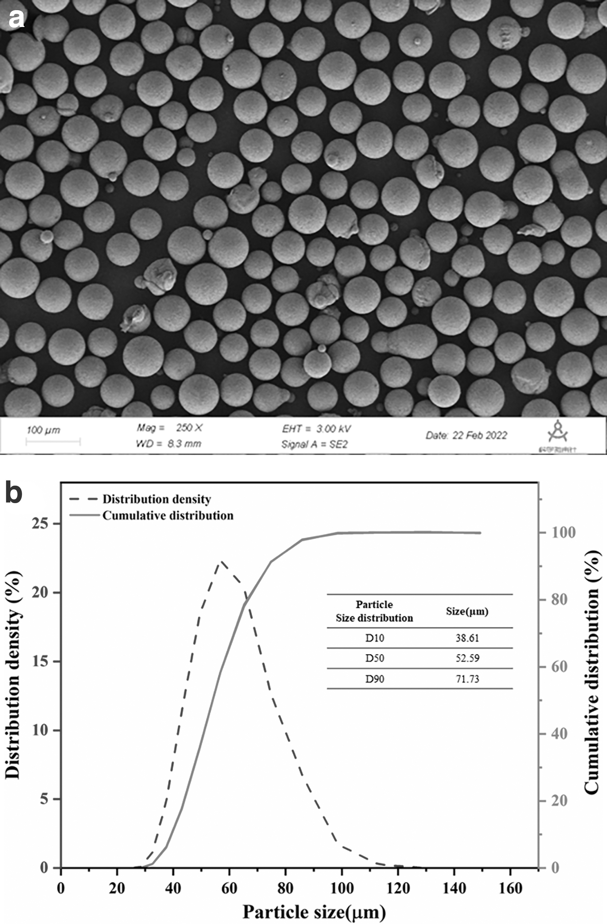
AZ91D magnesium alloy with Mg-9.08 wt%Al-0.65 wt%Zn chemical composition was used as raw powder material. As shown in Figure 1a, the powder particles are highly spherical. The particle size distribution of the powder is illustrated in Figure 1b, with the D50 of 52.91 μm. The other measured characteristics of powder include pycnometer density of 1.82 g/cm−3, the apparent density of 0.944 g/cm−3, and relative density of 51.87%.
AZ91D powder characteristics
3D printing process
Piezoelectric jetting on demand is used in 3DP. The device primarily drives the metal film to generate a pressure pulse by the vibration of the piezoelectric plate, and the extrusion gun sprays binder. The experimental instrument is a P110 device from the Wuhan 3DPAction company. The height of the nozzle from the powder bed in the experimental equipment is 1.5 mm. The printing nozzle of the equipment is a Starlight piezoelectric nozzle with the DPI of 400 and the nozzle spacing of 63.5 μm. In other words, there are 400 droplets in an inch.
In the experiment, we printed a specific pattern on the article and only one droplet will fall in the same position on each pixel. We weighed the increased quality
where S is the area of the printed pattern and
Figure 2 shows the complete flow of the 3DP process for producing the green part. The powder is filled into the powder supply bed of the 3DP printer, and the rotating roller spreads a thin layer of powder from the supply cylinder to the build cylinder. The printing nozzle deposits the binder on the specified surface of the 100 μm thick powder layer (Fig. 2b). Under the capillary force, the bonding agent forms a liquid bridge between the powder layer particles. Due to the gradual interaction between powder particles and binders, this liquid bridge transforms into a strong binding neck. The next layer is stacked onto the previous layer (Fig. 2a) and circulates the above process into a whole. Eventually, we print out green parts of 10 × 10 × 15 mm.

After drying, the green part was degreased at 400°C for 2 h. Then the samples were sintered by a two-step method under argon protection. The parts were heated to 620°C at a heating rate of 10°C/min for 0.5 h. Then they were rapidly cooled to 580°C for 12 h and then cooled to room temperature with the furnace.
Characterization methods
The density of the raw materials was obtained through the HYL-101 mass tester, and the particle size distribution of the powder was obtained through the Malvern Mastersizer 2000 laser particle size analyzer. The ZEISS Gemini 300 (FESEM) scanning electron microscope was used for the detection of bonding neck between particles. The energy dispersive spectroscopy analysis was performed to show the distribution of the elements. The WDW-100 material test machine was used to perform the compression test of sintered samples at a constant deformation rate of 0.1 mm/min. Image software was used to measure the density after sintering from the optical image of the polished cross-section. Using Renishaw's in Via Raman spectrometer and 514 mm wavelength, the samples were qualitatively analyzed in the wavenumber range of 50–4000 cm−1.
Qualitative analysis was carried out on the green part with Thermo Scientific Nicolet iS20 Fourier-transform infrared spectrometer. First of all, in a dry environment, a small number of samples and an appropriate quantity of dry potassium bromide powder, which were used to dilute the sample to avoid absorption saturation, were added to the mortar and completely pressed for many times. Afterward, the samples were pressed onto a shelf, and the infrared spectra of the samples were taken from 400 to 4000 cm−1.
Simulation Model of Binder Jetting and Penetration
Due to the limitation of process visualization, this article describes the jetting and deposition of binder jetting by COMSOL Multiphysics simulation software. After droplets of the binder are jetted from the nozzle, it hits the powder bed and then permeate. This entire process is complicated. Jetting and deposition process affect the effect of powder bonding. Therefore, it is especially important to analyze the movement process of the binder to better optimize its bonding with powder.
Simulation modeling of binder droplet motion
The two-phase flow and level set module in COMSOL Multiphysics software is selected, and the control equation is the Navier–Stokes equation. The Navier–Stokes equation is the basic mechanical equation for describing the movement of the liquid, which can well describe the flux of binder in the pores of powder bed particles. The NS equation is expressed as follows.
where
The level set method is applied to describe the change of the binder after it is ejected and the change of the flow–diffusion interface in the powder bed. It perceives the fluid interface with time as a zero-level set of certain
where u is the fluid velocity;
Establishment of powder bed
The two-dimensional model of the powder bed is established by COMSOL Multiphysics simulation software.
We assume that there are two independent standard normal distributions X ∼ N (0,1) and Y ∼ N (0,1). Since they are independent of each other, the joint probability density function is:
The Eq. (4) can be transformed by polar coordinate.
The above results can be seen as the product of the density functions of two probability distributions, one of which can be seen as a uniform distribution on [0,2π]. Converting it to a standard uniform distribution, there is:
Where V is an independent variable obeying uniform distribution. The other density function is:
The cumulative distribution function (CDF) is:
The inverse function of this CDF function can be written as:
According to the principle of inverse transform sampling, if we have a probability density function of P(R), then the sample distribution obtained by uniformly sampling the inverse function of the aligned CDF will conform to the distribution of P(R). If u is uniformly distributed, then
Two random numbers U and V are obtained by a random function. Then the two random numbers are substituted into the Box–Buller algorithm (Eqs. 10 and 11) to obtain the normal distribution of the particle radius X, and the position of the particles is randomly set.
Size and position are randomly generated during the creation of particles, which can cause overlap of particles. Therefore, the contact detection of particles is very necessary. To reduce the detection time, we use the following methods. The center position of particle A in the model space is (x1, y1, z1), and the radius is R1. The particle B has a center position of (x2, y2, z2) and a radius of R2. So, the distance
Each time a new particle is created, the minimum center distance from the created particle is calculated. The minimum distance is:
If the minimum distance
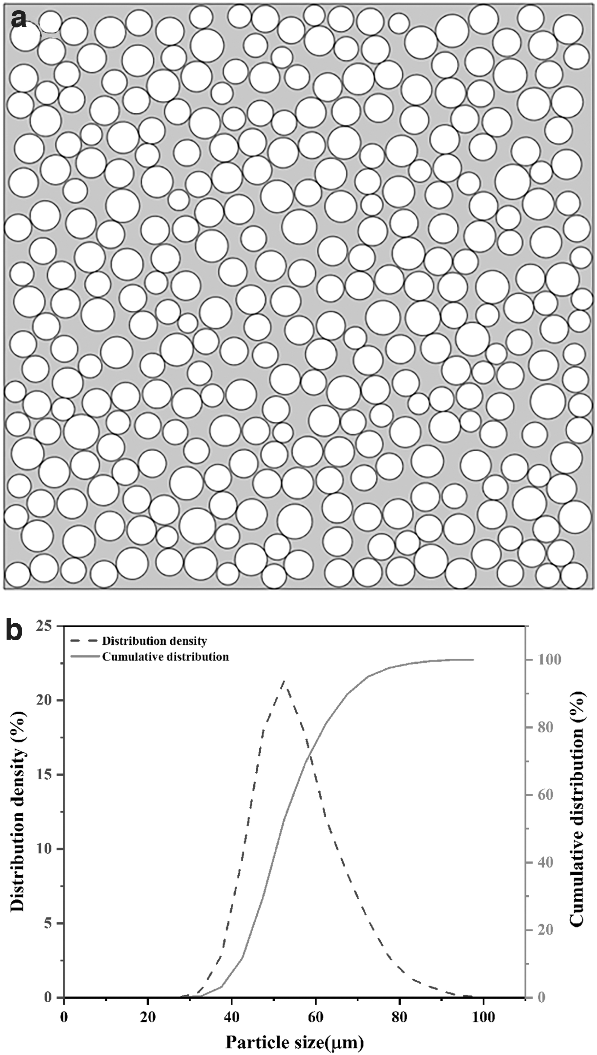
The random particle distribution model (Fig. 3a, b) is constructed in such a way, the particle distribution in the powder layer model is approximate to the actual distribution (Fig. 1a, b).
(
Boundary condition
To reduce the difficulty of model establishment, it is assumed that the adsorption and desorption of particles are ignored when the binder flows in the gap of powder particles. The material is isotropic, and the local permeability satisfies the capillary model. The binder is a water-based, low-molecular alcohol solution with physical properties indicated in Table 1. The binder is assumed to be an incompressible Newtonian fluid, with a laminar flow. The capillary pressure pushes the binder down into the powder, ignoring the effect of gravity.
Physical Properties of the Binder
The nozzle size and the distance from the powder bed are consistent with the actual equipment in the model. The inlet is set to the pressure required for binder ejection. The condition of the outlet pressure envelope is set to zero relative pressure. The surface of the particles in the powder bed is a dampening wall at a contact angle of 27.2°. The ink cavity and nozzle area are set as binders, and the remaining area is air (Fig. 4).

Simulation model and its meshing.
Mesh
The final simulation model and its meshing are shown in Figure 4. The mesh is a free triangular unit, with a maximum unit size of 8.04 μm and a minimum unit size of 0.024 μm.
Results and Discussion
Jet and drop
We calculated the mass of droplets at different jet velocities in the simulation model, which was consistent with the experimental data by measuring the quality of jetting on article. As the jet velocity increases from 5 to 10 m/s, the viscous force inside the liquid column increases gradually. To overcome the drag of viscous force, the head of the liquid column must have higher kinetic energy to break into droplets. 26 Therefore, the droplet mass increases with the increase of velocity. However, when the binder is jetted at a high velocity, too many satellite droplets will be produced (Fig. 6e, f), so the simulation results deviate greatly from the experimental data.
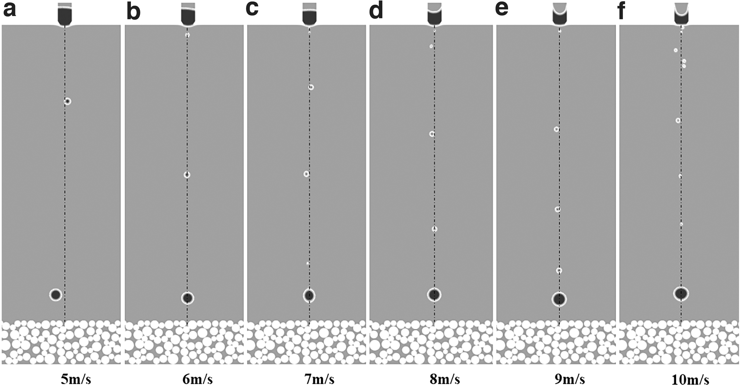
The droplet motion state under different jet velocities.
More importantly, with the increase of jet velocity, the saturation of the binder gradually increases from 27% to 55% (Fig. 5), which is the ratio of the volume of the binder to the total pore volume in the particle (Eq. 14).
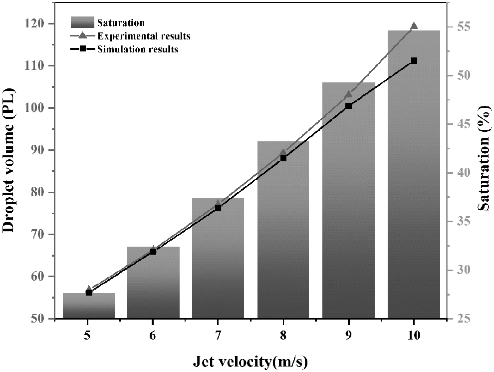
The droplet mass of binder obtained by experiment and that obtained by simulation.
When printing each layer, the volume of pores between powders that each nozzle is responsible for filling can be expressed by nozzle spacing and density. Saturation S can also be calculated by Eq. (15), where
In addition, the simulation shows that when the jet velocity of binder is 5 m/s, the droplet does not have enough kinetic energy to overcome the airflow resistance (Fig. 6a), deviates from its linear trajectory, and affects the accurate deposition of the droplet. The jet velocity of the binder must be >5 m/s.
Physical bonding between binder and magnesium alloy powder
The physical interaction between binder droplets and powder particles includes the impact of droplets on the powder and the penetration and flow of binder between particles. 27 These processes are driven by inertial, capillary, and gravitational forces. These rapidly jetted binder droplets with a diameter of 20–80 μm have high kinetic energy. They are rapidly spread on the surface of the powder layer and deposited into the powder bed after impacting the powder bed (Fig. 2b). Then, the liquid bridge connecting particles is formed by the permeation of binder in pores between particles under capillary force. The liquid film attached to the particle surface moves slowly toward the liquid bridge, making the liquid bridge grow.
The spreading width of droplets on the powder bed depends on Reynolds number Re. The larger the jet velocity is, the larger the Reynolds coefficient; the stronger the diffusion ability is, the larger the spreading radius. When the jet velocity is 5 m/s, the droplet deviates from the vertical falling trajectory (Fig. 7a). The simulation shows that when the droplet hits the powder bed, due to the obstruction of the powder bed, the lateral spreading rate of the binder is much larger than the longitudinal penetration rate. Therefore, the binder is distributed in an inverted triangle in the powder bed (Fig. 7). With the increase in jet velocity, the spreading radius of the droplet impacting the powder bed increases from 68 to 155 μm (Fig. 8).

Binder droplets at different jet velocities spread over a powder bed.

Spread radius and impact depth of droplet in simulation.
The penetration profile of a single droplet can be represented by a triangular contour in the figure (Fig. 9). The bottom edge represents the diffusion width and the height represents the penetration depth. When the spreading radius R is less than the nozzle distance L, each droplet only partially fuses, and the uniformity of binder on the powder thin layer is poor (Fig. 9a). When the spreading radius is equal to the nozzle spacing, the best uniformity can be obtained (Fig. 9b). According to the dots per inch calculation of the print nozzle, the nozzle distance is 63.5 μm, and the jet velocities with close spreading radius should be selected, such as 8 and 9 m/s.

Spreading and fusion of microdroplets on the powder bed.
We measured the size of the actually printed sample in the experiment (Fig. 10), which is similar to the simulation results. When the jet velocities are ≤7 m/s, the overall size is less than the specified size due to the uneven combination between the various binder droplets. When the jet velocity is 8 m/s, the error with the specified size is the smallest. With the increase of jet velocity, the saturation of the binder increases, so when the jet velocity is >9 m/s, the sample size is greater than the specified size. In addition, driven by capillary force, the binder gradually penetrates the powder bed. Due to the layer-by-layer accumulation of binder, the bottom size is slightly larger than the top size, and the height size is always greater than the specified size, so the sample is conical. But the effect of jet velocity on vertical dimension is small. The aforementioned phenomena will affect dimensional accuracy, but can be effectively improved by modifying the printing process.

The size of green part at the jet velocity of 6, 7, 8, 9, and 10 m/s.
The binding force of the binder between particles is generated by the surface tension and capillary force of the binder, so the volume of the binder has a great influence on the green part. When the jet velocity is <6 m/s, the S < 30% (Fig. 5) and the filling amount of the binder in the gap between the particles is very small. The liquid connects the particles with a dispersed liquid bridge in a ribbon shape. Some particles cannot form a bond neck due to the lack of binder (Fig. 11a). When the jet velocity is <9 m/s, the binder in the particle exists in the form of a pendulum, the liquid forms a continuous phase and the void becomes smaller (Fig. 11b–f), so the particles can be stably bonded. When the jet velocity is >9 m/s, S > 50% (Fig. 5). It increases to fill the internal voids of the particles so that the particles are suspended in the binder (Fig. 11f), and the particles are loose. At this time, the strength of the green part increases with the increase of the jet velocity (Fig. 12). The green parts must have strong strength to maintain a stable structure.
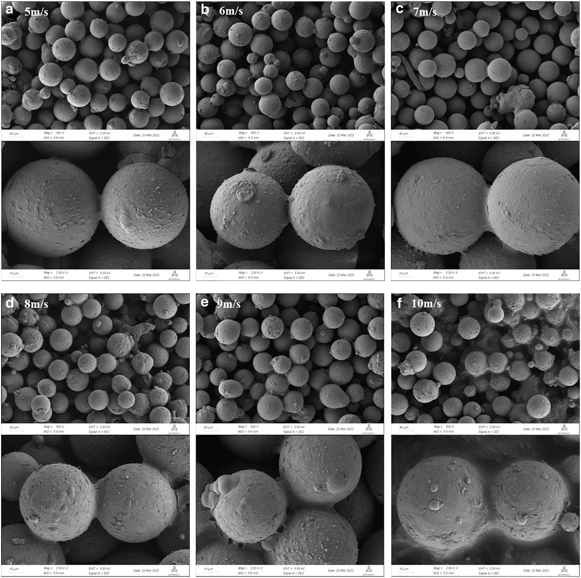
Bonding of binder in magnesium alloy powder at different jet velocities.
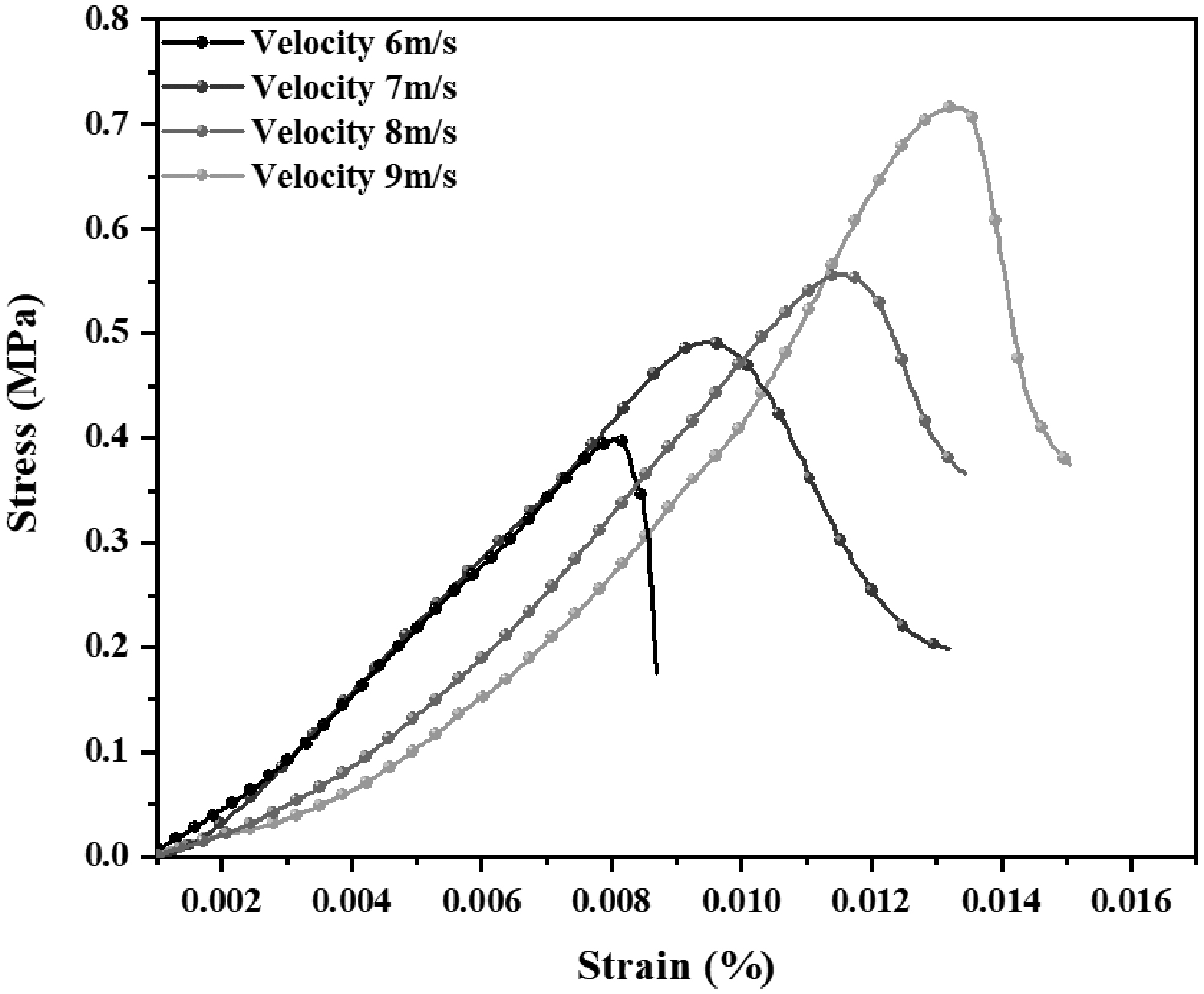
The green part strength at the jet velocity of 6, 7, 8, 9 m/s.
Chemical bonding between binder and magnesium alloy powder
The solid material Mg(OH)2 is produced by the reaction between water and Mg after the binder network between particles remains stable (Eq. 16). These solids connect the two particles to form a bonding neck (Fig. 15a). Of course, due to the flow of binders on the particle surface, these compounds may also be formed on the particle surface far from the liquid bridge. The particle surface will form point substances (Fig. 13b), which are attached to the surface of the MgO film. At the same time, these liquids will also be continually transferred to the adjacent bonding neck, so that the bonding neck will continue to grow. The permeability and transfer process in the pores of the binder is very slow, which normally takes 0.1–1 s. The bonding neck between the particles makes the thin layer have some strength, and the following powder layer can be spread over the pre-pre-ad layer without displacement. After the binder is deposited into the new layer, bonding necks are formed between the layers and the particles in the layer, and the layer is connected to the layer (Fig. 2b). These steps of binder deposition and powder spraying are repeated until the printing of the whole object is completed.

SEM pictures of bonding neck and distribution of Mg, O, and C elements on bonding neck.
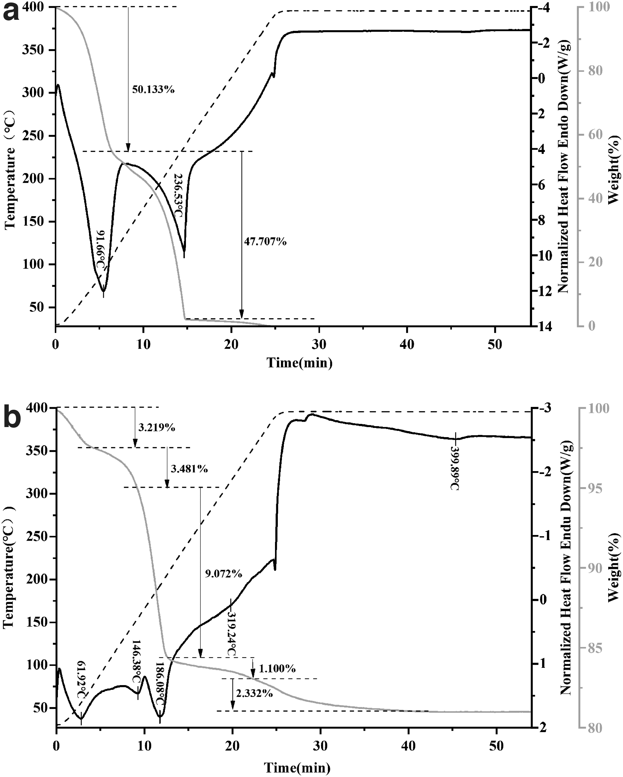
TGA and DTA curves of
After printing, the powder bed was put into the drying box to fully solidify the bonding neck, wherein Mg(OH)2 was combined with carbon dioxide in the air to form magnesium bicarbonate (Eq. 17). The formed Mg(OH)2 reacted with residual water at 90°C to form MgCO3·3H2O (Eq. 18). After holding for a while, the stable green part can be removed from the surrounding loose powder. The Mg element in the particulates was transferred to the bonding neck because the Mg compound was formed after the reaction with the binder (Fig. 13d). The C and O elements of the bonding neck can be derived from binders or magnesium compounds. The C element on the particle surface confirmed that the binder would adhere to the particle surface during infiltration (Fig. 13e). The dense O element reflects the oxidative power of magnesium (Fig. 13f).
We conducted infrared spectroscopy (Fig. 14a) and analysis of Raman spectroscopy materials (Fig. 14b) to determine the composition of the initial billet and to facilitate postprocessing program planning. The wide absorption peak at about 3410 cm−1 may be caused by the sample itself containing water or absorbing water in the air, which belongs to the stretching vibration peak of −OH in water molecules or magnesium hydroxide.28–31 The absorption peak of the sample at 2880 cm−1 was attributed to the symmetric stretching vibration peak of methyl-CH3.32,33 The stretching, vibration peak of C = C appeared at about 1620 cm−1 and the stretching vibration peak of C-O appeared at 1100 and 1050 cm−1, which may be from the butyl ether in the material. The absorption peaks at about 1440 and 860 cm−1 were attributed to the antisymmetric stretching, and vibration peak of carbonate CO32−, which was caused by magnesium carbonate trihydrate in the material. The infrared absorption peaks at about 725 and 576 cm−1 belong to the stretching vibration peak of Mg-O. 34

Raman spectroscopy is a spectroscopic technique used to study the vibration mode, rotation mode, and other low-frequency modes of lattices and molecules in a system. It can be seen from the figure that the peak at 250 cm−1 is attributed to Mg(OH)2,35,36 and the absorption peaks at 373 and 541 cm−1 are caused by MgO. The Raman absorption peak at 1078 cm−1 is attributed to the CO32− vibration peak of carbonate,37,38 and the absorption peak at 2865 cm−1 is attributed to the stretching vibration peak of C-H in methyl. The Raman peaks at 3568 and 3648 cm−1 belong to the stretching vibration peak of -OH.
Postprocessing of green part
The organic components in the binder need to be removed in the vacuum degreasing furnace, in which glycerol volatilizes at about 130 ∼ 240°C (Fig. 15a), and impurities such as residual colorants will be removed later. The evaporated glycerol does not contaminate the sample because the pyrolysis products are acetaldehyde, acrolein, and carbon monoxide. These gaseous substances will be carried away by flowing inert gases. 39 During the degreasing process, all the solvent–powder interaction products can be completely decomposed without leaving impurities. The MgCO3·3H2O was carried out by a three-step dehydration reaction and one-step decarburization of anhydrous magnesium carbonate. The three-step dehydration reactions occurred at 55–109°C, 109–160°C, and 160–270°C. 22 The adsorbed water will be simultaneously dehydrated in the first two steps of magnesium carbonate trihydrate. In the third step of dehydration, the mass change is more obvious because of the volatilization of glycerol in the binder.
The remaining CO2 begins to decompose and volatilize at 330°C (Fig. 15b). After heating, Mg(OH)2 began to decompose into MgO at 210°C (Fig. 15b). The MgO structure generated by these decompositions will form an overall structure with the original oxide film of particles, which is conducive to maintaining the shape in sintering and reducing the shrinkage rate.
We used a two-step sintering method, rapid heating to 620°C after holding for some time, the billet produced a part of the liquid phase, so that it can break the outer oxide film and fill the pores. Then it cools to 580°C to keep the initial shape. The compressive strength of sintered samples can increase to 169 MPa (Fig. 16a) and the elastic ink is 34.79 GPa. The porosity measured by Image is 69.64% (Fig. 16b). Compared with the magnesium alloy parts formed without binder, the properties of the samples fabricated by 3DP in this article are significantly higher than those of the parts sintered at 577°C for 40 h and are equivalent to those of the parts sintered at the same temperature for 60 h (Table 2). It is better that we reduce a lot of sintering time. The above data show that the binder is appropriate for the 3DP magnesium alloy. It is inexpensive and easy to get are obvious advantages, which reduce the difficulty and cost of 3DP magnesium alloy.

Physical and Mechanical Properties of Samples for Various Sintering Processes
UCS, ultimate compressive strength.
Conclusion
In this article, the simulation model of binder jetting and deposition in 3DP was established, and the bonding mechanism between magnesium alloy powder and water-based binder was analyzed. The following conclusions were drawn:
① The change of ejection velocity in the printing process affects the quality of droplets, resulting in different binder saturations. As the jet velocity is from 5 to 10 m/s, the quality of the droplets increases. The saturation of the binder thus increases from 27% to 54%. ② Jetting velocity determines the spreading radius of the droplet in the powder bed. The larger the jetting velocity is, the larger the spreading radius. The distribution of binder in powder bed is an inverted triangle. When the spreading radius of droplet impacting the powder bed is equal to the nozzle distance, the binder is evenly distributed and the dimensional accuracy is high. ③ The saturation of binder affects the formation of interparticle bond neck. When the binder saturation is <30%, the local particles do not bond into a whole, and the initial strength is poor. When the binder saturation is >50%, the bonding neck between particles will form a whole, but the size accuracy of the green part is poor. ④ The binder we used in magnesium alloy 3DP forming is generally available and low cost in the market, and significantly reduces the development cost. The binder binds the particles firmly into a whole by reacting with the solid material produced by the magnesium alloy powder. These reactants can be decomposed into MgO during degreasing. Considerable performance is obtained with this binder.
In the future, this binder can be applied to the 3DP additive manufacturing of other materials to better promote the development and maturity of 3DP technology.
Footnotes
Authors' Contributions
Q.Y.: writing—original draft, and methodology. M.L.: software. Z.Z.: investigation. X.L.: software. J.L.: writing—reviewing and editing.
Author Disclosure Statement
No competing financial interests exist.
Funding Information
The study received support from the National Natural Science Foundation of China (51775069) and Natural Science Foundation of Chongqing (cstc2019jcyj-msxmX0362).