
Abstract
A novel shear test method on shear bond behavior of 3D printed interlayer interfaces and interstrip interfaces was proposed in this study. Thereafter, the effect of different replacement ratios of recycled sand, printing intervals, and surface treatments were investigated. The test results showed that under the same printing condition, the interfacial shear strengths of interlayer interface and interstrip interface were similar to each other. The interfacial shear strength slightly decreased with the increase of the replacement ratio of recycled sand, while it sharply decreased with the extension of printing interval time. The interfaces in 3D printed recycled mortar had higher time sensitivity compared with 3D printed natural mortar. Considering that discontinuous construction will introduce inferior interfaces in 3D printed concrete components, effective surface treatments should be conducted. According to the test results, the improvement effect of surface treatments was epoxy paste > cement paste > surface wetting > no treatment.
Introduction
In recent years, extrusion-based 3D printing concrete (3DPC) technology has been successfully applied in building construction. It has been widely concerned for its advantages such as less labor consumption, low pollution, formwork-free construction, and the convenience for individual design.1–6
The extrusion-based printing process inevitably introduces large quantities of interfaces in 3DPC materials and structures. Some mechanical and microscopic studies for 3DPC have shown that the properties of these interfaces are obviously lower than printed filaments. 7 Anisotropy is one of the most significant characteristics of 3DPC, compared with conventional cast concrete, 8 which is relevant to the quantities, distributions, and properties of these printed interfaces. Thus, the interface properties are essential to the extrusion-based 3DPC structure, which should be paid close attention to. Paul et al. 9 found that the compressive and flexural behaviors were closely related to printed direction, which were also proven by the authors' previous work. 10 Wolfs et al. 11 conducted the flexural and splitting test of 3DPC and cast specimens, showing that cracks tend to propagate along the inferior interfaces between filaments in 3DPC specimens.
The bending capacity of 3DPC specimens was lower compared with cast specimens. Zhu et al. 12 studied the mechanical properties of 3D printed engineered cementitious composite beams with different printed angles; when mid-span bending cracks developed along the printed interfaces, the bearing capacity and ductility decreased obviously. Pham et al. 13 also confirmed that interface orientation had a significant influence on the bending resistance of 3DPC specimens. In addition, microscopic studies found that due to the extrusion process and lack of vibration, there were large quantities of pores at the 3D printed interface areas. Some microchannels were connected to form a unique interconnected pore network at interface areas. The porosity in 3DPC preferentially aligned with the printing direction and was highly heterogeneously distributed. The largest pores in the 3DPC specimens were found to be larger than those in the cast specimens. 14 Triaxial spheroid-shaped pores, elongated and flattened in print direction, were found in printed specimens by Kruger et al., 15 whereas the spherical pores with a random distribution were observed in cast specimens.
Van den Heever et al. 16 assumed the elongated and flattened pores in 3DPC to be the ellipsoids and then theoretically analyzed the mechanical response of stress concentration at pore boundary under different conditions. The pores along the interlayer interface may lead to more adverse stress concentrations.
The factors affecting the bond behavior of 3DPC interface can be divided into direct factors and indirect factors. The direct factors are the essential factors influencing the formation of the interface, such as the pore structure, 16 rheological properties of printing material, 17 the effective bonding area, 18 hydration process, etc. However, the indirect factors can be adjusted manually to optimize the interface performance, such as material mixtures, surface treatments, printing parameters, environmental conditions, etc. The influence mechanisms of the abovementioned factors have been studied by many scholars in recent years through experimental study, theoretical analysis, microscopic scanning, and fluid mechanics simulation.8–21
The material proportions, on one hand, change the rheological properties of mortar, physically influencing the intercontact of printed filaments. On the other hand, the initial water content, water secretion, and even chemical composition are adjusted to chemically optimize the hydration process and hydration products.19–24 Different kinds of admixtures and fibers can also improve the water loss and cracking problems of 3DPC. The surface treatments mainly refer to additional surface agents and moisture. The cement-based surface agents can reduce the pores and increase the effective bond area, while the epoxy-based agents and various types of modified mortar can generate much stronger hydration products in the interface area.25–29 The printing parameters, such as printing interval time, printing speed, printing path, and printing height, influence the flowability of printed filaments and also the extrusion and compression effect between filaments. The interface distribution and direction were closely related to the printing path.30–34
The environmental conditions predominantly mean temperature and humidity in the process of printing and curing. The appropriate temperature and relatively higher humidity will promote the hydration process, then improve interfacial properties.35,36
As for the experimental studies of 3DPC interfacial properties, splitting tests, flexural tests, and oblique shear tests, as shown in Figure 1, were used to indirectly characterize the interfacial bond behavior, 37 which cannot avoid the influence of bidirectional stress coupling and multi-interface interactions in 3DPC.
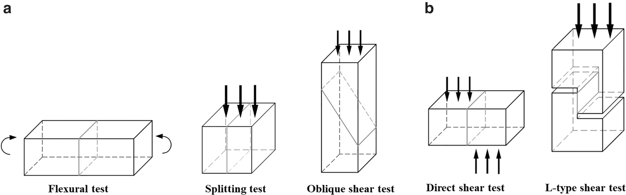
Test methods for interface properties.
Direct shear test is one of the most common direct test methods of interfacial shear strength.38,39 However, the difficulty of parallel loading, large dispersion of the results, and obvious bending effect limit its application. 40 Whereas, L-type shear test is the modified testing method of direct shear test. L-type shear test was first proposed by Hofbeck et al., 41 and then was widely used in the interface test of cast concrete, such as composite concrete and new-to-old concrete. With the advantage of its shape, the tested specimens approximately under the pure shear stress state, and the influence of stress concentration at the boundary can be reduced. However, the L-type shear test has not been modified to be used for testing 3DPC interfacial shear strength yet.
In addition, the recycled aggregate is produced by crushing and sieving of the construction and deconstruction (C&D) waste. It can reduce the landfill of C&D waste and alleviate the shortage of natural aggregates, which is proved as an effective way of sustainable utilization of C&D waste. The recycled coarse aggregate with the particle size larger than 4.75 mm has been widely studied. However, application of recycled sand with smaller particle size remains a challenge because of its remarkably high water absorption. Previous studies found that recycled mortar has the properties of fast hardening and higher early strength, which can reduce the lateral deformation of printed filaments, and improve the buildability for 3DPC.42,43 The properties of interfaces in 3DPC may be influenced by the application of recycled sand. On one hand, the high water absorption of recycled sand affects the flow state of printed mortar. One the other hand, the recycled sand contains more microcracks and more connected pores than natural sand, 44 which may provide extra channels for water transmission.
However, recent studies have focused more on the printability and basic mechanical properties of 3D printed mortar. The researches on interface bond properties of 3D printing recycled concrete are insufficient, especially the influence mechanism of the application of recycled sand on interface bond properties.
Against the abovementioned problems, a modified L-type shear test method of 3D printed interfaces was proposed in this study to evaluate the influence mechanism of recycled sand on the interfacial bond properties. The effects of different printing intervals and surface treatments were also investigated, to provide some reference for 3DPC construction.
Experimental Program
Material
Ordinary Portland cement (P.O 42.5), tap water, natural sand, and recycled sand with particle sizes below 1.18 mm; admixtures, including sodium gluconate, nanoclay, hydroxypropyl methyl cellulose, and polycarboxylate superplasticizer, were selected in this study. The recycled sand was produced from the waste concrete by a local C&D waste recycling plant in Shanghai, China. The water absorption of natural and recycled sand was about 4% and 14%, respectively.
The mixture of recycled mortar is listed in Table 1. The cement–sand ratio and water–cement ratio were 1.0 and 0.35, respectively. The additional water was calculated according to water absorption of recycled sand. The recycled mortar can be extruded continuously and uniformly, which meets the printability requirements. In addition, cement paste and epoxy paste were used as interface agents. The water–cement ratio of cement paste was the same as the printing mortar. The epoxy mortar was composed of epoxy resin A, hardener liquid B, and quartz sand, mixed at 1:1:10 by weight. Epoxy resin A and hardener liquid B were first mixed together, then mixed with quartz sand before using.
Mix of 3D Printed Mortar (by Weight)
The number after R indicates the replacement ratio of recycled sand.
HPMC, hydroxypropyl methyl cellulose; OPC, ordinary Portland cement.
Three 70.7 × 70.7 × 70.7 mm cubes of each mix proportion were cast for compressive strength test, as shown in Table 2. When the replacement ratio of recycled sand increased from 0% to 100%, the strength decreased by about 30%.
Cube Compressive Strength of 3D Printed Mortar
Specimen design
The interfaces of 3D printed concrete can be divided into two different types, namely interlayer interface and interstrip interface, as displayed in Figure 2. “Interlayer interface” refers to the interface perpendicular to the deposition direction, which is located between layers. “Interstrip interface” refers to the interface perpendicular to the translation direction, which is located between printed filaments. In general, the interlayer interface is mostly affected by gravity of upper printing filaments, while the interstrip interface is mostly affected by lateral deformation of printing filaments. The two types of interfaces should be studied individually, because of the different pore characteristics.15,16
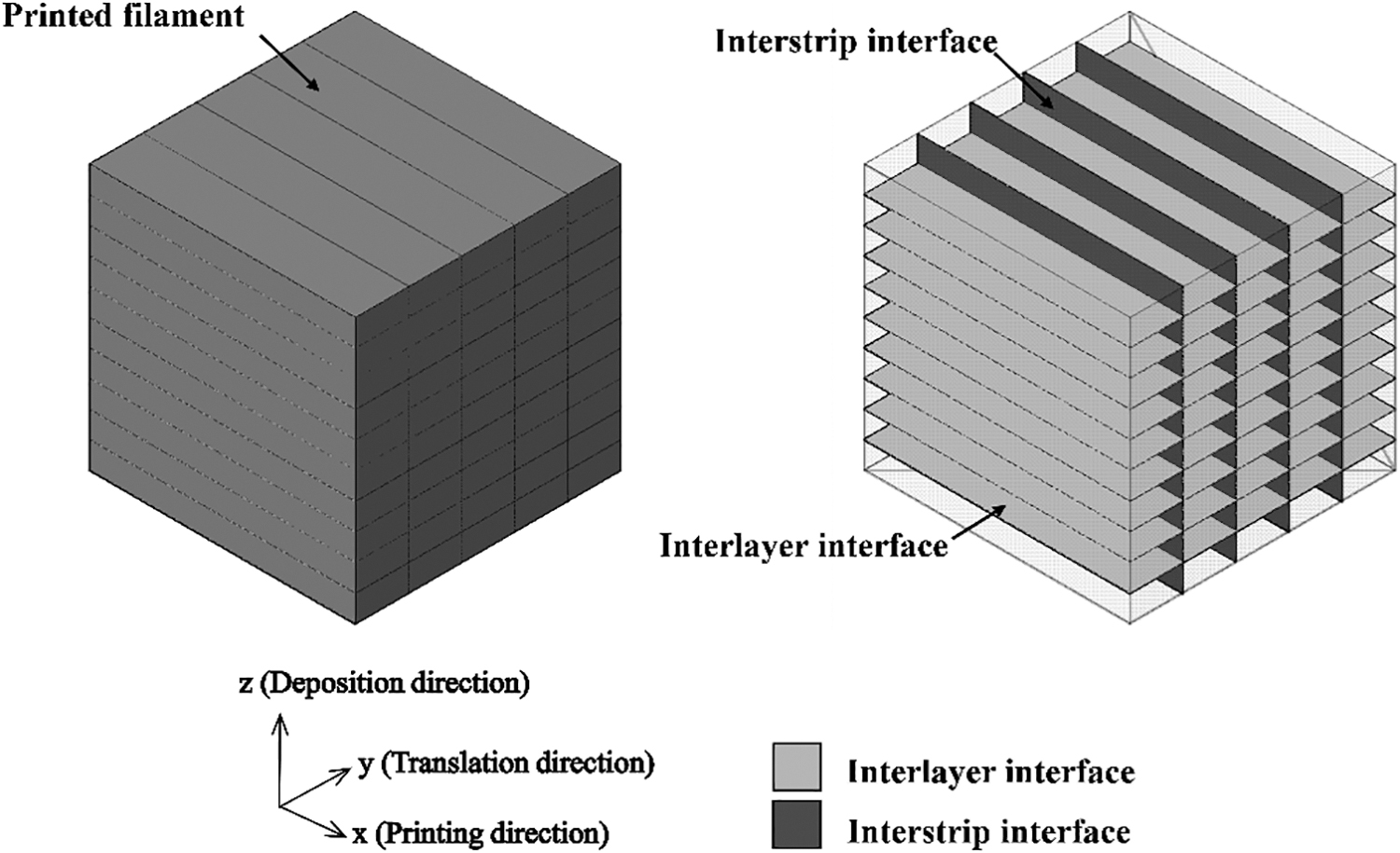
Schematic diagram of 3D printed concrete interfaces.
The optimized L-shaped specimen was adopted to study the pure shear stress behavior of tested interface. The overall size of the specimen was 100 × 100 × 200 mm, and the height of the tested interface was 50 mm. Different from the traditional L-shaped specimen for cast specimens (Fig. 3a), several inferior printed nontested interfaces were also contained in the 3D printed specimens. Therefore, two steel bars were inserted to avoid the sudden failure of those nontested interfaces, as shown in Figure 3b. The influence of two steel bars was negligible since they did not pass through the tested interface, which can be verified by a simple finite element analysis. The finite element models of L-shaped shear specimens with or without steel bars, respectively, were established by the software ABAQUS. Solid element (C3D8R) was used to simulate both steel bar and concrete. Tie constraints were set between steel bars and concrete. The boundary conditions were set as the same as the test. The shear stress of the tested interface is shown in Figure 4.
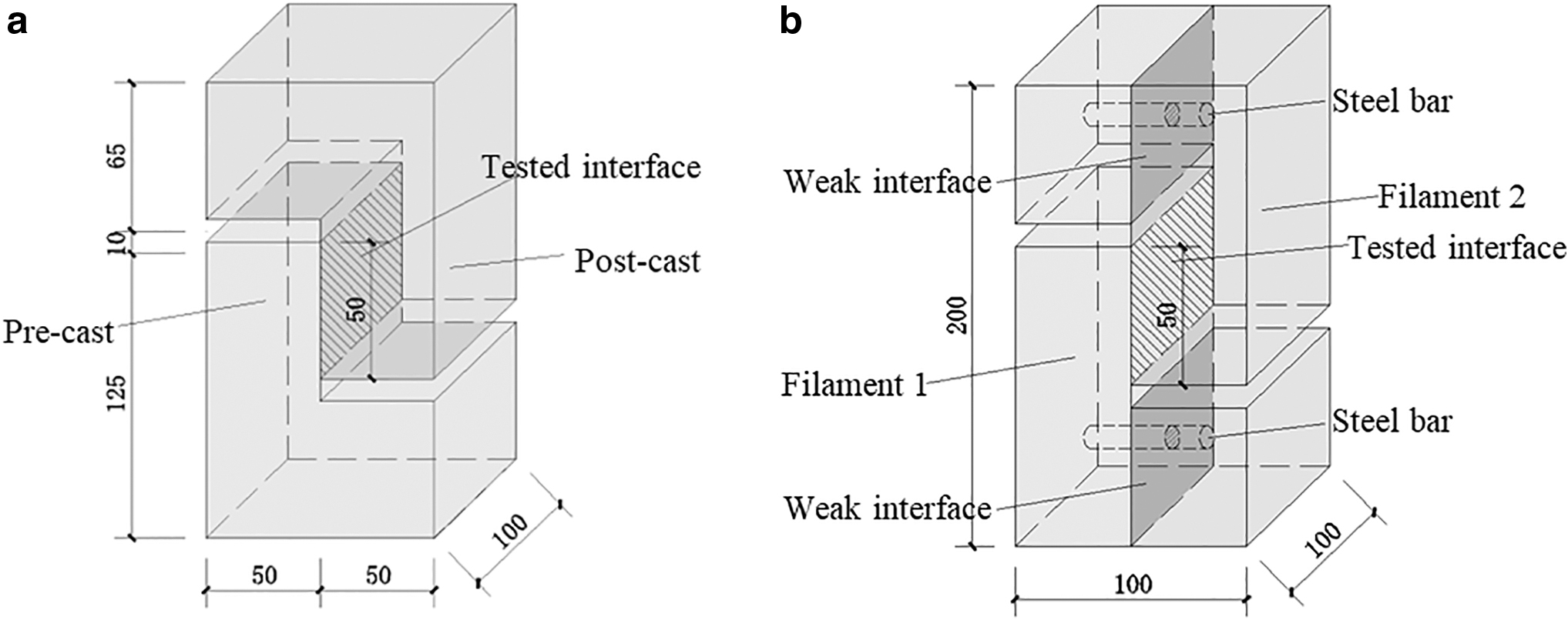
Diagram of cast and printed L-shaped specimens.

Shear stress distribution of tested interfaces of L-shaped with or without steel bar enhancement.
It is found that the difference of shear stress between the two tested interfaces is less than 1%, showing no obvious influence on the stress distribution of the tested interface. In general, the optimized L-shaped shear specimen can effectively test the shear behavior of interlayer and interstrip interfaces in 3D printed concrete.
Specimen parameters
In addition to the interface types (both interlayer and interstrip interfaces), the replacement ratios of recycled sand (0%, 25%, 50%, 100%), printing time intervals (continuously printing 0, 30, 60, 120 min), and surface treatments (using cement paste, using epoxy paste, wetting surface, and no treatment), were also intensively studied. The printing time interval is one of the key factors affecting the bonding properties of interface between cement-based materials. 30 The different printing time intervals were selected to represent the different hardened states of printed filaments to check if the recycled mortar is more sensitive to the printing time intervals. The filaments were in the states of “before initial setting,” “initial hardening,” and “almost finish initial setting” after printing at 30, 60, and 120 min, respectively. Regarding the surface treatments, cement paste and epoxy paste were selected in this study as commonly used interfacial agents, while surface wetting was a simple treatment without extra expense.
Specimens with no surface treatment were set as control groups. Interfacial agents were brushed during printing process, whereas moisture was sprayed. The thickness of the interface agent was 1 mm. The surface of printed filaments was completely saturated when wetting.
Considering the above factors, 32 groups of specimens were designed in this study, 3 specimens for each group, as shown in Table 3. The specimens were termed using four parts. First part, R0 to R100 referred the different mortar mix proportions. Second part, the letters L and S referred to interlayer interface and interstrip interface, respectively. Third part, the number 0 referred to continuously printing, whereas numbers 30 to 120 meant the different printing interval time ranging from 30 to 120 min. The fourth part, letters CP, EP, W, and N represent using cement paste, using epoxy paste, wetting surface, and no surface treatment, respectively. It is worth noting that the research object in this article is the interfacial shear performance of 3DPC in the hardened stage. Therefore, independent variables such as rheological properties and extrusion parameters were controlled within a certain range.
Specimen Details and Test Results
Specimen preparation
The self-developed extrusion printer was used in this study, as introduced in previous studies. 45 Considering the fixed size of printed filament with a width of 30 mm and a height of 15 mm, 250 × 120 × 120 mm specimens were printed for interlayer interface specimen, and the interface between the fourth and fifth layers in the deposition direction was taken as the tested interlayer interface, as shown in Figure 5a. For interstrip interface, 250 × 120 × 105 mm specimens were printed and the interface between the second and third filaments in the translation direction was taken as the tested interstrip interface, as shown in Figure 5b.
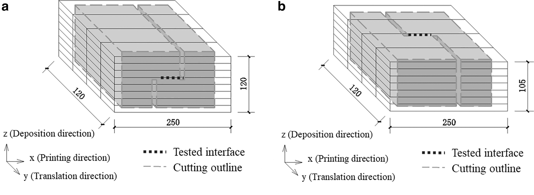
Schematic diagram of printed specimens.
The printing processes of interlayer interface specimens and interstrip interface specimens were slightly different, as demonstrated in Figure 6. The printed mortar was prepared 5 min before each printing process to ensure the similar properties of printed filaments. Steel bars were inserted perpendicularly in the middle of inferior interface so as not to obstruct the printing path of nozzle during subsequent printing. The specimens were cured under ambient temperature of 20°C ± 2°C and relative humidity of 95% ± 5% for 28 days before cutting.

Specimens preparation processes.
Test setup and loading procedures
The specimen was loaded by one WDW-300 electronic universal testing machine. Two 50-mm-thick steel blocks were set on both sides to guarantee the specimens being under uniform loading, as shown in Figure 7. Due to the brittle failure of the specimen, the loading speed should be low enough for camera to capture the initial crack appearance during digital image correlation (DIC) process. The loading speed was set as 0.05 mm/min. The DIC method was used to record the crack development and failure characteristics when loading.

Schematic diagram of shear specimen loading.
Assuming that the shear stress is uniformly distributed along the tested interface, the interfacial shear stress τ can be calculated according to Equation (1)
where, F is the loading force; S is the measured area of tested interface, which was measured by a vernier caliper before loading. When F reaches the ultimate load Fmax, the interfacial shear strength τmax can be calculated.
Results Analysis
Failure patterns and interfacial shear strength
The typical failure process of the specimen under shear is shown in Figure 8. The cracks of the improved L-shaped shear specimen propagated along the tested interface. The failure pattern under shear was obviously brittle failure. During the loading process, cracks first appeared along the interface, gradually propagated, and then failed completely. The upper part of the specimen suddenly dropped down. It is worth noting that regardless different parameters, cracks are parallel to the interface, and no flexural cracks were found during the failure process of the L-shaped specimen. It indicates that all specimens are approximately pure shear failure with little bending influence.

Typical failure process.
The typical shear strain distribution of tested interface when the initial crack appeared was measured by the DIC during the loading process, as shown in Figure 9. It can be seen that the shear strain distribution along the interface was basically uniform. Therefore, it is reasonable to take the average shear stress to evaluate the shear behavior of the interface for 3D printed recycled mortar. The test results are listed in Table 3.
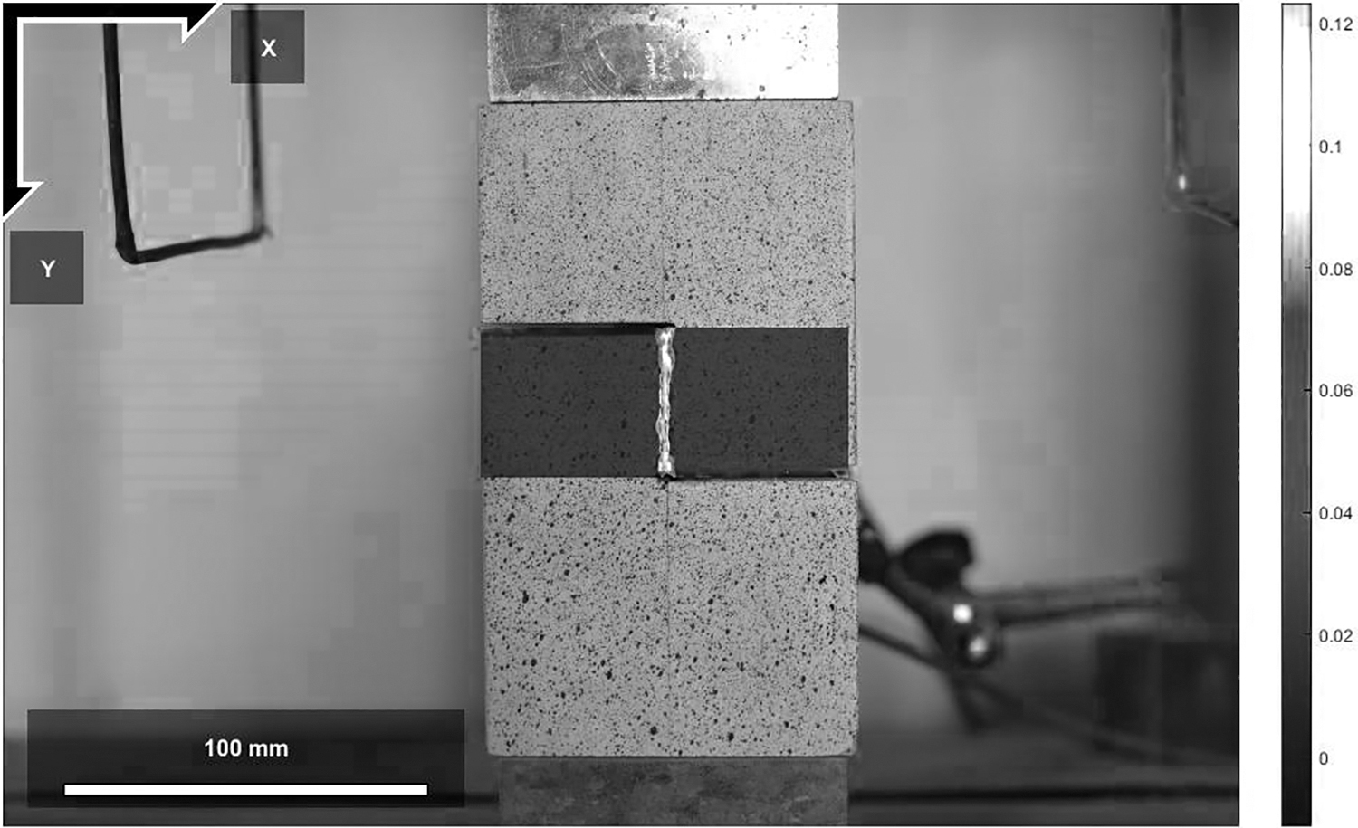
Diagram of shear strain distribution.
Effect of replacement ratio of recycled sand
The specimens without printing interval and surface treatment were selected to evaluate the effect of replacement ratio of recycled sand, as drawn in Figure 10. It is obvious that the interfacial shear strength decreased with the increase of the replacement ratio of recycled sand. When the replacement ratio increased from 0% to 25%, the interfacial shear strength dropped only 3% to 4% for both types of interfaces. When the replacement ratio increased to 50%, the shear strength of interstrip interface decreased to 78% in control group, lower than 91% of the interlayer interface. It can be noticed that, when the replacement ratio ranged from 0% to 100%, the interfacial shear strength decreased about 20% for both types of interfaces, lower than the 30% decrease of mortar compressive strength, indicating that the interfacial bond strength was relatively slightly affected by the replacement of recycled sand compared with compressive strength.
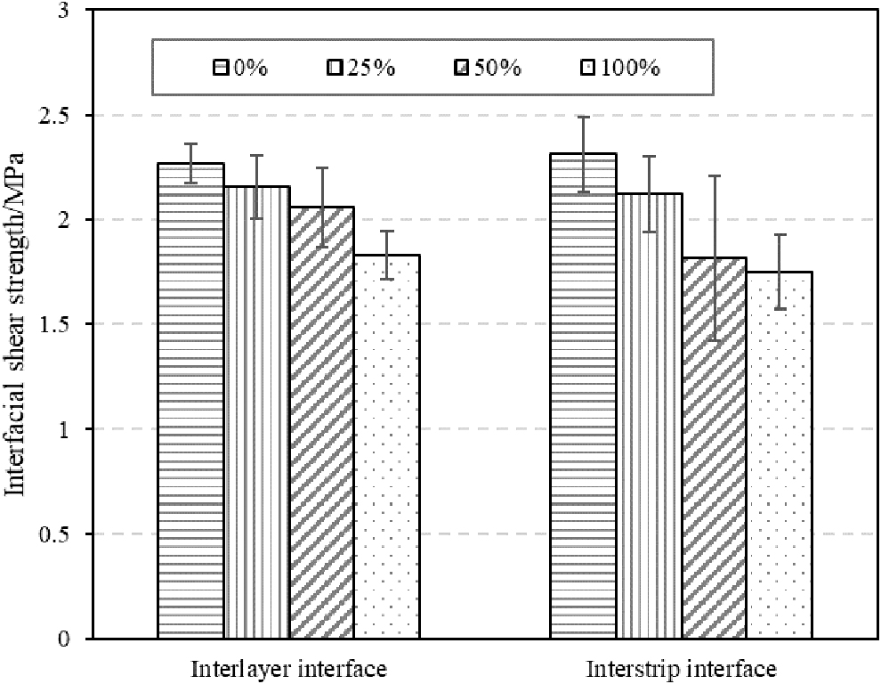
Effect of replacement ratio of recycled sand on interfacial shear strength.
The negative effects of the recycled sand can be divided into two aspects. On the one hand, the mechanical properties of recycled mortar are inferior to natural mortar, due to the higher porosity, more microcracks, and more water transfer channels of recycled sand, as shown in Figure 11. On the other hand, the recycled mortar hardened obviously faster than natural mortar with a higher early strength, 44 due to the higher water absorption rate of recycled sand, which may have a negative influence on the adhesion of interfaces.
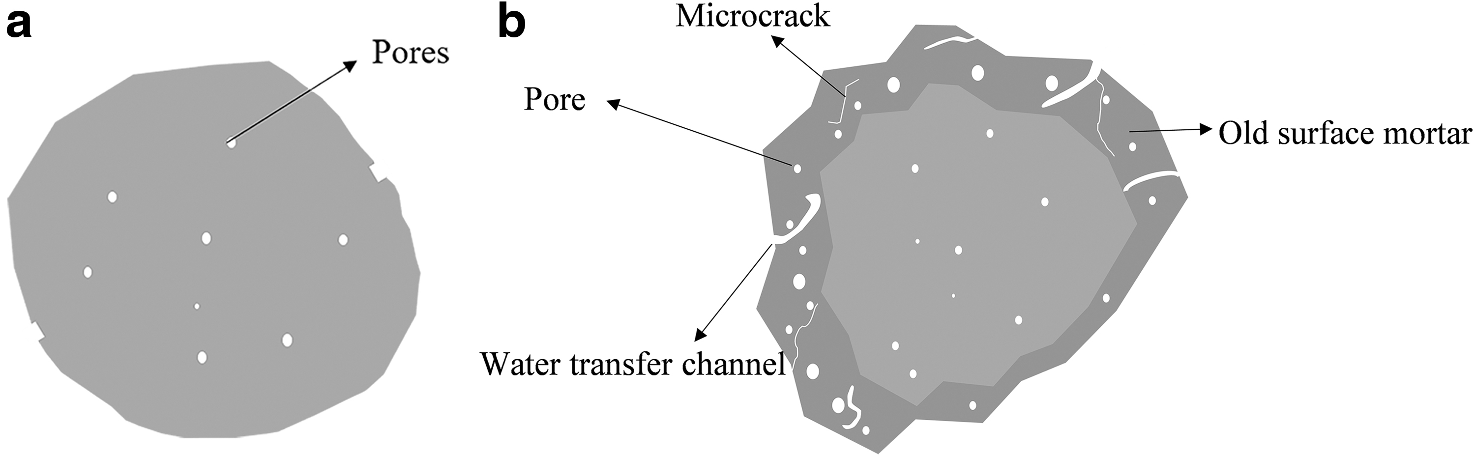
Micro pore characteristics between natural and recycled sand.
Effect of printing intervals
The shear strength of specimens with different printing intervals are displayed in Figure 12. It should be noted in the continuously printing process that the printing intervals for interlayer interfaces and interstrip interfaces were nearly 1 min and 15 s, respectively. For simplicity of expression, the continuous printing process was denoted as “0 min.” With the extension of printing interval time, the interfacial shear strength decreased significantly, showing that the effect of different printing intervals is more obvious compared with the replacement ratios of recycled sand. It can be noticed that there are different “turning points” of interfacial shear strength of natural mortar specimens and recycled mortar specimens at the printing intervals of 30 and 60 min, respectively. For natural mortar specimens, the shear strength of interfaces dropped obviously when the printing interval increased from 0 to 60 min. After 60 min, the decline tended to be steady. For recycled mortar, the shear strength of interfaces decreased sharply when the printing interval reached 30 min, then the strength dropped slightly when the printing interval increased to 60 and 120 min.

Effect of printing time intervals on interfacial shear strength.
The turning point of recycled mortar is earlier than natural mortar, showing that the interfaces in 3D printed recycled mortar had higher time sensitivity compared with 3D printed natural mortar, which is related to the hardened properties of printed mortar. After preliminary hardening, the influence of printing interval has little effect on the interfacial shear strength. It can be observed during the printing process that, after an interval of 30 min, the printed recycled mortar preliminarily hardened, whereas the natural mortar was still in a semisolid state until 60 min. The hardened state was simply tested by gently pressing the printed filaments.
It should be mentioned that, when the printing interval reached 60 min, the strength of all interfaces decreased to lower than 60%, which indicated that the discontinuity of printing significantly had a negative influence on the shear strength of 3D printed interface, which should draw more attention. This is because that the interfacial bond strength was closely related to the rest time of printing mortar,30,32 more precisely, the flow state of the printing mortar. When printing continuously, the printed filaments on both sides of the interface were fresh, enabling the filaments to stick well to each other under gravity and squeezing. After curing, only some small pores can be found along the interface, as shown in Figure 13a. On the contrary, when printed with time interval, the first printed filaments had already preliminarily hardened with somewhat strength and stiffness, losing the fluidity and deformability. The water evaporated from the filament surface also inhibited the hydration activity in the interface area when the subsequent filament printed.46,47
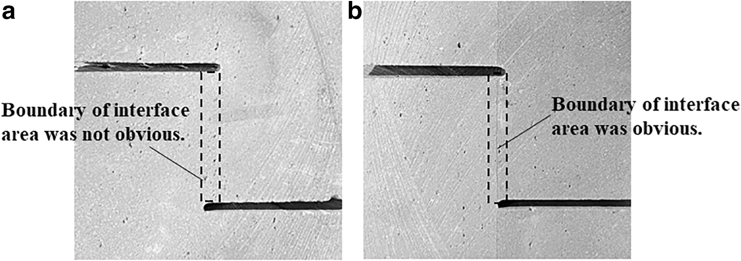
Effect of printing time intervals on morphology of interface area.
More pores were also introduced into the interface area by water transfer process because of the high moisture content gradient between former and latter printed filaments. 31 As a result, for the interface specimens with printing interval, an obvious outline of interface can be observed after curing, as shown in Figure 13b.
Effect of surface treatment
As shown in the above analysis, the interfacial properties degraded significantly with the increasing printing intervals, which would increase the insecurity of 3D printed structure. Therefore, the printing interval of 120 min, representing the discontinuous construction situations of 3DPC structure, was selected to evaluate the enhancement effect of some commonly used surface treatments. The influence of different surface treatments on the interfacial shear strength of natural mortar and recycled mortar is demonstrated in Figure 14. The specimens without interval were taken as the baseline, whereas the specimens with intervals without surface treatment were selected as the control group.

Effect of surface treatment on interfacial shear strength.
In general, three surface treatment methods can improve the interfacial shear strength to a certain extent. Epoxy paste has the best enhancement effect, followed by cement paste. Surface wetting without using interface agent can also improve the interfacial performance but to a limited extent.
For natural mortar, the effects of surface treatments on both interlayer interface and interstrip interface were similar. The cement paste could increase the interfacial shear strength from 1.07–1.11 to 2.00–2.23 MPa by 80–108%. Epoxy paste could increase the interfacial shear strength by more than 200%, much higher than the baseline, which was consistent with the results reported in literature. 27 In addition, the strengthening effect of surface wetting was lower than epoxy paste, and cement paste increased by about 40–50%. As for recycled mortar, the effects of different surface treatments were similar to that of natural mortar. However, the enhancement effects on interstrip interface were obviously higher compared with interlayer interface.
Using cement paste and epoxy paste can fill the gap between filaments and increase the effective bond area through the filling and expansion effect. 18 Besides, the paste also has the property of compensating shrinkage and could prevent the formation of microcracks in the interface during the hardening process. In addition, surface wetting can promote the hydration reaction by compensating for the evaporation of water, so that hydration products were better formed between the former and latter printed filaments. It is an effective and convenient method to enhance the interfacial properties. However, the excess water might increase the water–cement ratio of filaments and the porosity at the interface area, then aggravate the interfacial shear strength. Tao et al. 29 pointed out that excessively higher moisture may have a negative impact on the interface bonding and long-term performance of the printed structure.
Discussions
The specimens of different interface types under the same conditions were selected for a comparative analysis, as depicted in Figure 15. The X-axis is the interlayer interfacial shear strength, namely τl,max, whereas the Y-axis is the corresponding interstrip interfacial shear strength under the same condition, namely τs,max. It is obvious that the shear strengths of two types of interfaces are approximately similar, especially under situations without surface treatments. This is mainly thanks to the adequate previous researches of printability of 3D printed cementitious materials. 43 The appropriate mix proportions of printed mortar and the corresponding printer settings allowed the good contact between filaments without obvious gaps. Meanwhile, it can be inferred that the anisotropy of 3DPC mainly root in the interface numbers, distributions, and interface strengths, instead of the difference between the interlayer interfaces and interstrip interfaces. 48
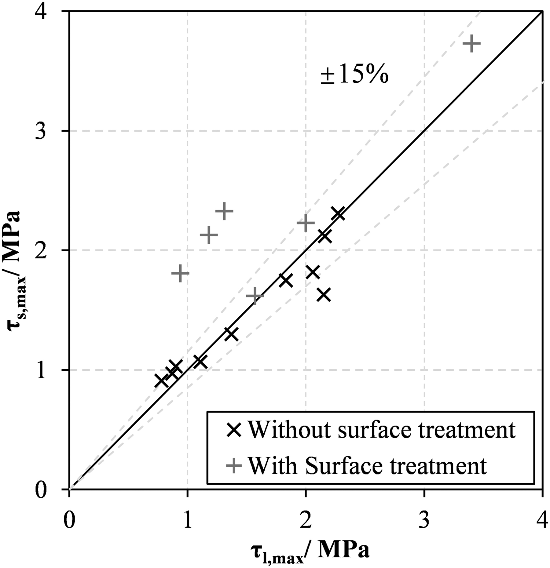
Comparison of interlayer interfaces and interstrip interfaces.
The test results also show that for the continuously printed specimens with different recycled sand replacement ratios, interlayer interfaces are slightly stronger than interstrip interfaces, which is consistent with the previous study by Wang et al., 39 because of the additional extrusion pressure for the interlayer interface provided by gravity of the latter printed mortar. In addition, although few studies were conducted to evaluate the influence factors on the difference between interlayer interface and interstrip interface, it can be inferred that the strength of interlayer interface and interstrip interface is related to both the printed material properties and printer settings. The strength of interstrip interface may significantly drop without good contact between filaments. Therefore, the strength difference between two types of interfaces obtained in this study is not completely applicable to all printing situations, which needs further investigation.
As mentioned above, the test results show that an obvious inferior interface will appear in the 3DPC structure after a printing interval of 30–60 min. In general, 3DPC building structure needs to be completed by several printing phases due to the limitations of materials and printing processes. Thus, the inferior interface will inevitably exist in the 3D printed concrete structures by a discontinuous construction process. 49 These inferior interfaces should be considered in the 3DPC construction by properly designing the discontinuity position, enhancing the interface by suitable surface agents, to avoid introducing extra insecurity by discontinuous construction. The test results confirm that the epoxy paste and cement paste can effectively improve the interface strength, which are recommended to deal with the inferior interface in the process of discontinuous printing. Wetting can also improve the surface strength to some extent. In addition, according to Figure 14, the effects of surface treatment on the two types of interfaces of natural mortar are similar, while those on the recycled mortar are somewhat different.
More exactly, for 3D printed recycled mortar, the effects of surface treatments on interstrip interface are much better than those on interlayer interface, as shown in Figure 14b. This may be influenced by gravity and high water absorption of recycled sand. The surface moisture of interlayer interface may be lost more obvious under gravitation forces than interstrip interface, 46 which is also aggravated by the high water absorption of recycled sand. Thus, the lack of surface moisture may have an adverse effect on the chemical reaction of surface agents. However, the experimental data are insufficient to fully explain this phenomenon, so that the interaction of recycled sand and surface treatment as well as the effect mechanism on different types of interfaces should be further studied.
Conclusions
One novel L-type shear test method was proposed in this study to investigate the effect of different replacement ratios of recycled sand, printing time intervals, and surface treatments on the interfacial bond properties of 3D printed interlayer and interstrip interfaces. The failure pattern under shear loading was obviously brittle failure. During the loading process, cracks first appeared along the tested interface, gradually propagated, and then the specimens failed completely.
Under the same printing condition, the interfacial shear strength of interlayer interface and interstrip interface was similar. The high water absorption and porosity of recycled sand had an adverse effect on the interfacial shear strength. When the replacement ratio of recycled sand increased from 0% to 100%, the interfacial shear strength decreased nearly 20%.
The interfacial shear strength significantly decreased with the extension of printing time interval. The printing interval of 30 and 60 min led to 60% strength decrease for recycled mortar and natural mortar, indicating that the interfaces in 3D printed recycled mortar had higher time sensitivity compared with 3D printed natural mortar. In addition, for both natural and recycled mortar, the interfacial shear strengths with the printing interval of 120 min were lower than 50% of those of interfaces formed by continuously printing. Discontinuous construction will inevitably introduce obvious inferior interfaces in 3DPC structures, which should be enhanced by effective surface treatments. The improvement effect of surface treatments was epoxy paste > cement paste > surface wetting > no treatment.
Footnotes
Author Disclosure Statement
No competing financial interests exist.
Authors' Contributions
Ziyue Wang: Writing—original draft (lead); formal analysis (lead); and writing—review and editing (equal). Zixuan Chen: Writing—review and editing (equal). Jianzhuang Xiao: Conceptualization (lead); Supervison; Resource; and writing—review and editing (equal). Tao Ding: Methodology (lead); and writing—review and editing (equal).
Funding Information
The financial support from the National Natural Science Foundation of China (No: 52078358), Shanghai Rising-Star Program (No: 22QC1400800), and the State Key Laboratory of Solid Waste Reuse for Building Materials (No: SWR-2021-003) are highly acknowledged.