
Abstract
A new method for producing parts in the expanding sector is additive manufacturing. The appropriate name for three-dimensional (3D) printing is additive manufacturing because it produces the part layer by layer. Plastics and metals can be 3D printed in large quantities with the precise surface finish and feature quality needed in additive manufacturing. More specifically, direct metal sintering, direct energy deposition, and metal binder jetting are used in 3D printing. The computer-aided design model is completed when the powder bed has been successively scanned and lowered. The metal sintering process uses a powder bed with powder metal, and laser selectively melts a flattened bed of powder, which is done with roller with successive rolling of new layer on previous into desired shape before a new layer is pushed on top of the previous layer. As a result, the new layer has solidified on top of the earlier layer, causing the prior layer to melt back again. Because of the unique thermal cycle, this results in residual stress (RS). The unique thermal cycle of metal additive manufacturing is characterized by (1) rapid heating rate caused by high energy intensity and steep temperature gradients; (2) rapid solidification with high cooling rates because of the small volume of melt pool; and (3) melt back, which involves simultaneous melting of the top powder layer and re-melting of underlying previously solidified layers. The presence of RS in metal additive manufacturing (AM) creates difficulties that restrict the process's ability to produce parts at an industrial scale. During and after manufacturing, these forces may cause parts to distort and crack. This can be solved by heating the powder bed, which will lessen this type of issue. The causes, traits, and reduction of RS are the main topics of this review article. A number of conceptual approaches to reducing RS are addressed to provide some useful inspiration for creating a methodical RS balancing procedure for AM. These approaches are based on the state and future of the relevant techniques.
Introduction
Metal additive manufacturing (AM) is a sophisticated processing technology of growing industrial significance because of its unique benefits and ability to create complex structures with high-performance materials.1,2 With the help of this developing technology, products can be created using liquid or semisolid, powder, or solid, and then given their ultimate shape. 3 AM technologies enable complicated geometry and functional part creation by gradually adding thin layers of metal based on a digital model without the need for tooling and assembly compared to conventional manufacturing techniques.4,5
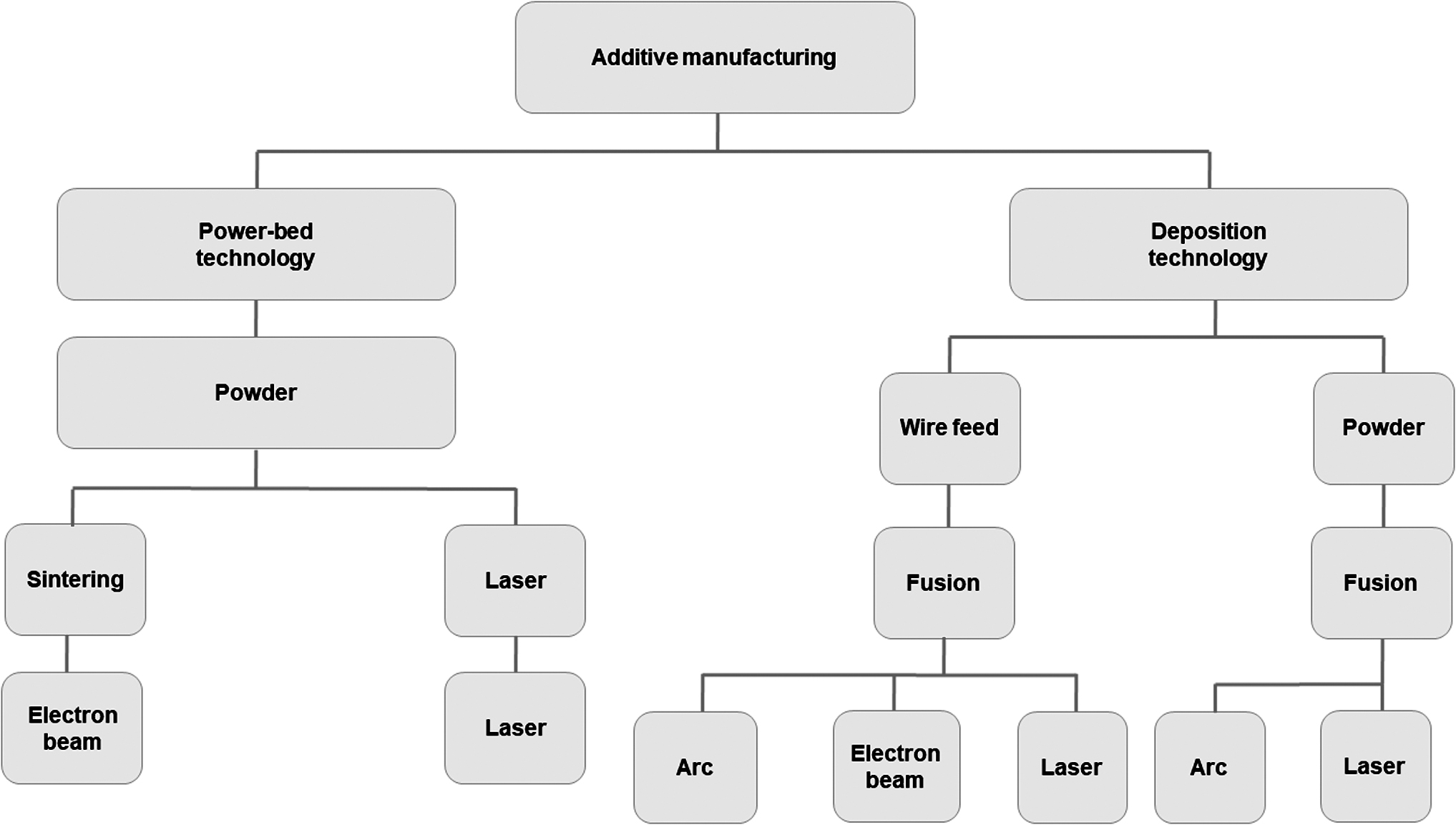
Depending on the material deposition, AM (Fig. 1) can be divided into two types such as powder bed fusion (PBF) and directed energy deposition (DED). High-intensity beam, either laser or electron beam, is utilized to completely melt layers of metal powder in an inert or vacuum environment to create a three-dimensional (3D) product. Another type of PBF process is electron beam melting (EBM), which was first made commercially available by Arcam. EBM uses an electron beam as a heat source to melt metal powder materials in a high vacuum chamber with a layer thickness (100 m) that is usually greater than laser PBF process. 6

AM methods:
When compared to selective laser melting (SLM), a significant amount of powder bed preheating is used in EBM to lower the temperature gradient and residual stress (RS) of the build. 7 In contrast to PBF, DED manufactures parts by immediately melting feed stock material, while feeding wire or powder. Heat source in DED is typically a laser or electron stream, similar to PBF. However, due to the thicker layer thickness and greater energy deposition rate, DED has a much higher material deposition rate than PBF.8,9 The disadvantage of DED, however, is that it has lesser part accuracy than PBF. Other metal AM techniques, such as binder jetting or metal fused deposition modeling, use a binder agent to create a green component first, which is then sintered to produce a part that is nearly fully dense. 10
In AM components, extreme RS usually grows. RS (Fig. 2) is the stress that remains in the body without any externally applied load. 11 They are also called internal, or locked in stress, which can strengthen or weaken a part. 12 It is also referred to as thermal stress; hence, their origin is from thermal gradients during the manufacturing process. RS normally reduced the yield strength of the final component and results in high geometric deformation. 13

Residual stress in AM process.
The applications and acceptance of AM components have been severely constrained by the RS that forms during production, which can significantly change mechanical properties, particularly in cyclic loading. 14 Moreover, RS in-process may cause severe geometric distortion, which could lead to failure of the manufacturing process. 15 The problems that arise with this production process in large scale in economic point of view include cost of powder, cost of machines, and production time restricts its applications in higher cost fields such as aerospace and medical industries.
RS often relates to AM and machining parts. For instance, Bartlett et al. 16 developed a nondestructive method for RS measurement in SLM with the help of 3D digital image correlation (3D-DIC) to capture in situ surface distortion. A two-dimensional analytical model was established to convert DIC surface curvature analysis to measure in-plane RS. The RS measurement by 3D-DIC was confirmed by X-ray diffraction (XRD). The variation in RS was associated with sector-based laser raster strategy and was sustained by finite element (FE) calculations. The results from the calculations revealed heterogeneous RS distribution in reheating and cooling parts of new surface. The DIC-based RS methodology leads considerable advantage over in situ AM RS measurements. Croom et al. 17 report 3D DIC-based method for in situ discerning of RS in air plasma spray coatings.
The details of RS of three-layer thermal barrier coating system (TBC) were obtained experimentally using 3D-DIC curvature measurement from 22°C to 800°C coupled with freshly developed RS model for multilayered TBC system. The results found a peculiar rise in curvature and RS with heating between 800°C and 900°C. This might be due to expansive tetragonal to monoclinic phase transformation within partially stabilized Zirconia top coat. Hence, the method creates new possibilities for examining the development of RS throughout the production and use of coatings, thin films, and structures made of dissimilar materials.
RS is often associated with the formation of defects that are also critical to AM parts. Several work has been published. For instance, Bartlett et al. 18 worked for the prediction of microstructural defect in AM from powder bed quality using digital image correction. A new method by incorporating in situ 3D-DIC was developed. The results concluded peculiarities in the powder bed were identified, and their geometries evaluated layer by layer by 3D-DIC study. A Naive–Bayes classification algorithm was used to estimate the possibility of physical defect generation based on the severity of in-process powder bed errors using the quantified powder bed 3D-DIC data and ex situ detection of physical fault locations.
This technology has the potential to be utilized to forecast the occurrence of physical defects based on detection in-process mistakes in powder spreading before the occurrence of many microstructural faults. Bartlett et al. 19 investigate in situ defect in AlSi10Mg specimen during SLM production through full-field infrared thermography. Using layer wise relative surface temperature measurements, subsurface flaws were found by their retained thermal signature at the surface. Transient thermal modeling was done to validate these data. Ex situ scanning electron microscopy was used to characterize parts to confirm data identifying faults and, crucially, to assess detection success. The infrared radiation (IR) defect detection approach was quite successful in locating defects, with an 82% overall success rate for lack of fusion (LoF) faults; detection success increased with defect size.
The approach was utilized to statistically analyze the presence of systematic process defects during SLM production, enhancing the capabilities of IR monitoring techniques. This special analysis technique and straightforward combination for in situ IR monitoring can quickly enhance nondestructive qualification techniques used in SLM processing. Holzmond and Li 20 worked in situ real-time defect detection of 3D printed parts. The authors introduce a “certify-as-you-build” quality assurance system that can track a part during printing, capture its geometry using 3D-DIC, and assess the printed geometry against the computer model to identify print errors as they happen. A test case exhibiting in situ error identification of localized and global faults was built, utilizing a fused filament fabrication 3D printer.
Lu et al.21,22 measured the RS and deformation of Ti-6Al-4V with an FE model, calibrated using situ system, in addition with thermocouples, infrared imaging sensor, DIC, and displacement sensor, which can calculate the temperature and deformation of Ti-6Al-4V parts developed by DED. Numerous studies have been done on the optimization of the process to lessen RS and deformation.
It has been discovered that minimizing RS and warpage can be achieved by optimizing the deposition order or process parameters23,24 and preheating the substrate before the AM. 25 However, due to the use of a high-energy beam as the heat source, such methods based on controlling the thermal gradients in metal AM are restricted. For instance, preheating the substrate or build chamber may raise the risk of coarsening the microstructure; the path optimization and optimization of process parameters are quite difficult and must require the inspection of microstructural growth. Moreover, the use of auxiliary tools during AM or postprocessing stress relieving26,27 benefits stress reduction, but enhances both manufacturing time and cost.
Nature uses 3D printing of hard phase in soft matrix in biological materials without RS. The biological materials (nature AM manufactured) exhibit more mechanical robustness than man-made materials. Li 28 investigated structural and mechanical characterization of natural nanocomposites: Sea shells. The author focused on structural and mechanical properties in nacre (mother-of-pearl). The result showed that the two main mechanisms causing energy to be lost in nacre are rotation and deformation of aragonite nanoparticles. The particle rotation process is facilitated by the biopolymer space between nanoparticles. Zhang and Li 29 worked in uncovering aragonite nanoparticle self-assembly in nacre. Nacre (mother-of-pearl), which has exceptional mechanical strength and exceptional durability, has long been recognized as the best natural Armor. In this study, the authors describe for the first time their first-hand observation of the development of dome-shaped platelets and the self-assembly of aragonite nanoparticles in the nacre of the bivalve Perna viridis.
During the early stages of platelet formation, the aragonite nanoparticles were discovered to first self-assemble into a core shell structure, forming a dome-shaped platelet, in accordance with the predetermined pattern. The dome-shaped platelets are piled one on top of the other to create an interlocking network that prevents the platelets from sliding, greatly enhancing the strength and toughness of nacre. The discoveries help us better understand how nacre is formed, offer fresh design recommendations for creating bioinspired materials, and establish a constitutive basis for simulating nacre's deformation behavior. Li et al. 30 carried out nanoscale structural and mechanical characterization of the shell of a red abalone. Cobble-like polygonal nanograins are the fundamental building elements that are utilized to assemble individual aragonite platelets into the mother-of-pearl structure known as nacre.
The aragonite platelets with micro grain structures are relatively ductile in nature rather than brittle. The aragonite platelet deformation, crack deflection, aragonite platelet slip, and organic adhesive interlayer contribute to the nacre's fracture toughness. Cracks that developed in the outer prismatic layer of shell do not indicate the crack diversion mechanism. Li et al. 31 reported in situ dynamic atomic force observations of nacre with nanograins (Nano particle) of average grain size of 32 nm, which reveal that nanograin rotation and deformation are two important mechanisms that contribute to energy dissipation in nacre. The biopolymer gap between the nanograins eases the grain rotation process. The aragonite nanograins in nacre are not brittle, but are ductile in nature.
This article focuses on the various metal AM techniques. It reveals the primary mechanism that causes AM's RS and thoroughly evaluates available control measures. Various RS measurement methods are compared according to the advantages and disadvantages. It also covered basic RS in depth.
3D Printing Process
The procedure incorporated in 3D printing (Fig. 3a) of part model includes concept model that is subsequently created in modeling software and given the name computer-aided design (CAD) model of the concept part. Before being finalized, this CAD part model is thoroughly examined in terms of its dimension after printing, RS in part, tolerance, printing time, and all other relevant variables. 32
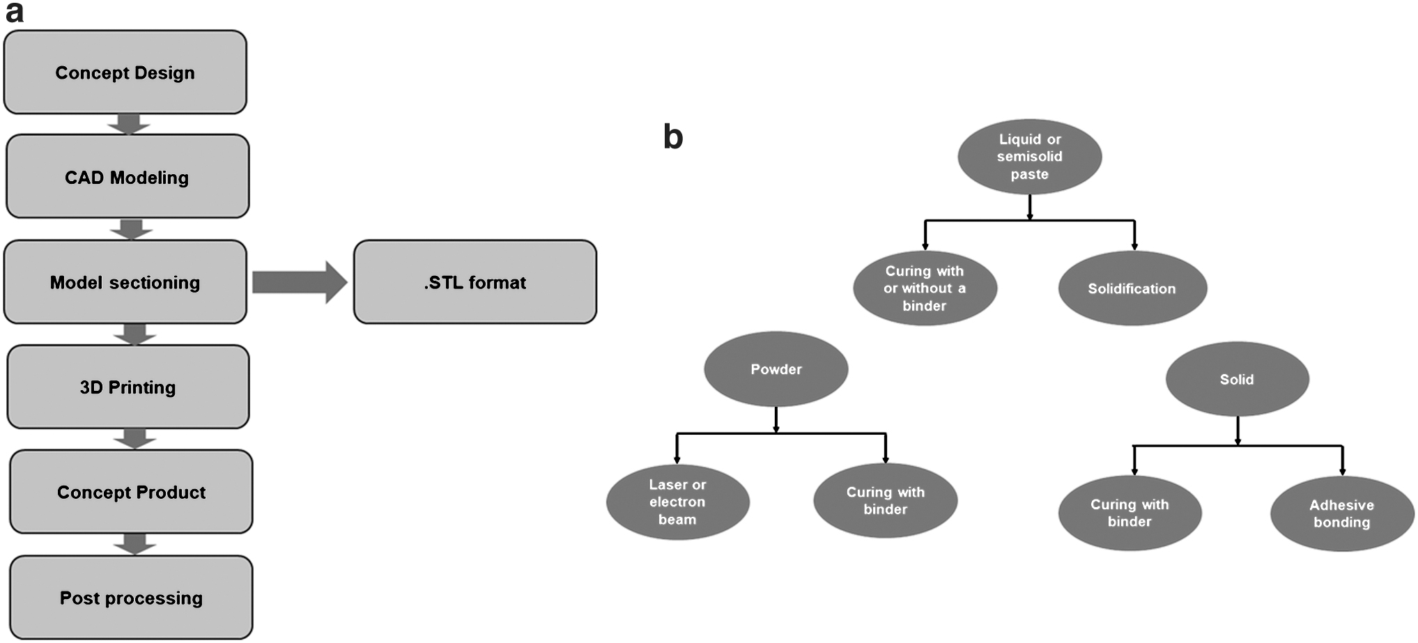
A CAD model is prepared for model sectioning—is a process in which the model is divided into layers and then printed in three dimensions. The CAD model is presented to the 3D printer in stereolithography format so that it can create the component by addition of one layer over another. The various raw materials for 3D printing (Fig. 3b) include liquid, semisolid, and powder particles. Stereolithography and digital light projector uses both liquid and semisolid raw materials. The product is drawn out of this liquid using a ultraviolet laser that is concentrated on a liquid photopolymer resin bath. For solid-state 3D printing, the curing with binder or sticky bonding is used. To create the finished result, these curing binders join the solid particle. 3D printing with direct metal sintering, selective laser sintering (SLS), DED, and metal binder injection works with metal powder.
Aluminum powder is used in the AM of metals to create 3D components. Due to stainless steel's strength, light weight, resistance to heat up to 831°C, and rapid production, stainless steel powder can be used to create 3D printed components. 33 Brass is simple to print, and copper powder is also used to create copper components because it resists corrosion, has excellent thermal resistance, and is simple to join. The printing of gold and sterling silver powders allows the creation of intricate jewelry designs. Aerospace component manufacturing, bulk customization, and off-site production use titanium powder.
Types of AM
3D printing process (Fig. 4) involves SLS, EBM, DED, also called laser deposition welding, and metal powder application (MPA). In SLS method, a powerful beam is focused on a bed of metal powder—fuses the metal powder particles to form a layer. In EBM method, a beam of electron is concentrated on powder bed; however, in DED process, metal powder bed is put in a protective gas stream, melted, and a required solidified layer is obtained. The MPA method utilizes accelerated particles along with carrier gas that is put in previous layer; it results in distortion of powder and surface producing an adhesive contact surface. Among all the methods, SLS is most commonly used for manufacturing metal parts. It employs a metal powder bath attached to piston arrangement, for raising and lowering the powder bed to add the layer of powder.
Types of AM.
With the help of concentrating guides, the laser is directed at metal powder. A laser head and optical fiber are used to create this laser beam. An article on the solidifying behavior of metallic powder in SLM process was published in 2017 by Abe et al. 34 Cu, Fe, Al, Sn, and stainless steel powder were used in their work to study the solidification behavior of these metals. Experiments were carried out by the authors with these combination of metals, and revealed that powder that solidifies in continuous line has a round cross-section. It also represents the crescent cross-section that creates dense models. Cu and Fe represent the continuous line. Al and stainless steel reveal discontinuous solidified tracks. However, these solidified tracks are not sufficient for 3D printing and the upgradation of solidified tracks is obtained with the help of vacuum and powder mixture.
Residual Stress
RS is a self-equilibrating stress that remains on the part after manufacturing and heating, and arises when a part experiences plastic deformation. 15 RS evolves and modifies in each and every step of production and possesses a remarkable effect on resources and durability; the effects of RS are highly dependent on orientation and magnitude and may be either advantageous or damaging to material performance. Moreover, in view of additive parts, RS can be reduced by postheat treatment process; the spread of more in-process RS causes huge deformation that results in inaccuracy or collapse in manufacturing. It is very crucial to recognize RS in manufactured parts. The complicated process of AM method leads to subsequently complex RS growth in parts.
Classification and stress formation model of RS
RS may have a number of unfavorable effects on the part's characteristics, including poor fatigue resistance, failure during working, and lower chemical resistance, lower deformation resistance, and poor static and dynamic strength. The origin of RS can be due to the service loading, and therefore generates inhomogeneous plastic deformation. These stresses are found in both finished parts and raw materials. The origin of RS can be divided into four groups: 15
Dissimilar plastic flow
High heating and cooling rates
Phase transitions accompanied by volume changes
Chemical-induced misfit
The majority of AM methods involves rapid heating caused by the energy source (laser, electron, or plasma), which causes the metal or alloy to melt and then solidify further (powder based). The local structure and characteristics of components are impacted by repeated heating and cooling. 35 Due to the rapid cooling and heating, RS is created, which may result in deformation, fractures, and a reduction in the performance of AM-produced materials. The anisotropic properties developed in the part are another immediate effect of RS. 36
The temperature gradient mechanism (TGM), depicted in Figure 5, can be used to describe the causes of RS in AM. In the irradiated zone, the power source's heating causes a number of local elastoplastic deformations (represented by ɛpl, ɛel, and σyield), as well as additional tensile tension. Contraction due to temperature produces shrinkage and results in the formation of tensile and compressive RS regions (upper and lower layers, respectively) during the cooling of molten top layers. 37
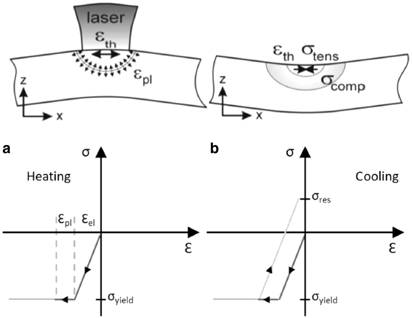
Temperature Gradient Mechanism Stresses and deformation during heating
RS is generally divided by the length scale in which they occur. 38
Type I: RS is macroscopic stress that acts on the component geometry's scale and distorts the component if boundary state is altered.
Type II: Micro RS, which takes place above the grain scale due to the existence of anisotropic property of the material.
Type III: nanoscale RS, which arises due to vacancy and deformations.
There is a particular distribution of RS for each AM method and material. Therefore, the distribution of RS will differ between two samples of the same material using various methods, such as EBM and SLM. 39 These methods result in complex stress field distributions and cause high anisotropy properties of RS. Kruth et al. 37 worked on layer postscanning inTi6Al4V and 316 L SLM samples. The results concluded that Ti parts showed 8% less distortion, while 316 L samples showed no reduction.
Another element that affects the spread and magnitude of RS is part geometry. Salmi and Atzeni 40 conducted a succession of RS measurements in AlSi10Mg parts produced by the SLM process using the hole drilling (HD) method. There were several different shapes created, including curved and flat (plates and hollow square cylinders) (circular and semicircular hollow cylinders). Curved walls were found to have slightly greater RS than flat walls, which is likely a result of closer-spaced hatches.
The unique rapid heating-cooling thermal cycle of AM is very similar to the welding process that causes RS in AM components. Mercelis and Kruth 41 referred to the TGM model and the cool-down phase model to describe the mechanism of RS formation. In the TGM model, during the heating stage, the feedstock material is heated quickly by a heat source with high energy intensity. The heated material has a tendency to expand, but this thermal expansion is constrained by the nearby material with lower temperature. This results in the origin of compressive stress at the heating zone. During cooling, a shrinkage occurs at the heating zone. However shrinkage is partly confined by the plastic strain that originated during the heating stage. Finally tensile RS is developed in the heated zone and this is counterbalanced by the compressive zone. 42
The scientific community has made substantial efforts to develop and improve models that can represent the dynamics of RS in AM processes. Many finite element method (FEM)-based computer models are described in the literature, along with a variety of different methods designed to reduce computational cost. 13
Tools to forecast RS in AM parts are being developed and improved by commercial software such as Ansys, ABAQUS, Autodesk, and Simufact, which uses multiapproach models.
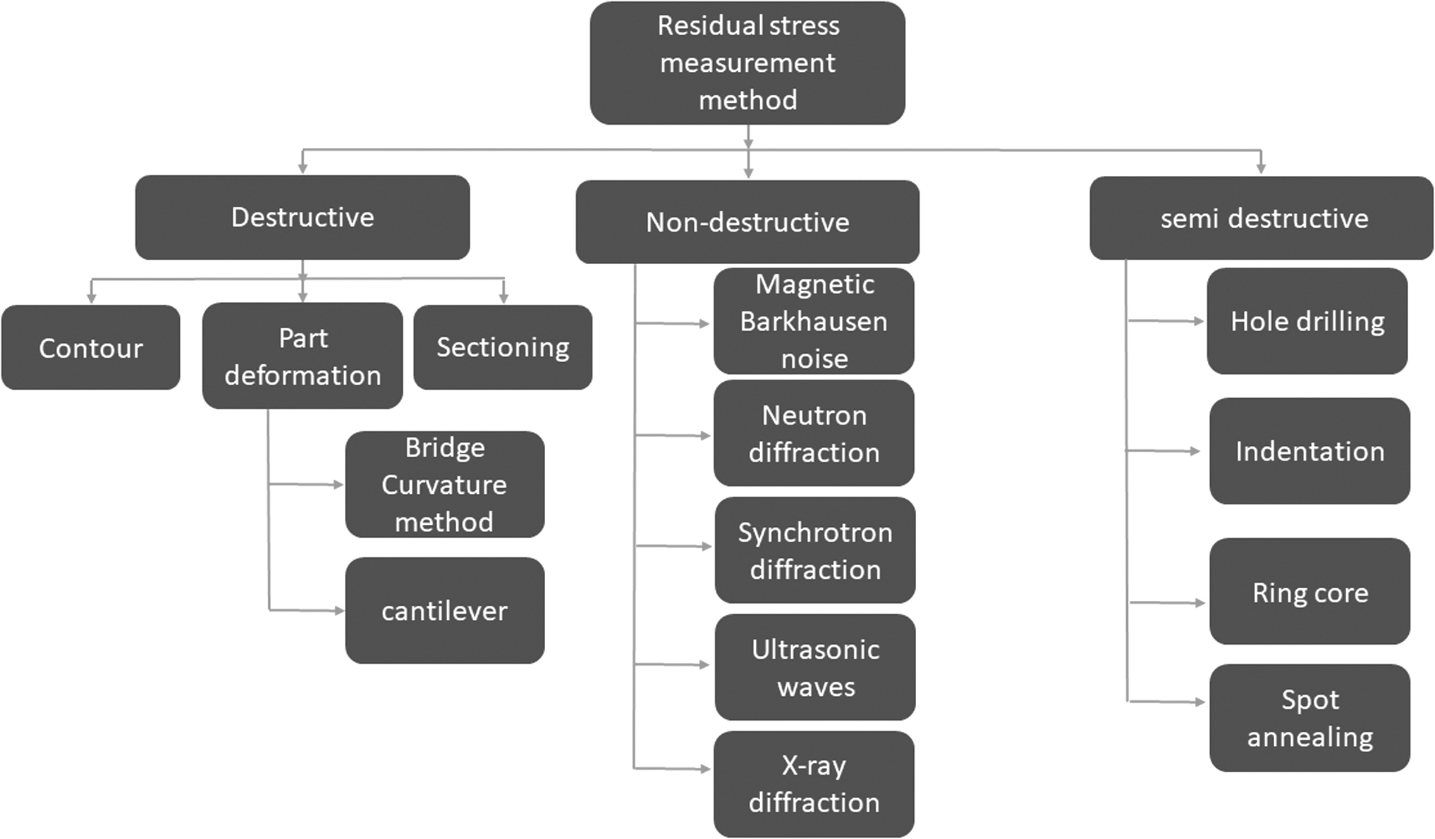
RS measurement methods
The three main categories of RS measurement techniques are nondestructive, semidestructive, and destructive. The crystal lattice tension is calculated using nondestructive techniques (NDT), such as neutron diffraction and XRD (Fig. 6). The subsequent RS is calculated using linear elastic deformation. 41
Residual stress measurement techniques.
NDT techniques can give data on various material properties: tensile modulus, fracture toughness, tensile modulus, fracture toughness, microstructure, and defects and so on. In addition to high accuracy, these techniques typically offer excellent flexibility of use and repeatability.
Destructive techniques, like sectioning, involve separating particular section of a part to lessen RS. Then, distortion is generated and the associated stresses can be resolved. To evaluate distortion behavior and then determine RS values, these methods typically require FEM tools. Compared to destructive methods, semidestructive techniques (Fig. 6) result in fewer modifications to the properties. HD is the most popular of these. To quantify stress profiles, a portion (hole) of a part is cut out, and strain gauges are then installed. In the majority of contemporary methods, DIC can be coupled to HD and give more exact details on the stress behavior. FEM simulations can be used as a complementary way to learn about RS.
Various writers43–46 correlate the findings of their work using a linear elastic model developed with FEM software. Presently, RS in AM are measured using HD and XRD because measurement with this tool is easy. Despite the excellent accuracy and reliability of both techniques, there are some drawbacks. For example, good finished surfaces are best for measurement with this technique; however, roughed surfaces will not give the results properly. 47 HD method is a destructive measurement technique; in this method, a small hole is drilled from the measuring region where RS is to be measured. In these drilled portions, strain gauges are arranged according to the test standards. Hence strain gauge calculates the associated stresses. 47 The Incremental Hole-Drilling variant of HD gives error for measuring RS surrounding the hole due to generation of the stress concentration for the plasticity effect of the material. 48
Ultrasonic wave (UW) testing utilized mechanical waves, which are movements of particles of material that require a medium to propagate. 49 The frequency of the UW has higher than 20 KHz; its use in NDT has great benefits, including excellent accuracy, great speed, and the ability to operate in a variety of environments, together with liquids. 50
RS in concern to AM
After part fabrication, a heat treatment process is conducted to homogenize the microstructure, which is the usual solution to lessen RS. When the treatment is carried out in the 600–700°C region for AM parts, RS can be reduced by up to 70%. 51 Stress transfer and microstructure homogenization are developed by annealing. In addition, a number of other characteristics, including tensile strength, ductility, and toughness, 52 can be enhanced.
Li et al. 53 claimed that preheating the powder above 570°C could eradicate RS. There is a 40% decrease of RS seen, when the operating base plate was heated to 160°C. 54 However, a preheating temperature of 250°C was used in AlSi10Mg cantilevers produced by SLM in another research by Buchbinder et al., 55 which produced no flaw or distortion. In addition, low RS was generated in these zones due to smaller thermal gradients.
According to Ali et al., 56 who used preheating temperatures between 370°C and 770°C, minimum RS was discovered during the manufacture of SLM parts at a temperature of 570°C. Compressive RS was detected in various specimens, including I beam geometries, at preheating temps of 570°C to 770°C. 57 In addition, cooling was reduced during fabrication, which led to the production of components with a high yield strength (1176 MPa).
A computational analysis of scanning path optimization in AM processes was done by Chen et al. 58 Stress distributions can be minimized using the Adaptive Level Set Adjustment approach.
The creation of Metal Matrix Nanocomposite (MMNC) materials for AM techniques is a different strategy to lessen the impact of RS. In a study by Yu et al., 59 this subject has been covered in great detail. The manufacturing of MMNC components by SLM could have a number of benefits, including increased strength and resistance to crack propagation, as nanoparticles guarantee the refinement of the powder structure and enhancement of the strength of the component.
Conclusion and Future Aspects
AM is a developing technology; however, there is great demand for RS and its elimination from AM manufactured parts. AM can manufacture complicated shapes quicker than other techniques. The fatigue life and other mechanical properties can be adversely affected by RS. During AM process in various materials, microstructure can change. RS within the material can be produced by inhomogeneous microstructure evolution and nonuniform phase transitions. In this respect, stress-relieving heat treatments can assist in producing a microstructure that is more uniform and free from stress.
This review article discussed a summary of the RS in metal AM. The effect of the suggested RS formation mechanism was discussed. The RS detection techniques and their connection to microstructure were then examined. For metal AM, the usual RS properties and its mitigation techniques were outlined and discussed.
In addition, there is an increasing need for finer control of these stresses in AM technologies: new developments like hybrid instrumentation, involving various NDT techniques, could provide more details on part abnormalities and speed up production. Under the additive manufacturing of metals—Non-destructive testing and evaluation—Defect detection in parts (ISO/ASTM—DTR 52905) initiative, a specific collection of norms for NDT of AM parts is currently being developed. Hence, this will increase our knowledge on the performance of NDT in complicated AM parts with better accuracy and repeatability.
Footnotes
Acknowledgments
The authors are grateful to the Department of chemicals and petrochemicals, ministry of chemicals and fertilizers (DCPC), Government of India, for sponsoring “Centers of Excellence” in the field of Petrochemicals.
Authors' Contributions
T.B.: Conceptualization, writing-original draft preparation, visualization, and investigation. S.M.: Reviewing and editing.
Author Disclosure Statement
The authors declare no competing interests.
Funding Information
For the research, authoring, and/or publishing of this article, the author(s) received financial support from Department of chemicals and petrochemicals, ministry of chemicals and fertilizers (DCPC), Government of India (F.No.25012/01/2020-PC-II (FTS 16020)).