
Abstract
This article presents a fabrication strategy on the structural design, optimization, additive manufacturing, and processing of metal mirror. Specifically, the study showcases the topology design of a metal mirror with diameter of 200 mm, the additive manufacturing of standard aluminum-based powder (AlSi10Mg), the high-precision single-point diamond turning process of the surface. By setting the feasible domain partition, a topology optimization model suitable for metal additive manufacturing and subsequent surface shaping was constructed, which takes into account the multi-load machining load conditions of single-point diamond turning technology and the material topology representation of standard support structures for additive manufacturing. The results demonstrate that the optimization model effectively suppresses the vibration phenomenon during single-point cutting. Furthermore, the results of the optical interferometer surface inspection confirm that the design and processing strategy for additively manufactured metal mirrors demonstrated in this study can be directly applied to infrared band reflective imaging optical systems.
Introduction
Metallic mirrors and their support systems are commonly employed in the design and optimization of reflection optical systems. 1 Such optical systems rely mainly on the reflective surfaces and coatings to fulfil their optical functions. The selection of suitable mirror bodies for reflective mirrors is quite extensive, and there is potential for achieving lightweight designs through the choice of materials and body design of the mirror. By utilizing ultra-precision single-point diamond turning technology (SPDT), submicron surface accuracy and nanometer-level surface roughness can be achieved. 2 Metallic mirrors have numerous applications in the visible-to-infrared wavelength range, as evidenced by various studies.2–4
Metal additive manufacturing, with its high degree of manufacturing freedom, integrated design, and capacity for structure–property integration,5,6 has garnered significant attention and application in the domains of optical reflection mirrors and optomechanical structures. 7 In contrast to traditional lightweight structures of metal-based reflective mirrors, metal-based additive manufacturing reflective mirrors can realize designs with high rigidity and fully enclosed structures, thanks to their layered manufacturing process.8–10 Through design optimization, functional reflective mirror components such as internal channels can be integrated into the mirror body, 11 enabling the fulfilment of specific requirements such as water-cooled reflection mirrors. An exemplary application is the off-axis three-mirror system for space imaging. By using appropriate support structures and SPDT processing, the multi-mirror component with Mirror 1 and Mirror 3 can be integrated into one common substrate.12,13 The integration of multi-mirror and support structure materials significantly reduces both installation and alignment time and the impact of thermal expansion effects of different materials on the optical system performance.2,4
Metal additive manufacturing reflectors offer great flexibility in processing and design space, allowing for the production of both classic honeycomb sandwich structures for lightweight design10,14 and optical performance device design through numerical topology optimization strategies.7–10,12,15–23 Table 1 below lists the metal additive manufacturing reflector mirror parameters and corresponding design algorithms that have been reported in the literature in recent years. From a structural design perspective, most lightweight designs for metal additive manufacturing reflectors follow the classic design paradigm, relying heavily on the empirical properties of honeycomb or rib structures. Some lightweight metal additive manufacturing reflectors are designed using self-supporting lattice structures combined with topology optimization to achieve highly rigid and lightweight mirror body structures. A novel approach is the use of gradient Voronoi cells15,24 for lightweight concept design, which, when combined with topology optimization, can achieve higher levels of lightweighting and rigidity.
Design Algorithm, Processing Materials, and Optical System Configuration of Metal-Based Additive Manufacturing Mirror
FEA, finite element analysis; RMS, root mean square.
The main objective of topology-optimized reflector designs is to minimize the overall structural compliance, with some objectives also considering the root mean square (RMS) displacement variation of the mirror surface and stiffness status. The optimization model is mainly based on load cases such as polished surface loads and the actual use under self-weight conditions for inverse optimization design of the structure.
However, from the perspective of the manufacturing process of metal mirrors, the more classical process suitable for visible and short-wave metal processing is as follows: 3D printed metal mirror—Heat treatment and aging treatment—SPDT—Modified coating using nickel alloy–SPDT—Polishing—Reflection coating and protective coating process. 25 If the mirror is required in infrared band, only one SPDT process is needed. From the above process, metal SPDT technology is the core design technology for metal-based additive manufacturing mirrors. The design algorithm for mirrors needs to focus on the machinability adapted to the SPDT process. Compared with the surface load of polishing, the removal amount of SPDT and the improper scratches during the processing have a greater impact on the mirror surface. Especially in the machining of large-aperture optical mirrors, the machinability of the designed mirror body's SPDT needs to be more closely examined.
This article presents the design algorithm and processing flow of a center-supported reflector, and proposes a structural optimization design strategy suitable for multi-load conditions in the processing of this type of reflector, based on the multi-load working conditions of SPDT. Methods section proposes a topology optimization algorithm for this type of processing, as well as a lattice filling sequence optimization design concept that considers printable manufacturing, and shows the precision transfer fixture design from the blank to the finished product to SPDT. Results and Discussions section presents the printing product and surface shape inspection results after SPDT. Conclusions and Outlook section discusses some of the key technical points that the authors believe should be focused on in future research in this direction.
Methods
To improve the structural stiffness and increase design flexibility, this study adopts metal additive manufacturing technology to produce a fully enclosed mirror for reflection, while also considering the supporting structure. On this premise, topology optimization is employed as the primary method for designing the mirror configuration, taking into account the stability of the structure during the manufacturing process and reducing the unessential postprocessing procedures. A topology optimization model is established that considers the manufacturing constraints. The design model focuses on two main issues:
Resolving the problem of structural edge flutter that arises from periodic local loads during the cutting process. Designing a mirror model that can be printed without auxiliary support to avoid the challenges associated with removing internal support and the impact of tool marks on surface accuracy after support removal.
This article proposes a multi-load topology optimization model to simulate the cutting force loads acting on different positions of the mirror surface. Multiple discrete and distributed loads that can cover the entire mirror surface are selected as input, and compliances and sensitivity fields under all loads are superimposed to obtain topology optimization results that enhance the local stiffness of the mirror, thus solving the problem of structural edge flutter during the turning process. For the designing scheme without auxiliary supports, a lattice configuration is considered to be filled inside the mirror cavity. On the one hand, the lattice can replace the auxiliary support to achieve printing without supports; and on the other hand, the lattice usually has excellent specific stiffness (although it is generally anisotropic), which can further improve the overall stiffness performance of the mirror. In addition, since the interior of the mirror body may not be a regular cavity, lattice structures that are periodically or circularly distributed are difficult to connect with the inner wall of the cavity or maintain the integrity of the lattice. Therefore, local adaptive size adjustment of the lattice is also required.
Based on the above, shell and lattice are proposed as the basic design element of the mirror. The shell is designed using a multi-load topology optimization model, while the lattice has a predetermined configuration, and is filled into the shell through adaptive lattice size adjustment.
During the shell optimization, the lattice is equivalent to a uniformly weak material, and the performance of this material is only estimated through the homogenization of the standard lattice. To fully utilize the stiffness performance of the lattice, it is usually required that the boundary of the lattice has a certain stiffness support capability. In this design, to ensure this condition as much as possible, the equivalent weak material inside the shell (the space reserved for the lattice) changes synchronously with the shell in the optimization process. After the shell optimization is completed, the exposed lattice will be closed by extra shell. Figure 1shows the design process of this approach.
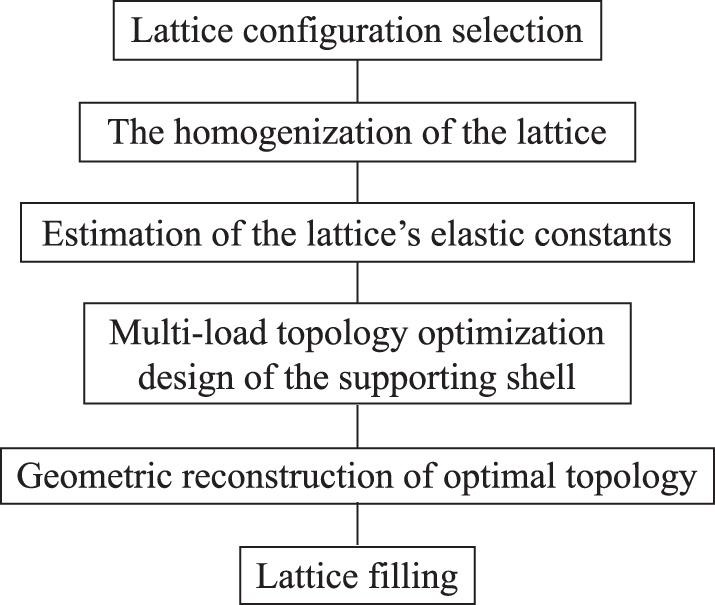
Design flow chart.
Selection of lattice structure and performance estimation
Selection of the lattice needs to fulfil both the criterion of providing sufficient vertical stiffness and enabling printing without support. The angle at which the struts are printed is a critical factor in achieving unsupported printing, with a longitudinal extension angle of the material's outer contour typically required to be greater than 45°. Therefore, in this study, the lattice structure shown in Figure 2a was selected as the filling structure of the reflector cavity. The single lattice is composed of eight straight rods with circular cross-sections, having a cross-sectional radius of ∼0.3 mm and a longitudinal extension angle of about 48°. The volume ratio of the single-cell entity to the cubic region it occupies is 0.178.
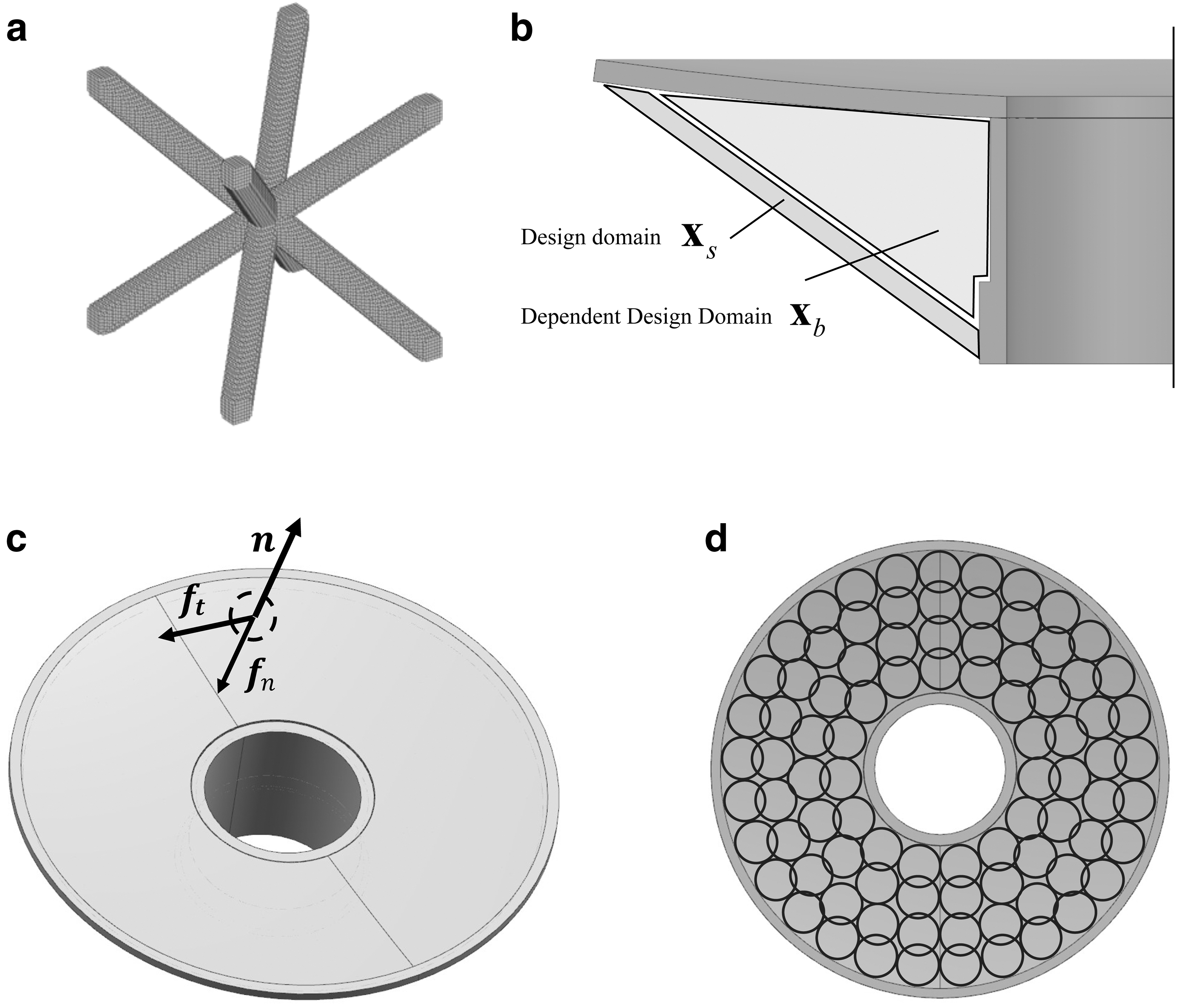
Schematic illustration optimization model
To reduce the computational complexity of the shell's topology optimization, it is necessary to equate the lattice with a homogeneous material. Conventional methods of equivalence include the Representative Volume Element method
26
and the homogenization method. Due to its more rigorous mathematical derivation, this article adopts the homogenization method to equate the lattice. Refer to standard material properties of aluminum–magnesium alloy, the material used (aluminum alloy) has an elastic modulus
Which,
To simplify the calculations, we further equate it to an isotropic material. For the cubic lattice, we adopt the Voigt–Reuss–Hill approximation method to calculate the equivalent elastic modulus E and Poisson's ratio
Herein, shear modulus and bulk modulus under Hill averaging are represented by G and B, respectively. Their expressions are given as follows:
Whereas GV and BV are shear modulus and bulk modulus under Voigt averaging, GR and BR are shear modulus and bulk modulus under Reuss averaging, and their expressions are given as follows, respectively:
Upon substitution of numerical values, the elastic modulus and Poisson's ratio are obtained as 2.082 GPa and 0.34, respectively.
Multi-load model of supporting shell considering manufacturing conditions
Taking into account both engineering experience and actual cutting loads, this article proposes an equivalent static multi-load optimization model that approximates the cutting load during turning. The model considers the pressure
Multi-load enclosed shell and lattice sequence topology optimization model
Topological optimization is implemented using the solid isotropic material with penalization (SIMP) material model, which achieves material evolution through continuous changes in the relative density of elements. The expression for the Young's modulus of the material is shown below:
Here, E0 and
As mentioned earlier, the lattices are approximated as homogeneous isotropic materials and are not optimized as independent design variables, but instead depend on changes in the shell design variables. As shown in Figure 2b, assuming that the shell material in a certain region is removed or introduced during the optimization process, all equivalent lattice materials along the optical axis direction are synchronously removed or introduced. Therefore, there are two types of design variables in this optimization model: the elements' relative density
It should be noted that the synchronous increase or decrease of the shell and lattice equivalent materials along the optical axis direction is similar to the drawing constraint in topology optimization, which can also ensure the manufacturability of the structure. The SIMP model in discrete form is as follows:
where
In addition, to ensure that the mirror has sufficient stiffness for cutting, a nondesign domain with a thickness of 8 mm was added, and all loads were applied to the nondesign domain. Based on the above, we established the following topology optimization model:

The variables in the Equation (11) are defined as follows: c represents the overall structural compliance, N denotes the number of loads applied to the mirror surface, ci and wi are the compliance and weight under the i-th load, and in this article, all weight values are set to 1.
After the model is established, the implicit representation of the multiple loads applied on the surface and the calculation of sensitivity are relativity easy to impose. This part of the content one can refer to previously published relevant articles from our research group.31–35
The optimal topology is depicted in Figure 3a. It can be observed that several droplet-like holes are presented on the shell. Subsequently, we performed geometric reconstruction of the result through 3D modeling software. The droplet-shaped holes were uniformly drawn as orifices consisting of two circular arcs with radii of 6 and 9 mm, respectively, and two-line segments with lengths of 40 mm, thereby resulting in a total of 14 lightweight holes on the shell. To ensure adequate lattice support, sidewalls with thicknesses consistent with the shell were added along the axial direction of the holes, completely sealing off the lattice. Additionally, in view of the fact that additive manufacturing tends to leave a small amount of metal powder inside the cavity, thereby affecting the total mass and center of gravity stability of the reflective mirror, 14 circular powder discharge holes with a radius of 2.5 mm were incorporated on the shell. The details of the model are illustrated in Figure 3b.

Optimized Results and its reconstructed internal lattice structure.
Internal lattice distribution
To satisfy the spatial characteristics of circular symmetry and the stability of rod-end connections, the sizes of lattices were locally adjusted based on the shape of the cavity. Along the radial direction, there are primarily two forms of distribution: the distribution of rods between the central hole and the lightweight holes is relatively random, mainly to ensure connectivity with the inner wall, while the lattice distribution along the circumferential direction of the lightweight holes is relatively uniform, and the lattices' size gradually increases with the radius. The rods are primarily connected to the sidewalls of the lightweight holes. The final configuration is illustrated in Figure 3c and d.
Fabrication and processing strategy of the metal mirror
After completing the model processing, the metal mirror fabrication strategy and treatment flow in this study are presented as follows:
The mirror surface is precision detected using 3D scanning technology. The 3D scanning data are used to assess the accuracy of the mirror surface. The 3D scanning data are also used to prepare data for subsequent precision machining. The mirror surface is precision machined using a precision surface machining process. The mirror is subjected to thermal stress aging treatment to improve its mechanical stability. The mirror surface is shaped to high precision using single-point diamond turning (SPDT)
 Step 1: 3D printing fabrication Step 2: Mirror surface precision detection
Step 3: Precision machining
Step 4: Thermal stress aging treatment
Step 5: Single diamond turning
The additive manufacturing process utilized an optimized and reconstructed structure with a self-supporting metal lattice design internally. Due to the limited removal amount of diamond single-point turning technology, surface inspection was conducted on the formed samples after additive manufacturing to ensure machining reliability and efficiency. Based on the surface inspection results, targeted precision turning was carried out to remove significant surface irregularities on the optical surfaces. Subsequently, after thermal stress aging treatment, the formed samples were mounted on a SPDT using the same tooling as utilized for precision turning, and high-precision reflective surface were turned in one pass.
Results and Discussions
Reflection mirror printing and mirror surface preparation
The reflection mirror fabricated in this study was produced using DLM-280, manufactured by DediBot Co., Ltd. The self-supporting lattice structure was selected for the internal cavities of the material, and removal of the overall support only required removing the external shell support. The printing direction of the mirror is parallel to the optical axis, and the mirror surface is located on the top layer. The layer thickness is chosen to be 40 μm, the base plate heating temperature is 120°C, the laser power is 300 W, and the shield gas is argon. The performance and parameter list of the selected printer are shown in Table 2. The chemical composition of the AlSi10Mg material used for fabrication is presented in Table 3, which indicates that the aluminum alloy powder utilized in this study is the most common standard metal-based additive manufacturing material.
Specification Parameter of Metal Additive Manufacturing
Chemical Composition of Metal Powder
After preparing the mirror substrate, a conventional vacuum furnace was utilized. The heat treatment involved heating the substrate to 260°C for 2 h. The resulting metal mirror component had a density of 2.65 g/cm3, which was calculated to be 99.25% of the theoretical density of 2.67 g/cm3. 36 The mass of the mirror was 790 g, and the surface density was calculated to be 22.8086 kg/m2, based on an effective aperture diameter of 210 mm. In terms of densification in aluminum-based metal additive manufacturing, the printing process used in this study was conventional. With regard to mirror surface preparation, the density influenced the porosity, which in turn impacted the quality of surface single-point cutting. Achieving a higher quality surface would require improved densification through enhanced heat treatment and printing processes. Current research in metal printing technology indicates that aluminum–silicon-based metal additive manufacturing can attain a relative density of up to 99.9%.37,38 Figure 4 illustrates the contour and effect of the formed shape postprinting. The precision machining step employed in this study removed ∼100 μm, with the effect and surface shape after diamond cutting demonstrated in Figure 5.

3D printed mirror and precision detection scan results.

SPDT results.
The SPDT cutting process utilized a slow tool servo strategy, with the positioning reference for the clamp and precision machining being the same. This allowed for the unification of the positioning and processing references for the SPDT operation. The primary processing parameters employed in the single-point diamond cutting process are presented in Table 4.
Parameters of Single-Point Diamond Turning Processing
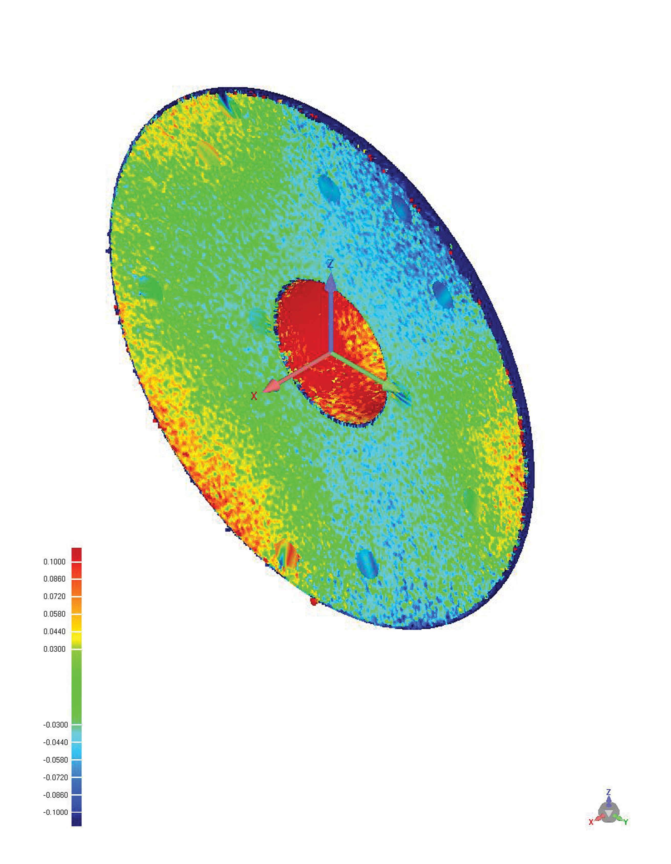
The mirror surface accuracy was assessed using a 4D interferometer and a collimator to measure the printed mirror. The obtained inspection results, presented in Figure 6 reveal that the surface accuracy RMS was ∼0.152λ, and the peak to valley was 0.743λ (λ = 632.8 nm). In general, the physical diameter of the mirror is usually larger than the effective diameter. Therefore, the outer edge and the inner edge exceeding the effective diameter are not considered as effective optical mirrors during the detection process. It can be seen that, except for a few red areas on the outside, the overall surface shape consistency is good. The surface inspection results indicate that the metal 3D printed mirror, produced through SPDT of one step, can be utilized directly for imaging applications in the long-wave and even mid-wave spectral range spectral range (

Results of 4D Interferometer surface testing.
Discussion—impact of design on single-point cutting performance
The core process for producing metal additive manufactured mirrors is metal SPDT, which achieves optical-grade reflective metal surface. This article's main contribution is proposing a method to enhance diamond turning performance through a structural design optimization algorithm. From the perspective of SPDT performance, the proposed algorithm simulates the load of diamond turning and optimizes the structural support to provide sufficient structural rigidity to achieve single-pass cutting efficiency.
To further demonstrate the effectiveness of the algorithm, the authors provide another mirror that was designed and manufactured earlier using an almost identical process. However, there are two key differences in the design model: (1) uniform pressure is applied to the mirror surface, and (2) the lattice is not considered in the model. The calculation results are shown in Figure 7a and b.
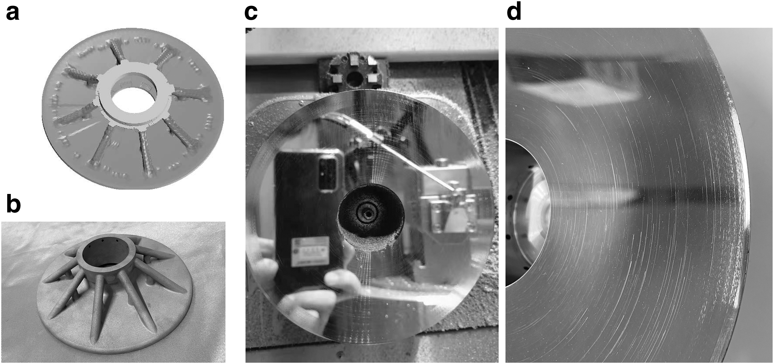
Optimized structure of uniformly distributed load.
During the SPDT process, a serious problem occurred: the edge of the mirror vibrated when a single-point diamond was used to turn it, resulting in scratch defects. These defects are clearly visible in Figure 7c and d. This defect rendered the mirror unfit for use, so it was not further detected by the interferometer. The insufficient edge stiffness of the mirror caused this problem. In this article, a multi-load model is used to address this issue, and the results show that this improvement is effective. The lattice is used primarily to achieve unsupported printing and further improve manufacturing efficiency.
Conclusions and Outlook
Based on the wide-ranging design and manufacturing freedom of aluminum-based metal mirrors enabled by additive manufacturing, and their excellent machinability, they have become increasingly important in the design of aerospace and aviation products, particularly rapid optical devices. The single-point diamond turning (SPDT) processing of 3D printing metal substrates is easier compared with traditional substrate materials such as SiC 39 or microcrystalline. 40 This is because the metal substrates have a smoother surface finish and a more uniform grain structure, which makes them easier to machine. Additionally, the cutting time of SPDT is also greatly shortened for metal substrates. As a result, single-turned cutting metal-based additive manufacturing mirrors can significantly reduce the overall time from raw material sintering, structural forming, to roughing and fine machining at the optical level. This article proposes a topology optimization design model for the single-point cutting of multi-load structures, which is a key process for this type of product, and provides results from various stages of additive manufacturing, machining, and testing.
Starting from standard aluminum powder, a good reflective mirror surface was obtained through a single-point diamond cutting process. We believe that the metal-based additive mirror design completed through the algorithm and thinking of multi-load working conditions provides the structural rigidity required for single-point diamond cutting.
From the perspective of optical processing, the surface shape of an additively manufactured mirror is mainly affected by the size of the porosity of the additive, and the waviness formed is mainly affected by the structural stiffness design of the substrate and the SPDT processing strategy. The edge scratches discussed in the second part of this article are mainly caused by edge resonance due to insufficient structural stiffness. Therefore, material density, material properties, and the microscopic defects of the printed material from printing all have a crucial impact on the final performance of a 3D printed metal mirror.
However, based on the author's experience in low-density processing and structural design,41,42 it can be seen that in cases of lower density and relatively fewer defects, surface scratches can be avoided and imaging reflection mirrors suitable for mid-wave infrared can be achieved through the use of design algorithms. We believe that with better heat treatment and the use of aluminum-based materials with smaller printed defects, it is possible to achieve more reasonable and accuracy surface for SPDT through the use of design algorithms at higher densities. Therefore, it is necessary to further focus on developing surface precision optimization algorithms suitable for SPDT.
It is worth noting that the method proposed in this study does not utilize the shell+ lattice coupling optimization approach. There are two main reasons for this: first, such structures are usually solved using multiscale optimization algorithms, which are complex, unstable, and time-consuming, making it difficult to obtain the optimized design quickly. Second, nonperiodic random lattice structures are difficult to use uniformization methods to achieve performance equivalence, making it challenging to reduce computational time. As the focus of this article is to provide a feasible design solution, rather than to explore optimization algorithms, we have made an approximation to this issue.
The algorithm presented in this article emphasizes improving the rigidity of the SPDT process while considering the lightweighting requirements. The multi-load topology optimization model is automatically generated by algorithms, and the design time is mainly limited by the calculation of the topology optimization model. The regularization and reconstruction of the optimized structure are also time-consuming. Therefore, there is still room for improvement in terms of surface density. Future work will focus on enhancing the mirror's overall density to better utilize the design freedom advantages of metal additive manufacturing.
Footnotes
Authors' Contributions
Q.W.: conceptualization, methodology, formal analysis, fabrication, and writing—original draft; C.W.: methodology, formal analysis, investigation, and writing—review and editing; Y.C.: methodology and optimization; L.C.: methodology and investigation; C.L: fabrication, SPDT processing, and investigation; W.N: investigation, fabrication, and precision machining; J.Z: 4D Interferometer surface testing; Z.Z: conceptualization, fabrication, SPDT processing, and writing—review and editing; L.Z.: conceptualization, funding acquisition, writing—review and editing, and project administration.
Data Availability Statement
The numerical model data that support the findings of this study are available from the corresponding authors upon reasonable request.
Author Disclosure Statement
No competing financial interests exist.
Funding Information
This research was funded by the National Natural Science Foundation of China (No. 51675506) and the National Key Research and Development Program of China (No. 2018YFF01011503).