
Abstract
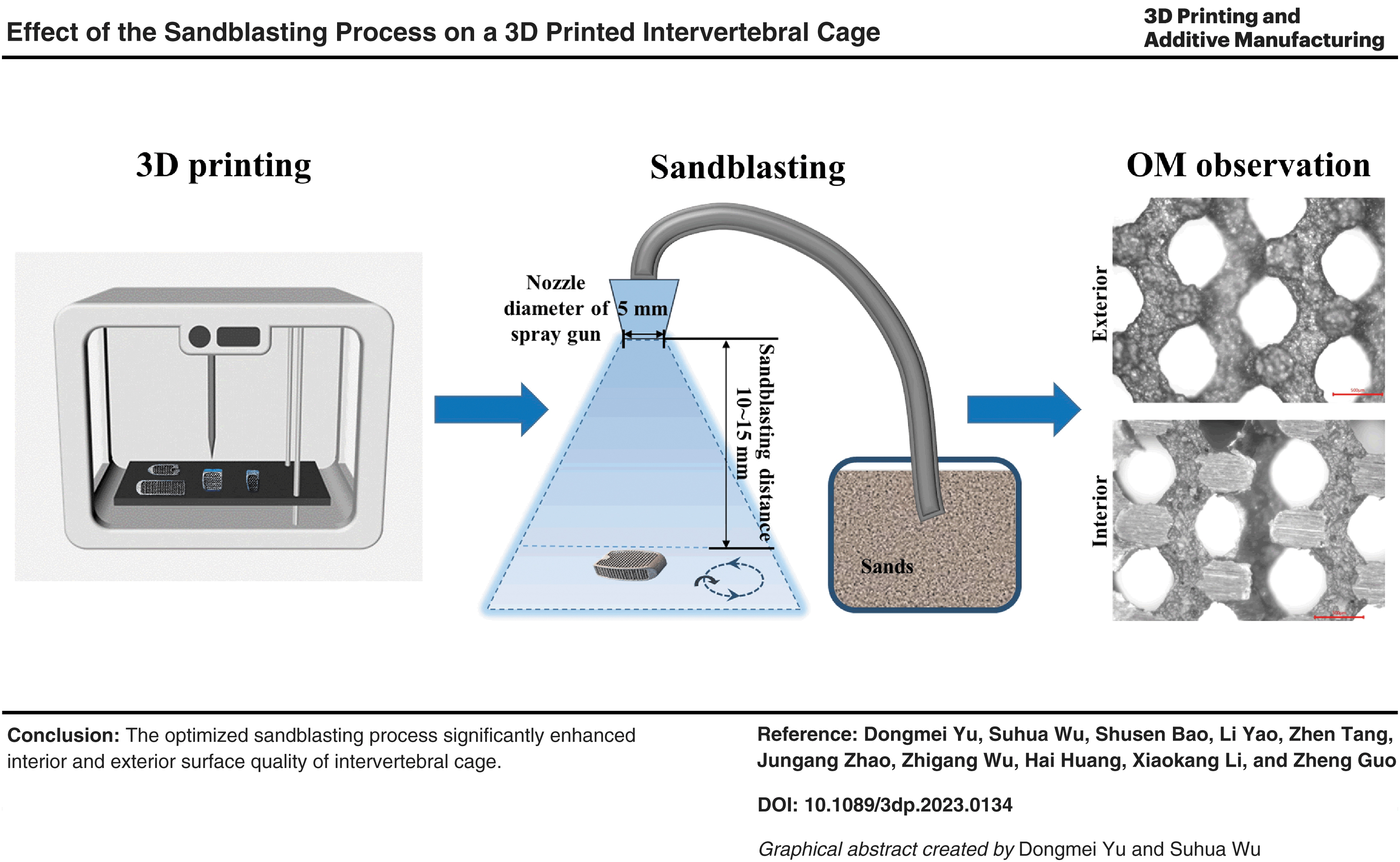
To meet the growing requirement of spinal interbody fusion caused by trauma and disease, 3D printed porous titanium alloy scaffolds were applied as intervertebral cages to achieve structural reconstruction of bone defects. However, the biological inert of the titanium alloy hindered firm bonding between the bone and porous scaffold. Surface roughness that resulted from sandblasting treatment with alumina sand grains could endow the titanium alloy scaffold with bioactivity. Minimum and maximum-type cervical and posterior lumbar cages were used to optimize the sandblasting process, achieving an adequate and uniform sandblasting effect. The optimized sandblasting process parameters were as follows: alumina sand grains of 100 mesh, sandblasting distance of 10 cm, sandblasting pressure of 0.4–0.5 MPa, and sandblasting time of 15–20 s.
Highlights
3Dprinted porous titanium alloy scaffolds were applied as cervical and posterior lumbar cages.
Sandblasting treatment with alumina sand grains was used to improve the intervertebral cage surface.
The optimized sandblasting process parameters were as follows: sand grains of 100 mesh, sandblasting distance of 10 cm, sandblasting pressure of 0.4–0.5 MPa, and sandblasting time of 15–20 s.
Introduction
Spinal interbody fusion is a crucial surgical operation for spine fusion treatment of spine disorder, deformity, and instability, as well as degenerative diseases,1,2 in which a cage is necessarily inserted between the spinal vertebrae, contributing to indirect neurologic decompression, correction of spinal alignment, anterior column stability, and increased fusion rate. 3
Currently, autogenous bone grafting is accompanied by postsurgical pain, lack of donor, and donor complications, while allograft and xenograft incur immune response complications and risk of disease transmission.4,5 These notable drawbacks prompted development of novel cage substitute materials and process technology for intervertebral fusion. The entire osseointegration between the cage surface and vertebral end plates determines the long-term success of interbody fusion and thus optimization of interbody cage materials and designs is important for fusion efficacy. 3
Titanium and its alloys, because of their high specific strength (high strength and low density) and excellent biocompatibility, have been applied as biomedical load-bearing implant materials for bone defect reconstruction in orthopedics.6–8 However, due to high elastic modulus mismatch with that of natural bone tissue, solid titanium alloys were liable to generate stress shielding, which finally caused fracture failure in clinical practice. 9
Fortunately, bulk porosity intelligently introduced into high-modulus interbody titanium alloys can effectively modulate compressive moduli to physiologic ranges between that of cortical and cancellous bone for even load sharing and transfer. 3 Porous titanium alloy scaffolds fabricated by selective laser melting (SLM) 3D printing technology, a metal additive manufacturing process, 10 could reduce the elastic modulus of the implant by regulating aperture parameters, thus eliminating the stress-shielding effect and preventing it from loosening. 11
Simultaneously, 3D printed porous titanium alloy scaffolds could ensure the clinical requirement of mechanical strength.12,13 Furthermore, computer-aided design based on reverse engineering techniques14,15 and 3D printing technology have the remarkable advantage of patient-specific individualized restoration to closely realize structural reconstruction of original host bone defects.6,16 A patient-specific bone substitute achieved macroarchitecture (the overall outer shape), inner microarchitecture (e.g., pore size, shape, and porosity), and surface nanoarchitecture. 17
The 3D printed porous titanium alloy scaffold provided an open and interconnected porous structure conducive to cell migration and bone ingrowth by mimicking the porosity network of native bone and achieving sturdy mechanical locking between the porous titanium scaffold and bone tissue.3,13 3D printed Ti6Al4V surfaces could promote early osseointegration compared with the conventional machined surface, but the osseointegration difference diminished at later stages. 7
Hitherto, 3D printing is a booming technology for orthopedic implant fabrication. A reliable fixation interface between the bone and implant is required during bone healing. Therefore, biologically inert titanium scaffolds were endowed with bioactivity to further promote the cell adhesion rate and enhance bonding of the implant and bone tissue.
Bioactivity on implantable metallic materials to facilitate osseointegration by increasing adhesion between bone tissue and material was usually achieved by physical and chemical activation, mimicking the original structure and function of the host bone and thus prolonging its service life.18,19 Compared with the chemically activated implant surface, physical surface activation, such as surface roughness, has garnered more attention. 20
Surface roughness realized by the sandblasting treatment could improve surface wettability, cell attachment, and mechanical properties on the surface layer of titanium implants,21,22 maximizing osteoconductivity and minimizing the fibrotic response without significant mechanical alteration. 3 Moreover, sandblasting, as an easy and low-cost technique, could not only promote surface strength due to plastic deformation of a subsurface layer, 20 but also attain the removal of unmelted powder particles sintered to a 3D printed porous titanium alloy scaffold for surface quality enhancement through postpolishing or finishing (e.g., tumbling or sandblasting).23–25
In this work, porous and solid titanium alloy intervertebral (such as cervical and lumbar) cages were designed using reverse engineering techniques and fabricated by SLM, in which a solid frame was inserted on the outer edge of the porous titanium alloy for better mechanical properties and ease of use. To improve fusion performance, the intervertebral cages were subjected to sandblasting treatment and finally the optimized sandblasting process was determined.
Materials and Methods
The waiver statement of IRB was determined. All the intervertebral cages in this work are in the phase of design and fabrication, not involved in biological experiments.
Materials
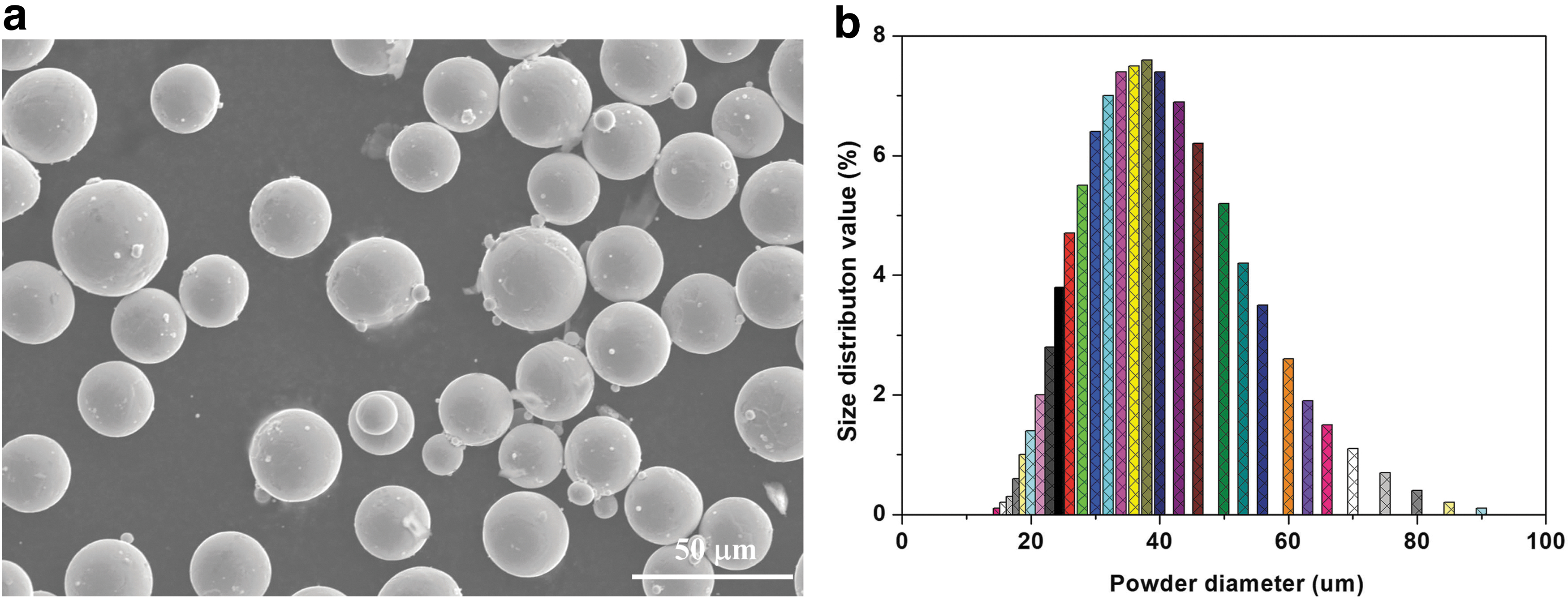
The as-received commercial Ti6Al4V powder (Ticona, Canada) exhibits a near-spherical shape with an average particle size of 28.6 μm, observed under a scanning electron microscope (SEM; SU6600, Japan) (Fig. 1a), and the particle diameter versus size distribution value was detected using a particle size analyzer (Litesizer500, Austria) (Fig. 1b). Industrial alumina (Al2O3) sand grains and white corundum, with particle size of 45–100 mesh (maximum outer mean diameter 0.25–0.56 mm), as sandblasting raw materials, were visualized under an optical microscope (OM; China) (Fig. 2).
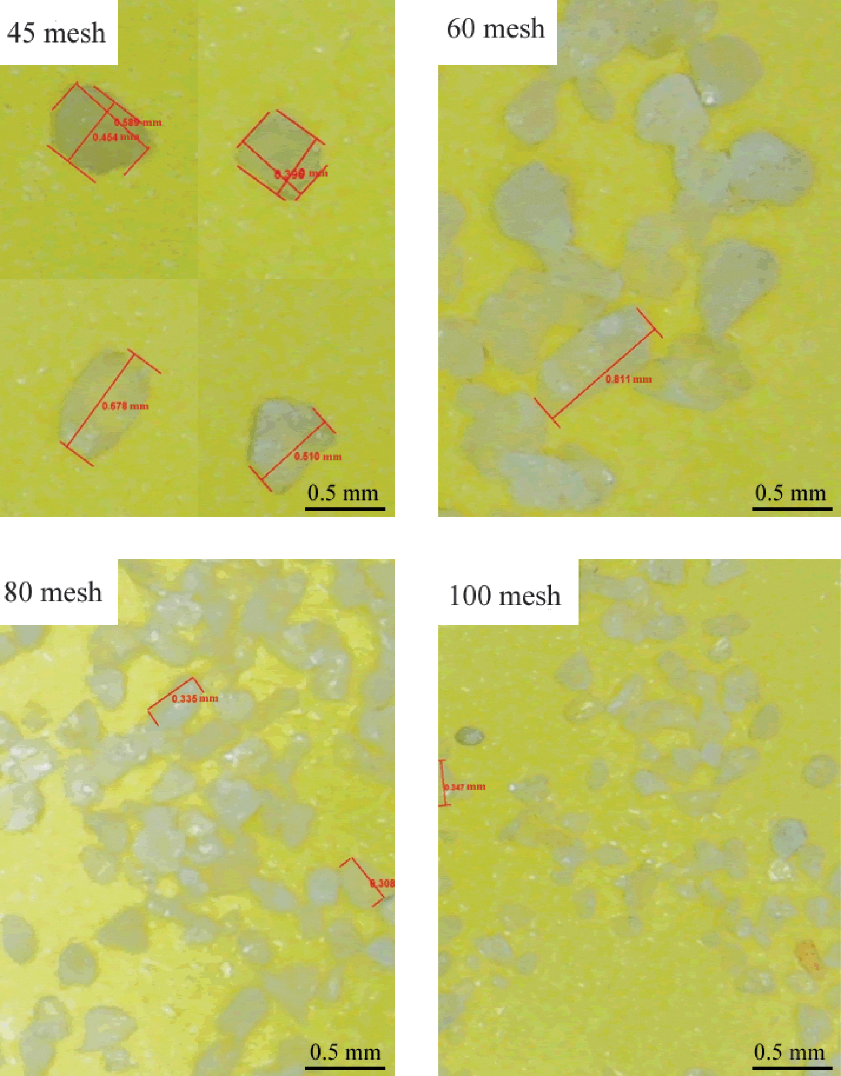
OM images and particle sizes of alumina sand grains of 45, 60, 80, and 100 mesh. OM, optical microscope.
Intervertebral cage fabricated by SLM
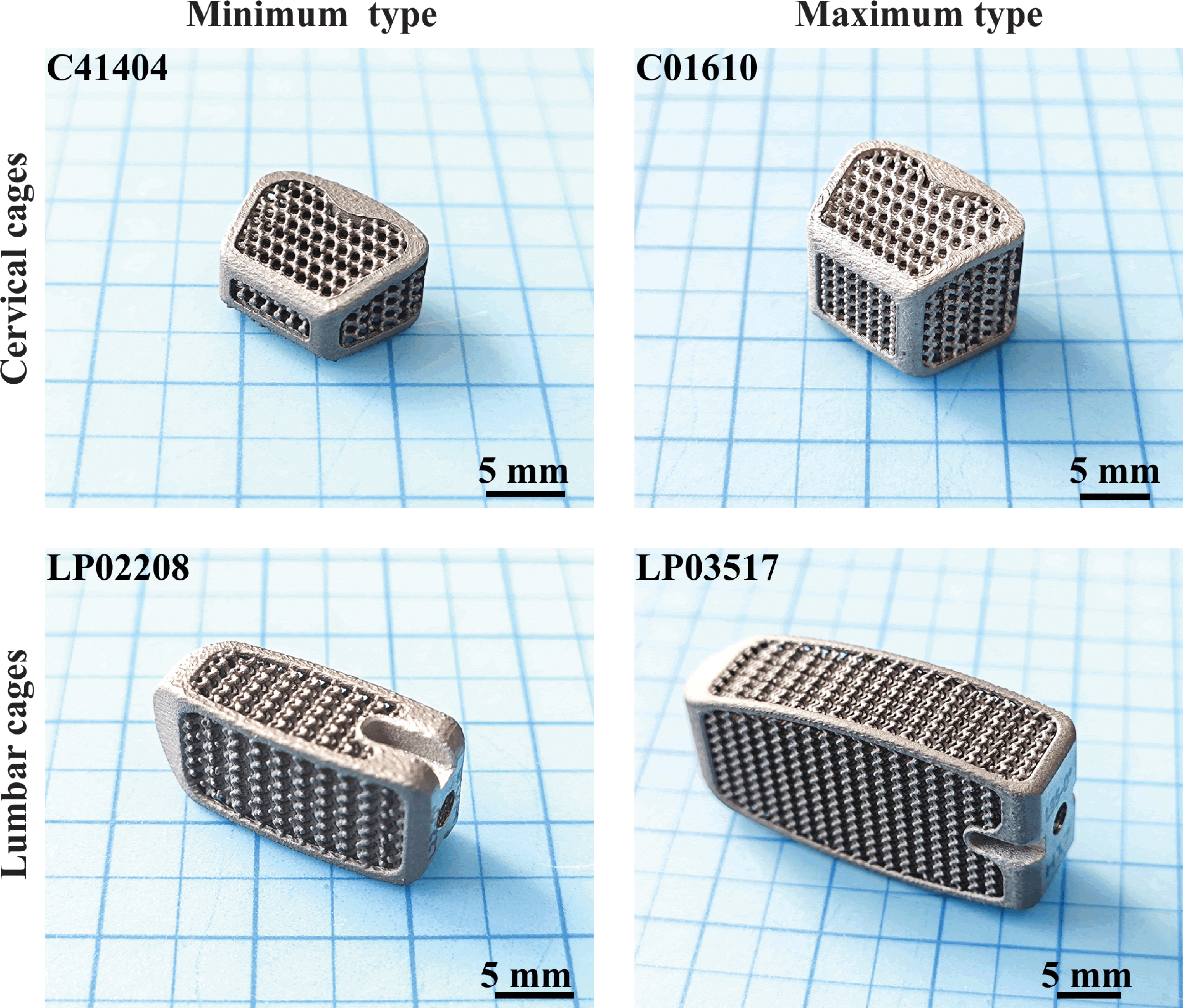
3D printed Ti6Al4V intervertebral cages were fabricated using an SLM machine (BLT-S310; Bright Laser Technologies Co., Ltd., China) with a fiber laser. C41404 and C01610 as minimum and maximum-type cervical cages, respectively, as well as LP02208 and LP03517 as minimum and maximum-type lumbar posterior lumbar cages, respectively, were laminated and manufactured with a diamond porous unit (pore size: 600 ± 50 μm; average filament diameter: 400 ± 50 μm; and porosity: >60%). Types and corresponding dimensions of intervertebral cages are listed in Table 1.
Types and Corresponding Dimensions of Intervertebral Cages
The naming of cervical cages was based on parameters; for example, C41404 consists of the acronym “C” for cervical cage as the classification code, 4° inclination of the upper surface, 14 mm length, and 4 mm height, while LP03517 exemplifies the naming of posterior lumbar cages more suitable for posterior implantation, consisting of the acronym “LP” for posterior lumbar cage as the classification code, 0° inclination of the upper surface, 35 mm length, and 17 mm height. Process parameters of selective laser melting molding are as follows: laser power of 50–350 W and scanning speed 800–1800 mm/s.
Sandblasting process
The surface sandblasting treatment was performed using a sandblasting machine equipped with a spray gun (9070A; Xi'an quailed Tongchuang Machinery Co., Ltd., China), which exploited alumina (Al2O3) sand grains with irregular shape at high pressure to achieve sandblasting on the 3D printed porous intervertebral cage surface. The sandblasting treatment of the 3D printed intervertebral cage was executed with sand grains in the dry state, in which mobility of sand grains during the sandblasting treatment was ensured, preventing wet sand grains from agglomeration and further intervention in the homogeneity of the sandblasting effect.
During the sandblasting treatment, the intervertebral cages were rotated horizontally on a rotating device, as diagrammed in the Graphical Abstract section. Optimization of sandblasting process parameters, including the particle size of sand grains and sandblasting distance, pressure, and time, for intervertebral cages was investigated.
Particle size of sand grains
Given the pore size of 3D printed porous intervertebral cages and particle size of sand grains, the sand grains of 45, 60, 80, and 100 mesh (corresponding to 0.355, 0.250, 0.180, and 0.150 mm) were selected to conduct the sandblasting process on 3D printed porous C41404 and LP02208 intervertebral cages as minimum-type cervical and posterior lumbar cages, respectively.
Sandblasting distance
Sandblasting distances of 5, 10, and 15 cm were employed on the 3D printed porous LP03517 intervertebral cage (maximum-type posterior lumbar cage) at sandblasting pressure of 0.3 MPa and sandblasting time of 20 s.
Sandblasting pressure and time
Sandblasting pressure levels of 0.4, 0.5, and 0.6 MPa were applied on the 3D printed porous C01610 intervertebral cage (maximum-type cervical cage). Sandblasting times of 5, 10, 15, and 20 s were executed on the 3D printed porous C01610 intervertebral cage (maximum-type cervical cage).
Results and Discussion
3D printed intervertebral cage
3D printed intervertebral cages, including the maximum and minimum-type cervical and posterior lumbar cages, are exhibited (Fig. 3). The structural design of intervertebral cages combined solid truss with primary porous structure parts.
3D printed intervertebral cages.
On the one hand, solid truss strengthens the bearing capacity of intervertebral cages to satisfy clinical service demand. On the other hand, primary porous structured parts could eliminate stress shielding through optimized porosity and pore size and provide space for bone ingrowth. The intervertebral cages had a diamond porous unit with pore size of 600 ± 50 μm and average filament diameter of 400 ± 50 μm, along with porosity exceeding 60%. It is noted that pore geometry is associated with load-bearing behavior. 26
Diamond pores are preferred compared with cubic pores that are detrimental to interconnectivity on account of edge-to-face, edge-to-edge, corner-to-face, or corner-to-edge porous connections. 27 Pore interconnectivity in intervertebral cages essentially contributes to cell migration and blood/marrow infiltration from the surface to the pore void space, promoting new bone formation, along with maximizing nutrient diffusion and exchange for osteogenic differentiation. 3
Sandblasting process parameter optimization for intervertebral cages
To achieve overall sandblasting treatment of intervertebral cages, the sand grains with small enough particle size are allowed to successfully pass through pores of cervical and posterior lumbar cages, especially minimum-typed intervertebral cages. Therefore, the minimum-type cervical and posterior lumbar cages were selected to filter the particle size of sand grains.
However, the sandblasting distance determined the effective sandblasting range, which was crucial for intervertebral cages subjected to effective sandblasting treatment, while sandblasting pressure and time only influenced the sandblasting degree, including moderate, excessive, and insufficient sandblasting effects. Among the intervertebral cages, posterior lumbar cages with similar shape as less-demanded thoracic cages clinically, had a lager size and volume than cervical cages.
As a result, the posterior lumbar cage, especially the maximum-type one, was applied to optimize the sandblasting distance so that these three types of intervertebral cages with different parameters were successfully subjected to sandblasting treatment. For sandblasting pressure and time optimization, the cervical cage with higher camber than thoracic and posterior lumbar cages, particularly the maximum-type one, was used to evaluate the sandblasting degree of uniformity and adequacy, in which the curved surface of intervertebral cages was not liable to achieve adequate and uniform sandblasting effects due to camber shielding.
Selection of particle size of sand grains
Particle size of sand grains was selected by sieves with different mesh sizes. Sieves with different mesh sizes and corresponding pore diameter were used (Supplementary Fig. S1a), and the maximum outer diameter of alumina sand grains filtered by different mesh sieves was used (Supplementary Fig. S1b). Given the intervertebral cages with diamond pores of 600 ± 50 μm, the particle size of the alumina sand grain is much less than the diamond pore size of intervertebral cages to allow the sand grain to pass through the diamond pores of cages. Of note, alumina sand grains are of irregular shape.
Statistically, the maximum outer diameter of the sand grain, especially its upper value, needs to be less than the diamond pore size of intervertebral cages for sandblasting. However, alumina sand grains of 45 and 60 mesh are excluded, owing to the upper values of their maximum outer diameter exceeding the diamond pore size of intervertebral cages. Therefore, sand grains of 80 and 100 mesh are selected to successfully conduct sandblasting for intervertebral cages with a diamond pore size of 600 ± 50 μm.
The minimum-type cervical (C41404) and lumbar (LP02208) cages are sandblasted with sand grains of 80 and 100 mesh at sandblasting pressure of 0.4 MPa, sandblasting distance of 10 cm, and sandblasting time of 20 s. Triple independent replications are performed for each type of intervertebral cage, and the sandblasting effect with sand grains of different mesh sizes on intervertebral cages is summarized in Table 2.
Sandblasting Effect of Sand Grains of Different Mesh Sizes on Intervertebral Cages
Unfortunately, the C41404-type cervical cage sandblasted with sand grains of 80 mesh led to pore blocking (Fig. 4), indicating that sand grains of 80 mesh were not suitable for sandblasting treatment of intervertebral cages with diamond pore of 600 ± 50 μm. Based on the sandblasting effect on intervertebral cages mentioned above (Table 2), sand grains of 100 mesh, superior to those of 80 mesh, were finally applied in the sandblasting treatment in this article.

Pore blocking of the C41404-type cervical cage sandblasted with sand grains of 80 mesh. Red arrow indicates pore-blocked sand grain.
Sandblasting distance optimization
Effects of sandblasting distances of 5, 10, and 20 cm were detected on the maximum-type posterior lumbar cage (LP03517, the thickest intervertebral cage among cervical, thoracic, and posterior lumbar cages) at sandblasting pressure of 0.3 MPa and sandblasting time of 20 s. Effects of sandblasting distance on intervertebral cages were observed in partition zones illustrated in the schematic diagram (Supplementary Fig. S2) and summarized in Table 3.
Effect of Sandblasting Distance on Cage
It clarified that the strut diameter of the sandblasted cage reduced significantly (Table 3) and the effective sandblasting range was too narrow to completely cover the entire maximum-type intervertebral cage at a sandblasting distance of 5 cm compared with others. Unfortunately, defects such as unmolten or partially molten particles and balling remained on strut at a sandblasting distance of 20 cm (some defects are marked in yellow dashed circles in Fig. 5). The above results revealed insufficient and excessive sandblasting treatment on cages at sandblasting distances of 5 and 20 cm, respectively.
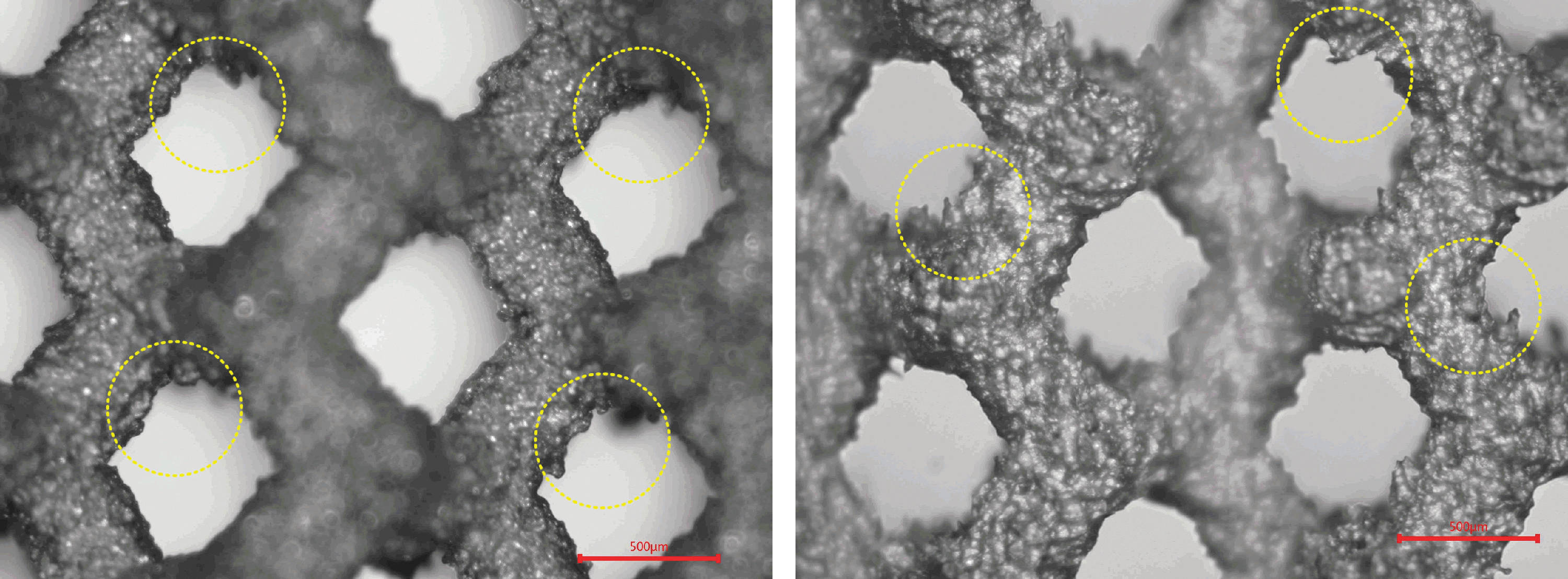
OM images of the lateral surface of the LP03517 cage at a sandblasting distance of 20 cm. Yellow circles indicate defects such as unmolten or partially molten particles and balling remained on strut.
Such defects on sandblasted cage struts were adequately removed and the cage strut diameter after sandblasting nearly showed no prominent alteration at a sandblasting distance of 10 cm (Fig. 6). However, obvious pore deformation was observed in OM images on the top and lateral surfaces of sandblasted cages (Fig. 6). It indicated that the sandblasting distance of 10 cm was optimal, while the combination of sandblasting pressure and sandblasting time needed to be further optimized for sandblasting treatment of intervertebral cage. Therefore, the process parameters of sandblasting pressure and time needed to be optimized at the sandblasting distance of 10 cm.

OM images of the top and lateral surfaces of the LP03517 cage at a sandblasting distance of 10 cm.
Sandblasting pressure and time optimization
Based on the optimized sandblasting distance of 10 cm, sandblasting pressure and corresponding sandblasting time were regulated to optimize sandblasting process parameters and thus achieve a more uniform sandblasting effect (Table 4).
Sandblasting Pressure and Corresponding Sandblasting Time
In case of adequate sandblasting treatment and defect removal, the sandblasting effect on the cage cut along the horizontal or vertical 3D printing direction, including strut diameter measurement as well as internal and external strut morphology observation, was evaluated at sandblasting pressure levels and times of 0.4 MPa/20 s, 0.5 MPa/20 s, and 0.5 MPa/15 s (Table 5; Fig. 7).

OM images of the sandblasted cage at different sandblasting pressure levels and times.
Effect of Sandblasting Pressure and Time on Cage Strut Diameter
Results revealed that after sandblasting, the cage strut diameter decreased prominently compared with before sandblasting, with increase in sandblasting pressure at constant sandblasting time, while cage strut diameter reduction after sandblasting diminished in comparison with before sandblasting, with decrease in sandblasting time at constant sandblasting pressure. At the sandblasting time of 20 s, sandblasting pressure should not exceed 0.5 MPa so as to prevent sandblasted cage strut fractures due to the obvious decline in strut diameter of the sandblasted cage at 0.5 MPa (Table 5).
Moreover, internal and external strut morphology images of sandblasted cages cut along the horizontal or vertical 3D printing direction are shown (Fig. 8), which were sandblasted at 0.4 MPa/20 s. It reveals that sandblasting treatment can effectively remove defects in cage strut formed in 3D printing to ensure the quality requirement of internal and external sandblasted cage surfaces. On the basis of results and analyses mentioned above, sandblasting pressure of 0.4–0.5 MPa and sandblasting time of 15–20 s are appropriately used to execute the sandblasting treatment on intervertebral cages.

OM images of the internal and external surfaces of the sandblasting cage at 0.4 MPa/20 s (partition dissection shown in Supplementary Fig. S2).
Conclusions
Ti6Al4V intervertebral cages with a diamond porous unit (pore size: 600 ± 50 μm, average filament diameter: 400 ± 50 μm, and porosity: >60%), including C41404 and C01610 cervical cages as well as LP02208 and LP03517 posterior lumbar cages, were fabricated using an SLM 3D printing machine with a fiber laser. Industrial alumina (Al2O3) sand grains with particle size of 100 mesh were preferred as sandblasting raw materials for sandblasting treatment of intervertebral cages.
The maximum-type posterior lumbar cage (LP03517, the thickest intervertebral cage among cervical, thoracic, and posterior lumbar cages), as an example, was applied to optimize sandblasting process parameters, including the sandblasting distance, pressure, and time. Finally, the optimized sandblasting process parameters of intervertebral cages were as follows: sandblasting distance of 10 cm, sandblasting pressure of 0.4–0.5 MPa, and sandblasting time of 15–20 s.
Footnotes
Acknowledgments
Authors' Contributions
D.Y. was involved in conceptualization, visualization, and writing—original draft. S.W. was involved in investigation, methodology, and software. S.B. was involved in methodology and formal analysis. L.Y. was involved in investigation and methodology. Z.T. and Z.W. were involved in formal analysis and data curation. J.Z. was involved in visualization and software. H.H. was involved in formal analysis and supervision. X.L. was involved in resources and writing—review and editing. Z.G. was involved in project administration, supervision, and conceptualization.
Author Disclosure Statement
The authors declare that they have no known competing financial interests or personal relationships that could have appeared to influence the work reported in this article.
Funding Information
This work was financially supported by grants from the National Key Research and Development Program of China (Grant No. 2023YFC2412600) and the National Natural Science Foundation of China (Grant Nos. 82372124, 51871239, and 51771227). The authors also received support from the Incubation Project of the Army's Medical Technology Youth Cultivation Program of China (Grant No. 17QNP021), the Everest Program of the Air Force Medical University (2020ZFC002) and the Phoenix Introduction Plan Talent Startover Project of Tangdu Hospital, Fourth Military Medical University (Grant No. 2022YFJH004).