
Abstract
Four-dimensional (4D) printing has emerged as a promising manufacturing technology in recent years and revolutionized products by adding shape-morphing capabilities when exposed to certain stimuli. Increasing research attention has been dedicated to studying the shape memory behaviors of the 4D fabricated structures. However, in-depth discussions on quantifying the influence of process parameters on shape fixity and recovery properties are limited, and the anisotropy induced by the layer-wise fabrication nature is significantly underreported. To further exploit the shape memory property of 4D printed structures, it is essential to investigate the process-induced anisotropic shape memory behaviors. In this study, the effects of critical process parameters on anisotropy in shape memory properties are mathematically quantified; meanwhile, the feasibility of tailoring the anisotropy of 4D printed parts is examined with joint consideration of total build time. Different scanning patterns are experimentally analyzed for their influence on anisotropic behaviors. It is found that the Triangle scanning pattern often leads to the best shape memory behaviors in different directions. The outcome of this study confirms the existence of anisotropy in both shape fixity and shape recovery ratios. In addition, the results also reveal that a smaller scanning angle tends to minimize the anisotropy and total fabrication time while ensuring satisfactory shape memory performance. Furthermore, layer thickness shows negligible effects on anisotropy, while the scanning angle and shape memory temperature suggest the opposite.
Introduction
Four-dimensional (4
With the recent advancement in smart materials, investigating the emerging shape-morphing capability pertaining to the shape memory and shape recovery of 4D printed structures is of great significance. Specifically, the capabilities of retaining temporary shape and recovering to the original shape need to be thoroughly discussed to ensure the desired shape morphing of 4D printed components for various applications. In the current literature, extensive research efforts have been dedicated to the shape memory behaviors of 4D printed structures, aiming to develop high-performance materials, 12 analytically predict shape memory behaviors, 13 and characterize the durability performance under various operating conditions. 14 For example, Choong et al. developed high shape fixity and shape recovery materials used for the stereolithography (SLA) process and improved the printing speed by enhancing resin curability with nanosilica fillers. 15 The shape memory behavior and recovery force of a 4D printed part were explored by Zhang et al. 16 and the effects of various process factors on shape memory behaviors were characterized. In addition, Zhang et al. investigated the influence of polycaprolactone (PCL) concentration on the thermomechanical and self-healing properties of the printed structure and found that over 90% of shape recovery can be achieved when 20 wt% of PCL is added. 17
Although existing studies have pointed out that the unique layer-wise fabrication nature of AM emphasizes the orientation-dependent physical properties and leads to anisotropic behaviors, most studies have treated the printed structures as isotropic and homogeneous. Among studies devoted to anisotropy in AM, the majority of them have focused on the mechanical properties of printed structures. For example, Carroll et al. investigated the anisotropic tensile strength of components fabricated with directed energy deposition and experimentally proved a significant difference in elongation along the longitudinal and transverse directions. 18 Moreover, Hmeidat et al. studied anisotropy in parts printed in a direct ink writing process and experimentally characterized the mechanical anisotropy considering the influence of filler morphology and print parameters. 19 In addition, the investigation of shape memory behaviors, which are also greatly affected by time- and/or orientation-dependent factors, remains limited. Only a few studies have discussed the anisotropy in shape memory properties in extrusion-based AM. For example, Liu et al. investigated mechanical and shape memory behaviors of the parts fabricated by fused deposition modeling and confirmed anisotropy by varying infill strategies. 20 Goo et al. programmed the printing path to generate anisotropies for achieving 4D printing using material extrusion-based AM processes. 21
In summary, unlike the mechanical properties of AM structures that have been widely investigated to exploit their anisotropy for designated applications, efforts on anisotropy in 4D printing are still limited. More specifically, most existing studies on shape memory behaviors consider the printed structures as isotropic and hence the influence of critical printing process parameters such as layer thickness and scanning path on inducing anisotropic shape memory behaviors remains unknown. In addition, studies on anisotropy in 4D printing mainly focused on extrusion-based AM systems or utilizing the anisotropic property of material additives, such as magnetic particles,22,23 to achieve 4D printing. The discussions on how the process parameters affect anisotropic shape memory properties are lacking. Therefore, this work aims to comprehensively investigate the shape memory behaviors of 4D printed parts by evaluating the effects of process parameters such as printing orientation and infill strategies (i.e., patterns and angles) on anisotropy in the properties of the printed structure.
As the infill strategies also affect printing efficiency, it is essential to analyze their effects on the 4D printing process and find a trade-off between the anisotropy in shape memory behaviors and the printing efficiency. Therefore, the design of experiments (DOE) method and theoretical models are adopted to mathematically quantify the impacts of process parameters on anisotropy in shape memory properties and the total build time, respectively. In addition, case studies are conducted to confirm the existence of anisotropy in shape memory properties and an optimization problem is formulated to further eliminate undesired, or exploit the desired, anisotropy (details are described in scenarios I and II in the Anisotropic shape memory behavior optimization section) with joint consideration of total production time.
Methodology
In this section, the anisotropic shape memory behaviors and the 4D printing process efficiency in terms of build time are modeled and presented. Specifically, the 4D printing process and anisotropy in the shape memory property are introduced in the 4D printing process and shape memory behaviors section, followed by the total build time models shown in the Printing time model section. Finally, the models for shape memory behaviors and the associated anisotropy are illustrated in the Shape memory property model section.
4D printing process and shape memory behaviors
The generic schematic chart of an SLA-based 4D printing process with constrained thermomechanism is shown in Figure 1, including printing, shape programming, and thermostatic shape recovery stages. More specifically, the sample part is first printed using AM technology according to the computer-aided design.
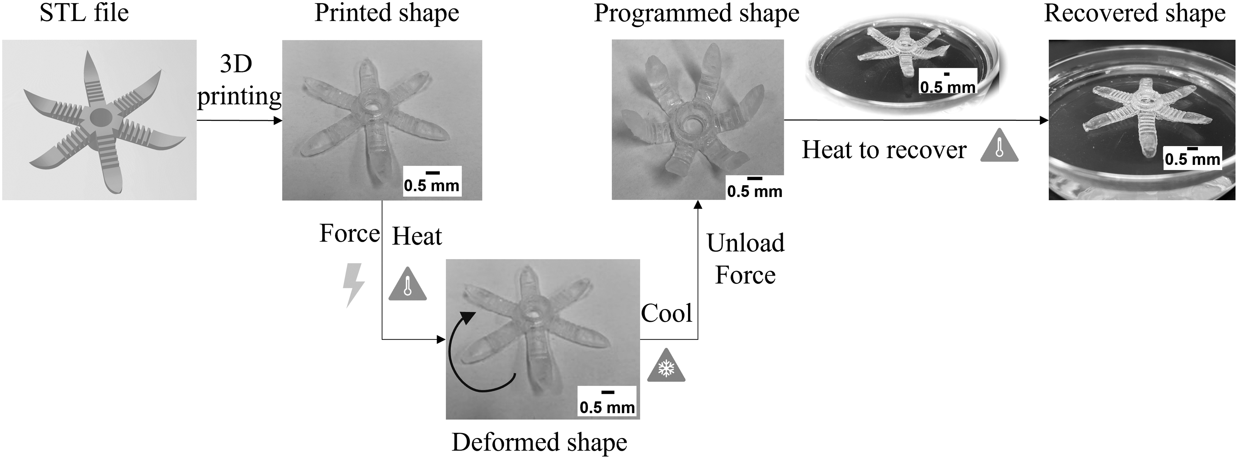
Illustration of four-dimensional printing with a constrained thermomechanism.
Upon completion of printing, the sample specimens undergo a shape memory cycle (SMC) consisting of shape programming and recovery. During the SMC, the thermoresponsive specimen is exposed to an external force and maintained at a predetermined temperature that is above the material's glass transition temperature of 43°C. Next, the printed specimen is cooled to room temperature and the applied load is removed, allowing the specimen to fix a temporary shape. Finally, the printed part is reheated to gradually recover the original printed shape of the part.
During the SMC, two measures are introduced to quantify the shape memory features of the 4D printed parts. More specifically, the shape fixity ratio Rf and shape recovery ratio Rr are raised to characterize the capability of printed parts to retain the temporary shape and recover its original shape, respectively. The two shape memory ratios are mathematically expressed in Equations (1) and (2), where er is the strain at the start of the free recovery process,
To investigate anisotropy in the shape memory behaviors of the 4D printed parts, a laser-based SLA system is used and modeled. In this study, the part is fabricated in a layer-wise manner through the photopolymerization process. The build direction is defined as perpendicular to the build platform, and a Cartesian coordinate system is established with the origin set as the point on the build platform with the shortest distance to the ultraviolet light, as demonstrated in Figure 2.
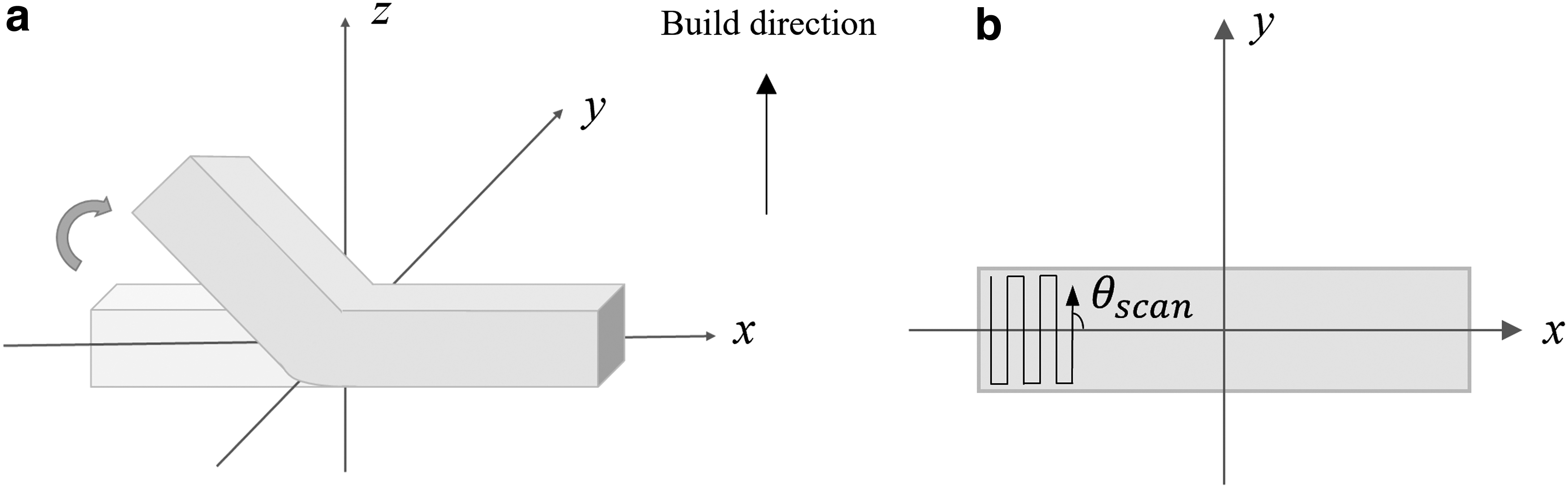
Illustrations of
As shown in Figure 2a, during the SMC, the external force is applied to the sample part along its length direction when heated to a prescribed temperature. In addition, the scanning angle
Printing time model
In this research, the total build time is evaluated in the 4D printing process and is modeled considering the layer-wise scanning time (i.e., when the laser is on) and traveling time (i.e., when the laser is off) of the laser, as shown in Equations (3)–(5):
The total layer number of the designed part is calculated as follows:
According to the Beer–Lambert law,
25
the scan speed of the laser is determined as formulated in Equation (7). It should be noted that the cure depth should be greater than or equal to the layer thickness; hence, the maximum scan speed is achieved when the cure depth equals the layer thickness.
In addition, critical energy in the above equation is calculated as follows:
Shape memory property model
Material preparation and experimental procedures
To quantify anisotropy in shape memory properties, a methacrylate-based shape memory polymer network is used as a model material. The polymer comprises benzyl methacrylate (BMA) as the monomer, poly(ethylene glycol) dimethacrylate (PEGDMA, average Mn 750 g/mol) as the cross-linker, and phenylbis (2,4,6-trimethylbenzoyl) phosphine oxide (BAPO) as the photoinitiator.
To prepare the material, the cross-linker, PEGDMA, was added dropwise to BMA at a 20 wt% ratio, followed by addition of BAPO (5 wt%) with continuous stirring on a magnetic stirrer. The solution was finally homogenized in a planetary centrifugal mixer. All chemicals were purchased from Sigma-Aldrich (St. Louis, MO, USA) and used without further purification. The printability of the material has been investigated in our previous studies.10,14
The specimens are printed as a rectangular bar with dimensions of 40 × 10 × 2 mm using a laser-based SLA printer. Following the printing process, the thermoresponsive specimen is exposed to an external force of 0.8 N while immersed in a water bath at a specific temperature,
Shape Memory Property Full Factorial Design
Given the major stages in an SMC, four critical deformation angles are proposed to calculate the shape fixity and shape recovery ratios, as shown in Figure 3.
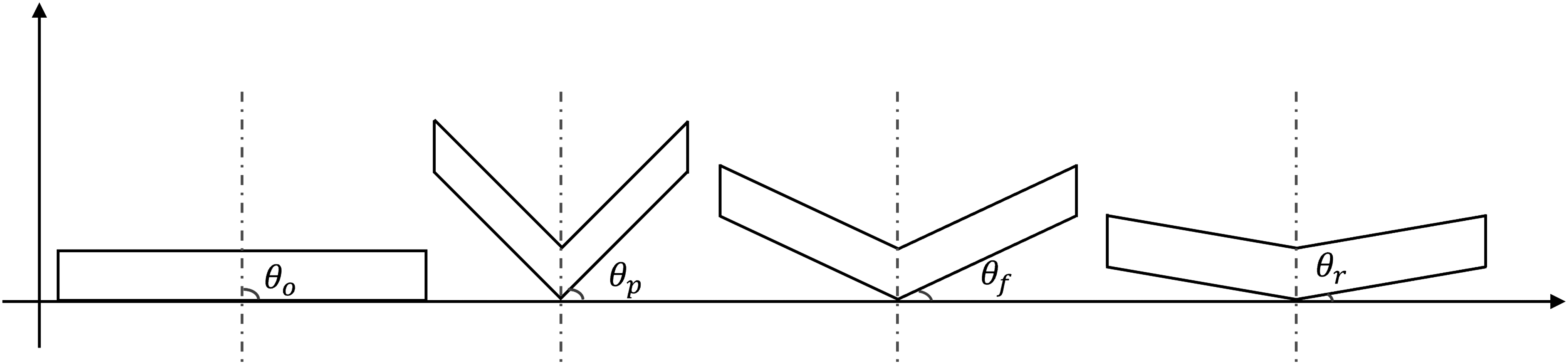
Deformation angles in a shape memory cycle.
In this figure,
Experimental design
To analyze the anisotropic shape memory behaviors of the 4D printed thermoresponsive parts, the DOE approach is first adopted to characterize the effects of critical process parameters on the shape memory properties, and then a pair of anisotropic indices (in reference to the Degree of shape memory property anisotropy section). Specifically, a full factorial design is proposed considering three critical process parameters with two levels, as listed in Table 1.
Three replications are performed to reduce measurement errors, and one center point is added to examine the linearity assumption of the DOE models. In this study,
Values of Printer and Model Parameters
All the measurement values are checked for outliers and suspected outliers are removed from the subsequent analysis. Additional experiments are performed when necessary.
Degree of shape memory property anisotropy
The anisotropic indices of the shape memory behaviors,
The degree of anisotropy in the shape memory behavior of 4D printed thermoresponsive components is characterized by the anisotropy level
Both the anisotropic index and the degree of anisotropy can be employed to quantify shape memory properties in different directions. More specifically, the larger the value is (close to one), the more the anisotropy in the shape memory property; on the other hand, the value of zero indicates an isotropic structure.
Results and Discussion
In this section, DOE models are established, and three case studies are conducted to further investigate and discuss the anisotropy in the shape memory property of 4D printed parts under distinctive scenarios. The printer parameters remain the same as indicated in Table 2.
DOE models
The DOE models (coded) of the shape fixity ratio and shape recovery ratio are obtained using Minitab software and shown as follows. The R-squared values for the regression models are 92.51% and 91.96%, respectively.
The corresponding Pareto charts indicate that the scanning angle has a negligible impact on the shape fixity ratio, while the layer thickness has an insignificant effect on the shape recovery capability. Moreover, the three-way interaction suggests ignorable influences on the shape memory behaviors of the 4D printed parts.
After removing the insignificant terms, the refined DOE models are shown in the following equations with R-squared values of 90.20% and 90.92%, respectively.
Anisotropy in 4D printed parts
Anisotropy in the shape memory property
According to the DOE results, the scanning angle and its two-factor interactions significantly affect the shape memory behaviors of the 4D printed parts, which also aligns with the observation by Dong et al. 29 As anisotropy emphasizes differences in the properties in different directions, it is imperative to further investigate how different scanning angles affect the shape memory properties. Hence, to better visualize the effects of the scanning angles on shape memory properties, the developed DOE model is used to calculate the shape fixity and recovery ratios at various angles of scanning. The results are depicted in Figure 4.
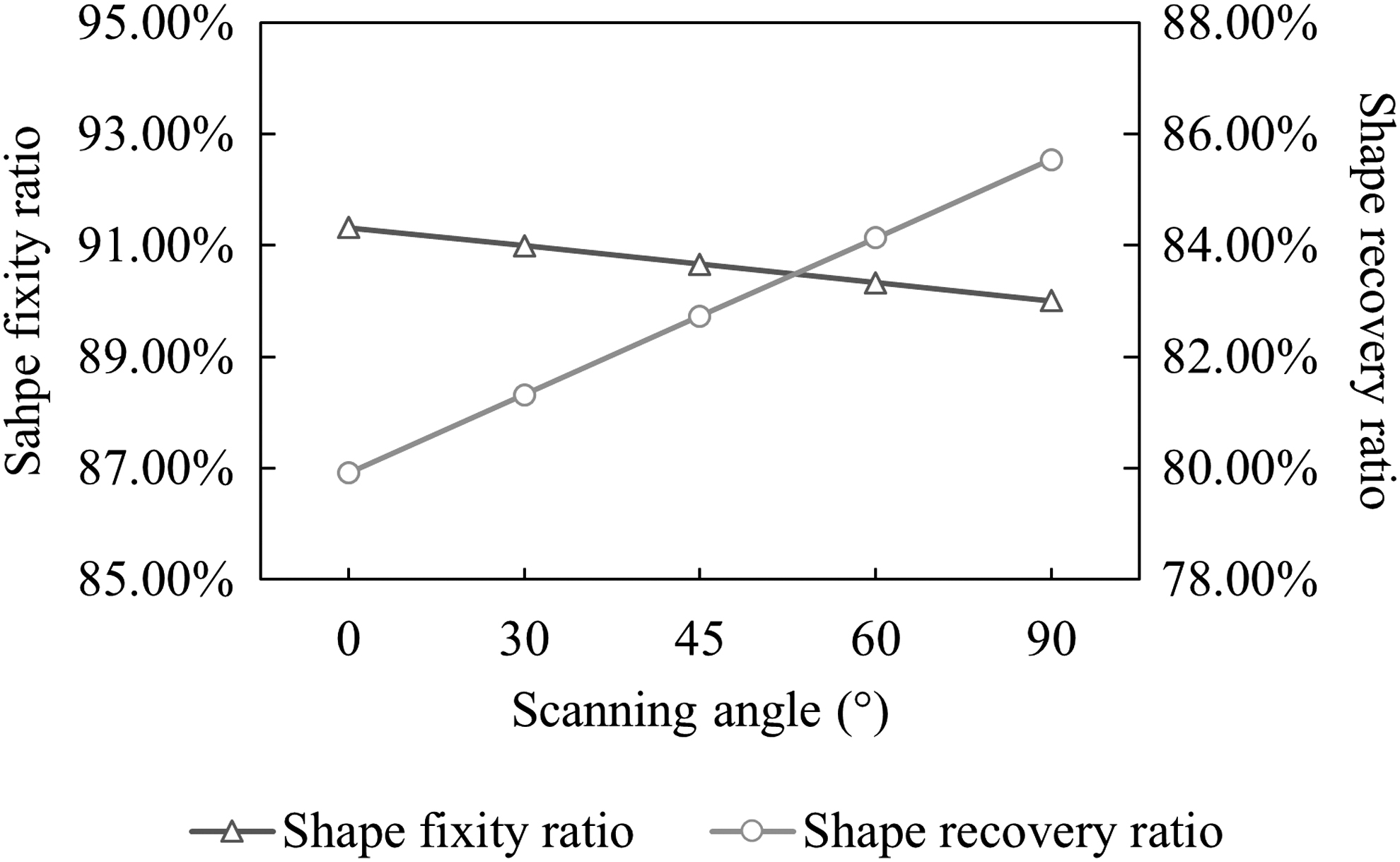
Effects of scanning angle on shape memory behaviors.
According to Figure 4, as the scanning angle of the part increases, the shape fixation level slightly decreases, while a significant increase is observed in the shape recovery level. This suggests that the scanning angle has a greater impact on the shape recovery capability than on shape fixation. A possible reason for this is the need for printed components to undergo shape programming before shape recovery can occur, which introduces additional sources of variation in the quantification of the shape recovery ratio.
Furthermore, the figure indicates that larger scanning angles make it harder to fix a temporary shape, but lead to a better recovery to the original shape. In addition, variations in the shape memory behaviors further confirm the presence of anisotropy in shape fixity and recovery properties.
Consequently, the degrees of anisotropy in the shape fixity and recovery ratios are quantified using Equations (14) and (15) and demonstrated in Figure 5. More specifically, Figure 5a shows the changes in the anisotropy degree corresponding to increasing layer thickness; meanwhile, Figure 5b exhibits the anisotropy levels with respect to different shape memory temperatures.
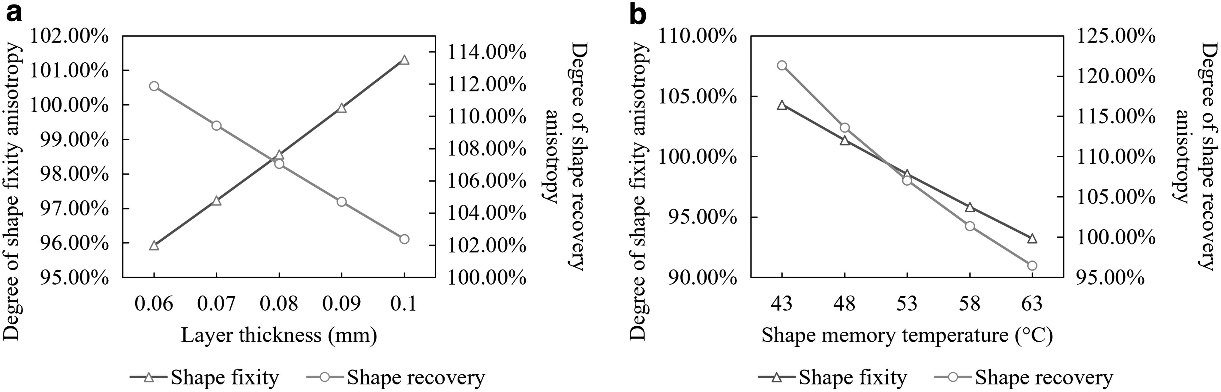
Degree of shape memory property anisotropy under the impact of
An anisotropy level of 100% indicates isotropy in the properties of interest, while a larger deviation from 100% suggests a larger difference between the same properties in different directions. As observed from Figure 5a, increasing the layer thickness leads to an increasing trend of anisotropy in shape fixation, and an opposite pattern to that is observed for shape recovery.
In other words, as the layer thickness increases, a smaller difference is observed in shape fixity and recovery ratios in two directions, suggesting that a larger layer thickness helps reduce the anisotropy in shape memory properties within the testing range. Moreover, Figure 5b suggests reduced anisotropy in shape recovery when the temperature increases by 20°C from the glass transition temperature (43°C) of the materials, while anisotropy is minimized for shape fixity at around 50°C.
Shape memory property anisotropy in different scanning patterns
In addition to the Line scanning pattern, other patterns are also commonly used for layer-wise scanning in the SLA system. Consequently, this case study is designed to understand and experimentally evaluate how different scanning patterns affect the anisotropy level in the shape memory properties.
Moreover, in contrast to a fixed scanning angle used for every layer, as described in Anisotropy in shape memory property section, two scanning angles are iteratively employed to produce sample specimens for all the experimental analyses. The experimental design is summarized in Table 3, in which the values of scanning angles indicate the respective scanning angles of the odd and even layers.
Experimental Design for the Scanning Pattern
By applying the scanning patterns listed in Table 3, the sample specimens are printed out and processed for shape programming and recovery for analysis. In this case study, all the specimens are printed with a layer thickness of 0.08 mm, a scan speed of 2.5 mm/s, and an infill rate of 80%. The operating temperature during the SMC is set at 53°C, and both the hold time and shape recovery time are set as 1 min. Note that each sample is printed with five replications, and the outliers are checked and removed in the analysis.
The experimental results are demonstrated in Figure 6, where variations in the degree of the shape memory property anisotropy corresponding to specimens printed with different scanning patterns are compared. More specifically, the results shown in this figure indicate the difference between the calculated level of relative anisotropy, as determined by equations presented in the Degree of shape memory property anisotropy section, and the value of one (i.e., isotropic uniform structure). The absolute magnitude, on the other hand, represents the degree of anisotropic behavior.
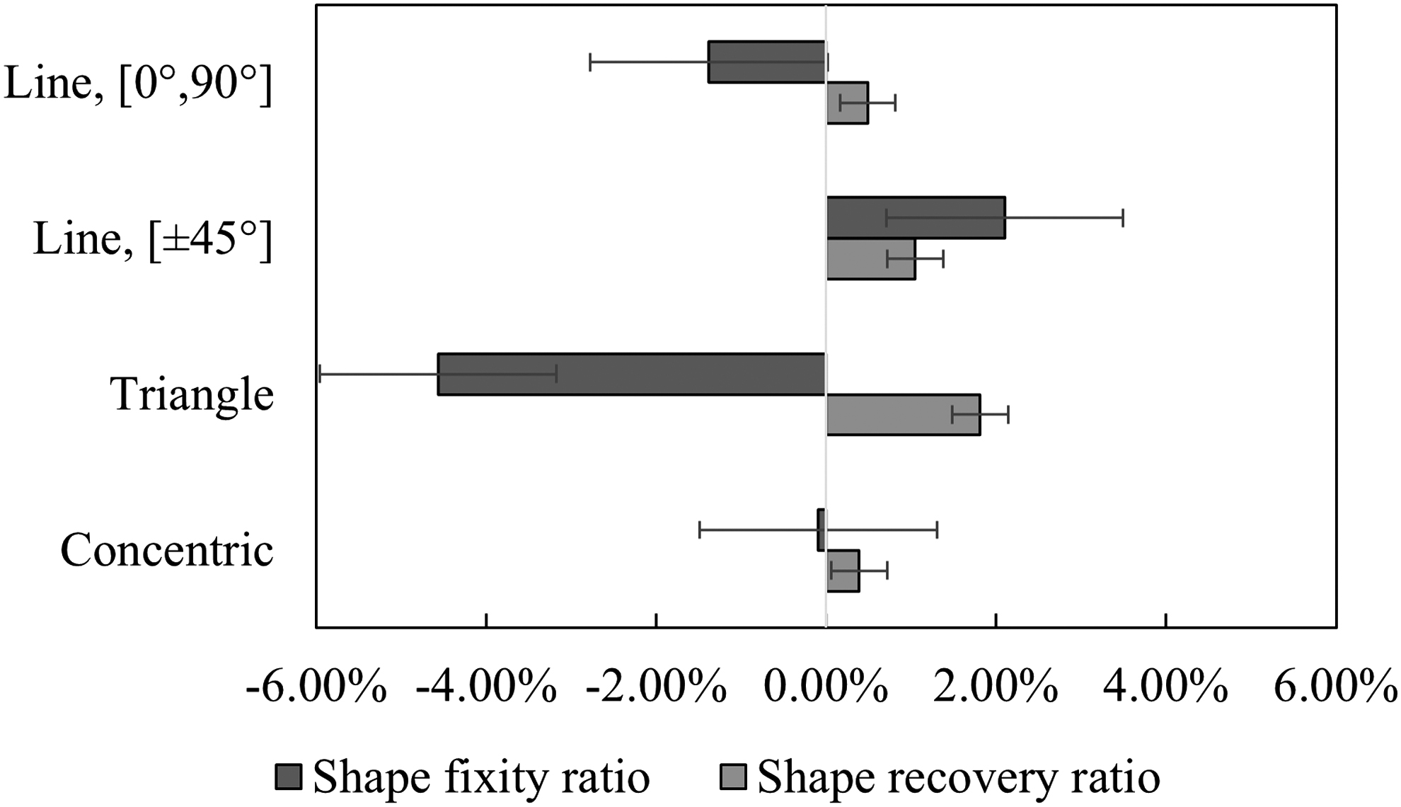
Variations in the degree of anisotropy in shape memory property for different scanning patterns.
According to Figure 6, the scanning patterns greatly affect the anisotropy degree of shape memory properties, while the scanning angle shows relatively minor impacts. More specifically, among the four discussed scanning patterns, the Concentric pattern leads to the smallest variation in the degree of anisotropic shape memory behaviors, indicating insignificant differences in shape memory properties along different directions. On the contrary, the Triangle pattern reveals the largest variations for shape memory properties in the x and y directions. Given the experimental results, it is reasonable to suppose that anisotropy can be tailored by jointly adjusting the scanning pattern and angle.
Next, the printing time is computed for the four cases listed in Table 3. As demonstrated in Figure 7, the scanning patterns play an important role in the total production time. Particularly, among the four scanning patterns, adoption of the Triangle pattern leads to the longest printing time, and the Line pattern with scanning angles alternating between 0° and 90° has the shortest printing time. The differences in printing time are because a longer travel distance is observed in the Triangle pattern, while Line patterns result in a shorter total traveling distance of the laser.
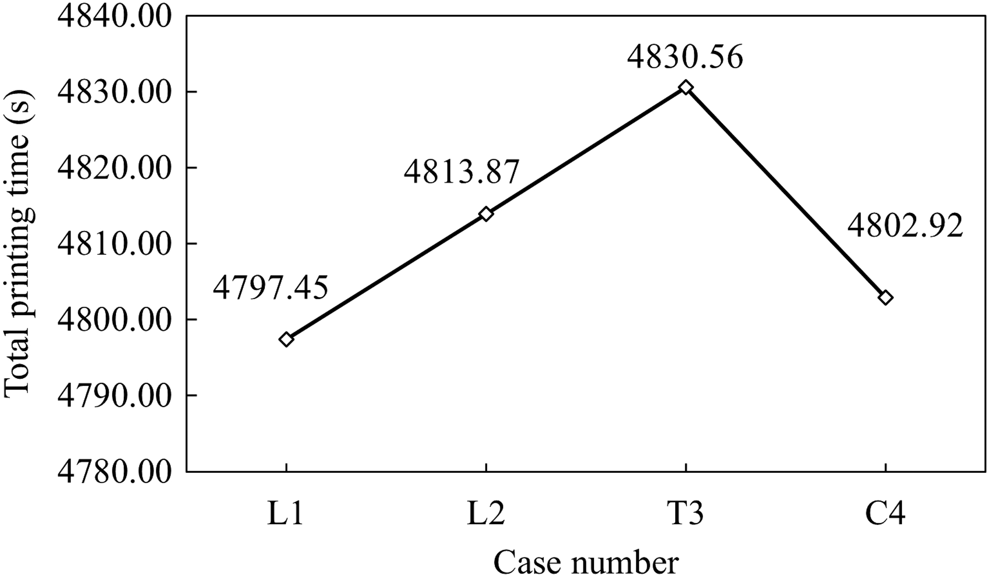
Total build time for specimens printed with different scanning patterns.
Although no significant reduction in the total printing time is reported when changing the scanning pattern, it shows promise for improving the productivity of batch production. Given the fact that the scanning pattern can affect both the degree of anisotropy and the build time, it is necessary to wisely select an appropriate scanning pattern and other process parameter values toward achieving the desired anisotropy degree and production speed.
Anisotropic shape memory behavior optimization
In this section, an optimization problem is formulated to examine the effectiveness of the established models in selecting the values of the parameters (i.e., layer thickness, scanning angle in the Line pattern, and shape memory temperature) toward achieving the desired anisotropy level of shape memory properties with joint consideration of total printing time.
The anisotropies can provide important information regarding the internal structure of the printed products; however, their varying degrees not only affect the setup in the subsequent postprinting processes (e.g., the positioning angle of part in the associated postcuring process) but also limit the applications of the products. As a result, two scenarios are discussed as follows.
In most cases, anisotropy is undesired for applications such as molds. Therefore, for scenario I, the objective is to minimize both the anisotropy in shape memory behaviors (with minimum shape fixation and recovery ratios of 95%) and the total built time, which complies with the requirement of isotropic or near-isotropic product performance.
Subject to
For scenario II, the objective is designed to fulfill the application requirement for a more general purpose, which often requires stronger strength in a certain direction (e.g., the direction of shape programming). Therefore, the objective function is defined to maximize the degree of anisotropy and minimize the total printing time. The constraints remain the same as the first scenario, as formulated in Equation (23).
The optimization problems are solved using MATLAB and results are summarized in Table 4. Note that min-max normalization is used for the optimization problem, and each objective is weighted equally. The results shown in Table 4 further confirmed the significance of the scanning angle and shape memory temperature in anisotropy. In addition, to eliminate anisotropy to the most extent, the smallest scanning angle should be used. On the other hand, to exploit the anisotropy and maintain a satisfactory level of shape-morphing capabilities, a higher temperature within the value domain is preferable.
Parameter Values of the Optimization Case Study
The corresponding shape memory property-related parameter values and the total printing time for the two scenarios (i.e., minimized and maximized anisotropy levels) are illustrated in Figure 8. As can be observed from Figure 8, both cases suggest a similar level of shape memory behaviors (∼95%) in regard to shape fixation and recovery. In addition, a longer total build time is expected when the anisotropy level in the shape memory properties is increased while ensuring the desired shape memory behaviors.
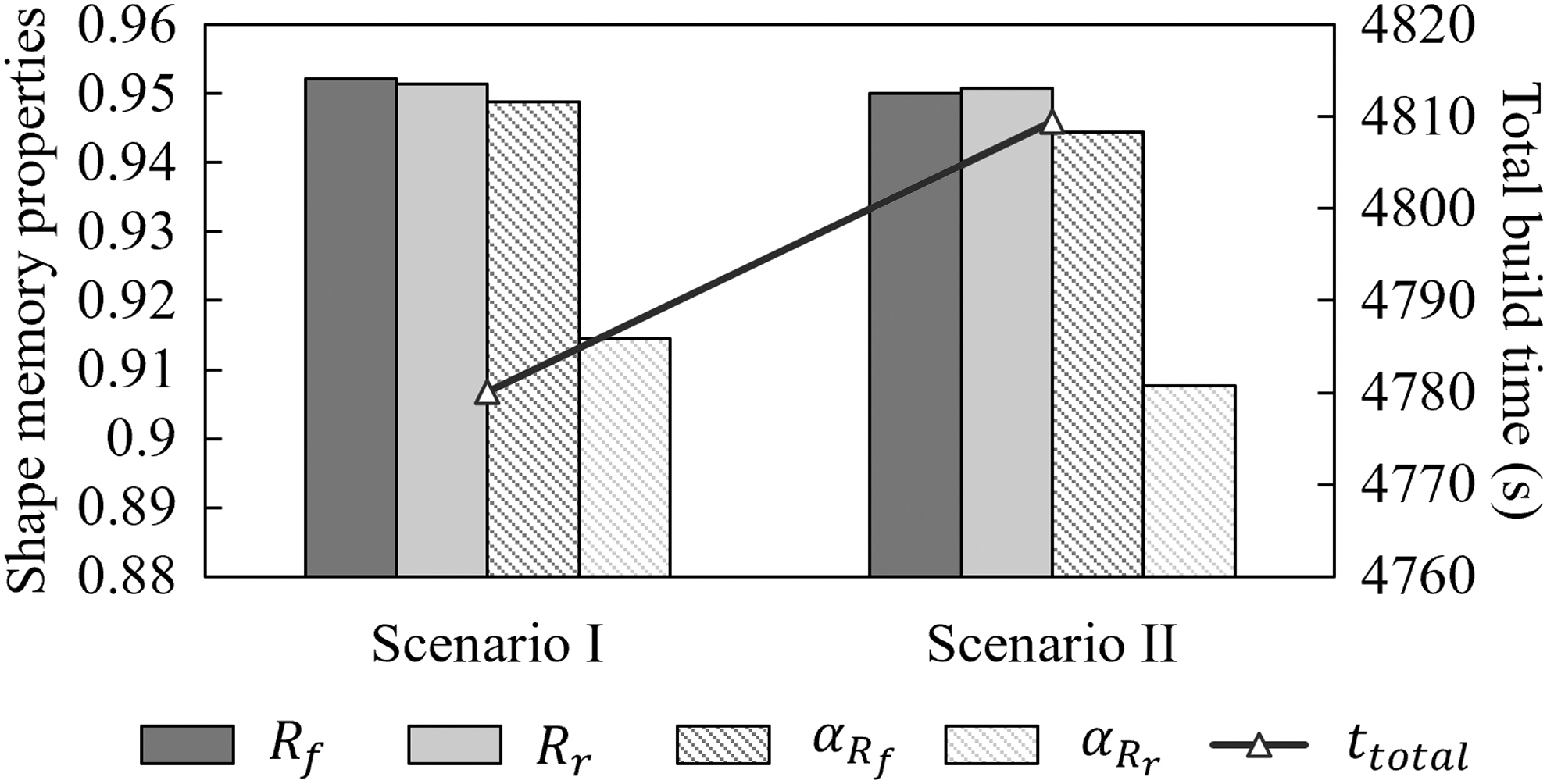
Optimization results with respect to the best sets of parameters in scenarios I and II.
Conclusions and Future Work
In this study, mathematical models are first established to study the anisotropy behaviors of shape memory properties of 4D printed thermoresponsive parts. Specifically, the DOE approach is used to investigate the influence of critical process parameters on the shape fixation and recovery capabilities of printed parts, and the results report variations in shape-shifting capabilities along different directions. A series of experiments are then conducted to analyze anisotropy in shape memory properties under different printing scenarios. The results of this study confirm the existence of anisotropy and suggest that the Concentric printing pattern leads to the minimum degree of anisotropy, approximately 0.1%, whereas the Triangle pattern suggests an opposite trend with 4.6% as the extent of anisotropy. Furthermore, the feasibility of controlling the degree of anisotropy is examined and demonstrated in Line printing patterns by selecting different values of process parameters.
As an extension of this work, more parameters can be considered to evaluate the degree of shape memory property anisotropy, especially from the printing process. In addition, the anisotropy behaviors along the build direction can be discussed, and variations in anisotropy can be further investigated while promoting the shape memory properties.
Footnotes
Authors' Contributions
J.Z. was involved in conceptualization, data curation, investigation, validation, and writing—original draft. M.H. was involved in investigation, validation, software, formal analysis, and writing—original draft. L.L. was involved in conceptualization, methodology, investigation, supervision, and writing—review and editing.
Author Disclosure Statement
No competing financial interests exist.
Funding Information
No funding was received for this article.