
Abstract
3D printed fashion products have become a trend. This article explains use of fused deposition modeling technology for 3D printing of fabrics with thermoplastic polyurethane flexible filament. A total of 15 structures of fabric were designed and printed for fabric performance tests. The fabric structures were “woven-like.” Those fabrics were printed by 0.8, 1.0, and 1.5 mm nozzles, separately. Meanwhile, the fabrics had various layer heights, but total thickness of the fabric was fixed at 0.6 mm. The strongest fabric could resist up to 460 N in ball burst test. In tensile test, the strongest fabric was broken at 230 N and maximum elongation was 647% at break. Besides, the failure performance was analyzed, recovery ability of fabric was also evaluated. The least deformation of the fabric was 2.5% after stretching with 60 N and releasing for five cycles. These results of the fabric performance could be a database and a reference for designing the structure of an apparel or a garment.
Introduction
3D printing technologies have been widely applied in different aspects. In the traditional manufacturing industry, product designers may employ it to fabricate prototypes before mass production. 1 The seven types of 3D printing technologies were summarized as follows: material extrusion, vat polymerization, powder bed fusion, material jetting, binder jetting, direct energy deposition, and sheet lamination. The main benefit of vat polymerization, powder bed fusion, material jetting, and binder jetting is the dimensional accuracy, whereas microelectromechanical systems is embedded into the machine. In this research, fused deposition modeling (FDM) would be employed with the reason of FDM 3D printer has the advantages of low waste, variety of materials usage, and it is a low-cost machine. 2
In the fashion industry, accessories are commonly manufactured by 3D printing.3,4 Several 3D printing technologies offer enhanced excellent appearance to the products, directly becoming an end-use product for commercial sale. The smooth appearance is generally appreciated by consumers and the raw textured products made with 3D printing are also being used.5–10 Apparel directly manufactured with various 3D printing technologies are also gaining acceptance.
3D printed fabrics and garments have been investigated by designers and researchers all over the world. Most of the products are printed by rigid materials such as polylactic acid,8,9 nylon,7,8,10 polyethylene terephthalate, 8 with interlocking or chain structure, to achieve “semi-flexible” structure and feel. Mark had designed knitted fabric with several different structures and printed them with Nylon PA12 powder by selective laser sintering. 7 These fabrics can be stretched and they bounce back into the original shape because of the elasticity of PA12. Mark also found that the diameter of the pipe was directly affecting the mechanical performance of the fabric and 1.2 mm diameter of the pipe had better recovery ability than 0.6 and 0.4 mm pipe. 7 While the fabric was “knitted” with 0.4 mm pipe, only limited stretching could be performed. 7
Besides knitting, weaving is another common method to fabricate a fabric. Leonie et al. demonstrated two “3D woven” fabrics made from acrylonitrile butadiene styrene (ABS) printed with FDM. 11 One of the fabrics was printed in zigzag shape in both warp and weft. Another fabric was first printed in vertical cylindrical pillars as the warp, then the nozzle moved in zigzag or wave to extrude material, without supporting material under it, similar to a bridge, as the weft. Leonie et al. found that the fabric with the warp and weft both in zigzag had similar shear modulus in both warp and weft direction.
For the fabric with pillar-shaped warp, shear modulus in weft direction was stiffer than the warp direction and it was 1.5 times stiffer than the first fabric. 11 Haruki and Jeeeun also investigated similar “3D woven” fabrics. 9 The fabrics were FDM 3D printed with multimaterials. The team employed the pillar-shaped warp as the fabric structure. Conductive ABS was used for weft. The fabric was connected with electricity to light up an LED. The team also demonstrated that the textile pattern on the fabric can also be created by assigning the path of the nozzle when “weaving” the weft. 9
However, those fabrics were made with rigid materials and because of the clearance required between the printed “yarn,” fabric thickness makes it difficult to have enough flexibility to fit the body shape and provide comfort for wearing. Hence, flexible materials, such as thermoplastic polyurethane (TPU), have greater potential for fabricating a garment product.12–14 Meanwhile, topologists have developed mesh structures and auxetic structures, exhibiting creative dynamic deformation when pulling or compressing it. They are widely accepted by fashion designers for garments with 3D printing.
Tatjana et al. demonstrated several auxetic structures as fabric swatches that can be FDM 3D printed with TPU in different colors. 10 The team then used a 3D pen to join the swatches for making a dress. It showed flexibility and elasticity when put on a mannequin. A survey was carried out to ascertain views of the public on 3D printed garments. 10 The results showed that nearly 80% of respondents were feeling positive when wearing a 3D printed garment. 10
However, these structures eventually developed holes, which weakened the mechanical performance of the garment. 15 The big demand for performance garments and the rapid development of 3D printing of textiles and 3D printed garments with different structures should be evaluated. In this research, FDM 3D printed TPU fabrics of 15 different structures were evaluated by common fabric performance test standards.
Experimental
The fabric design and printing
Woven-like fabrics were designed with SolidWorks (Fig. 1). The fabrics had two to six layers with different layer heights, but the total thickness was fixed at 0.6 mm. The layer thickness was T = 0.10, 0.12, 0.15, 0.20, and 0.30 mm. Meanwhile, width of the “yarn” was W = 0.8, 1.0, and 1.5 mm, depending on the diameter of the 3D printer nozzle. Therefore, 15 structures of fabrics were created (Step 1 in Fig. 2). In each layer, only warp or weft was printed and this was done alternately. If warp was printed in one layer, weft was printed in the next layer.
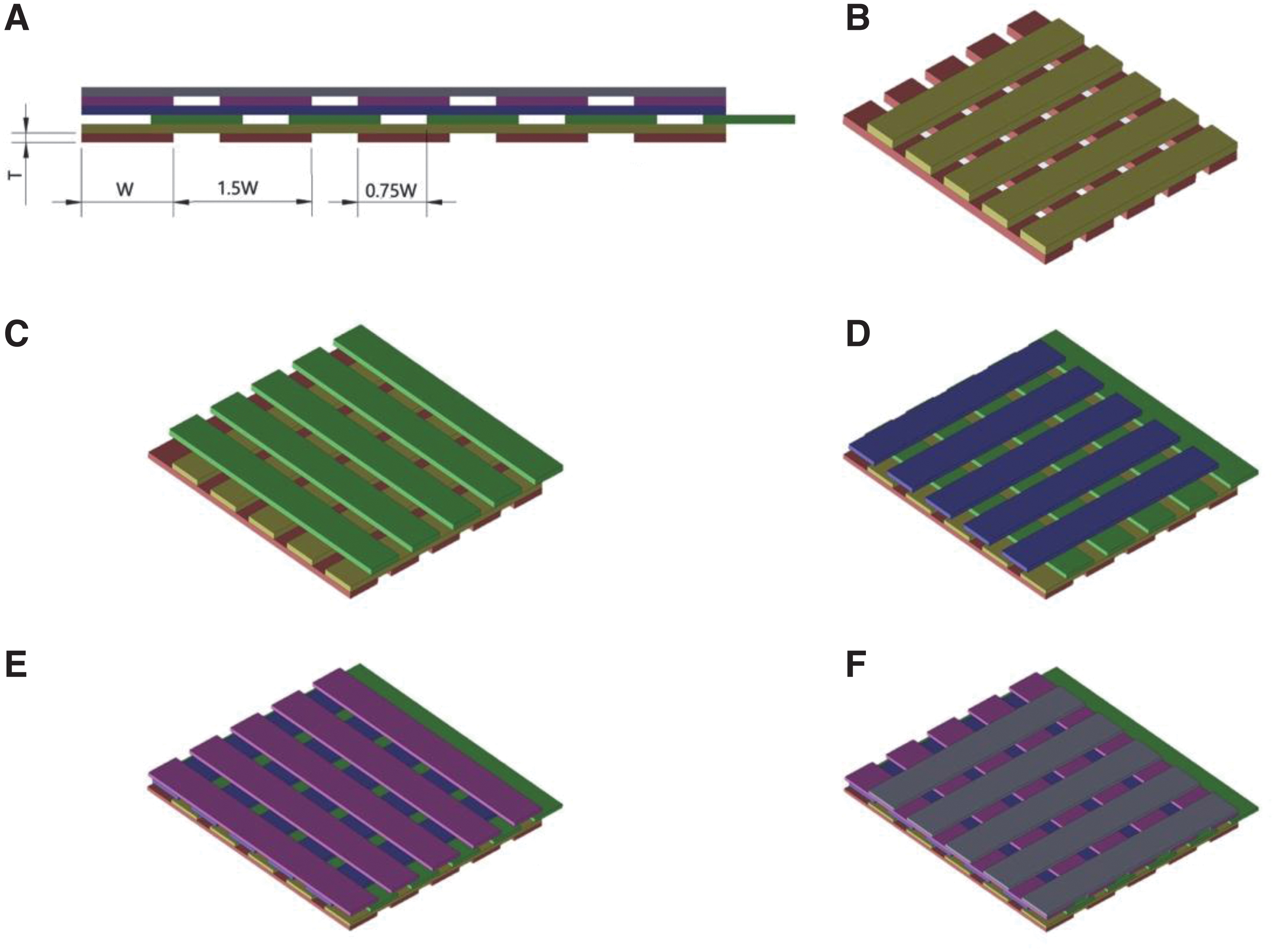
Illustration of different fabric structures.
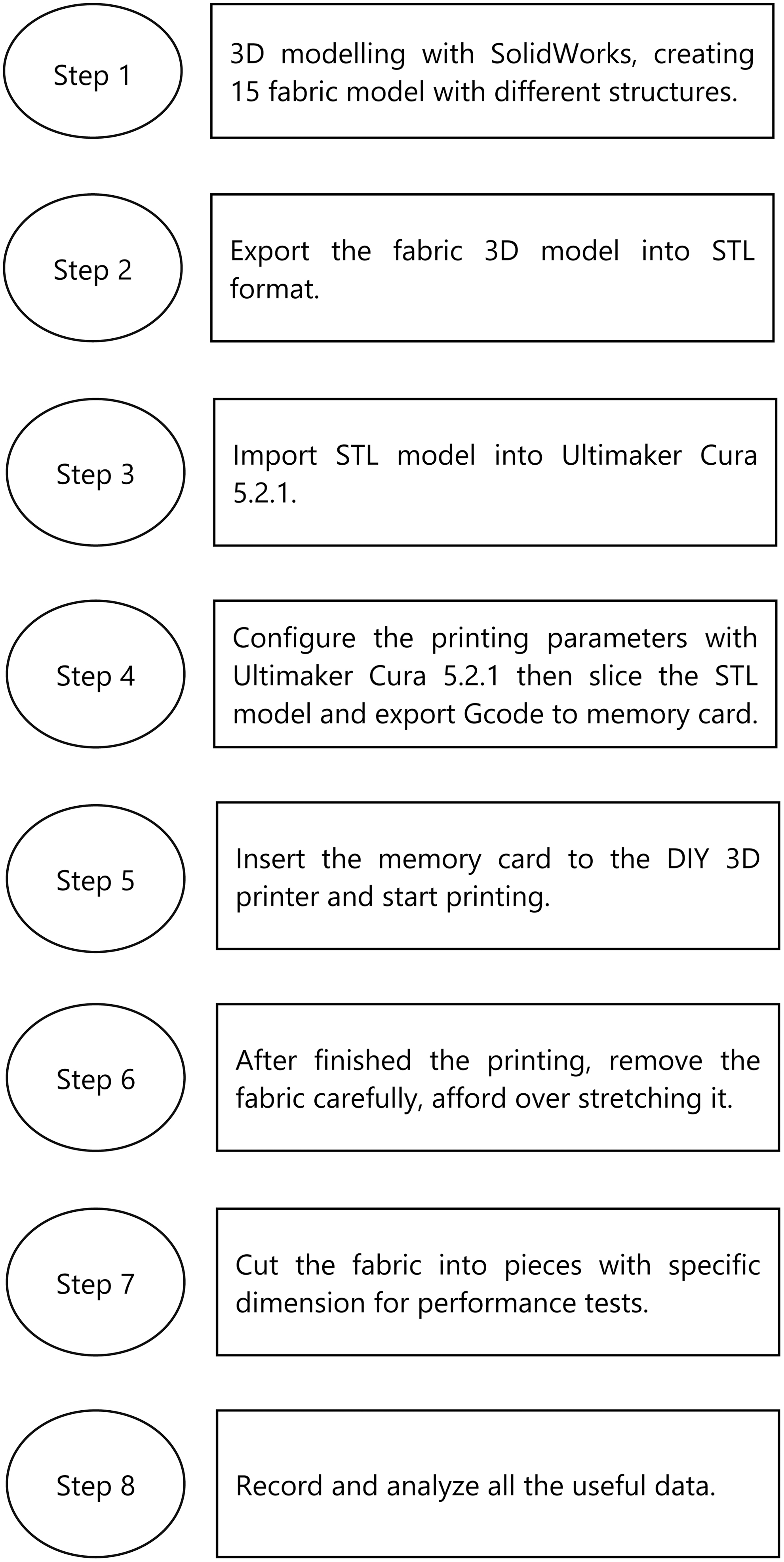
The experimental flow of this research.
In the first layer, assigned as L = 1, warp was printed along the Y axis. In the second layer, assigned as L = 2, weft was printed along the X axis. The gap between each “yarn” on the same layer was half of the nozzle diameter (W/2). The third layer (L = 3) was the same as the first layer, but each “yarn” was shifted along X axis by 0.75W. The fourth layer (L = 4) was the same as the second layer, but each “yarn” was shifted along Y axis by 0.75W. The fifth and sixth layers were exactly the same as the first and second layer, respectively.
The fabrics were printed with a do it yourself (DIY) FDM 3D printer. The control board of the 3D printer was Makerbase Monster 8 V1.1. A 32-bit ARM core was there on the board and the firmware, Marlin 2.1.1 was built inside. The XY motion was driven by THK 2040 ballscrew, coupled to 57-steppers. The Z axis was driven by two cylinder lifts, actuated by 42-stepper motors. The steppers were powered and controlled by M415 stepper drivers with 32 microstepping for XY axis, and 16 microstepping for Z axis.
The maximum theoretical resolution was 6.25 μm for XY axis and 0.273 μm for Z axis. The print bed was a 5 mm thick ROBAX high temperature-resistant glass. It provides excellent flatness and near zero thermoexpansion, maintaining the flatness even when the bed is heated. A dual gear direct extruder and exchangeable MK8 nozzle was installed on the printer. The dual gear extruder provides stable feeding of TPU filament to the nozzle without buckling.
The used material in this research was Recreus Filaflex 70A filament with 2.85 mm diameter. Besides this TPU filament, which can be found in the market, a novel TPU filament composited with cellulose powder was developed. The TPU (Soft 45A12P) with Shore A45 hardness was produced by Badische Anilin und Soda Fabrik. Then it was compounded with 10% α-cellulose powder by a twin-screw extruder and formed into filament. Before starting printing, green polyethylene terephthalate tape was coated onto the glass, increasing the adhesion between TPU and the print bed.
The layer height and the nozzle diameter were varied. The nozzle temperature was fixed at 270°C, hence the feedrate was configured with the slicer Ultimaker Cura 5.2.1 for different structures, (Step 4 in Fig. 2) to ensure steady extrusion of TPU. The specific configurations are listed in Table 1. The “yarn” on the upper layer was a bridge structure to the lower layer. To ensure the bridge can be built, except the first layer, starting from the second layer, the extrusion flow was set to 150%. The 3D printed fabric with structure 11 is shown in Figure 3. The edge would be cut before performing the following fabric performance tests. (Step 7 and 8 in Fig. 2).
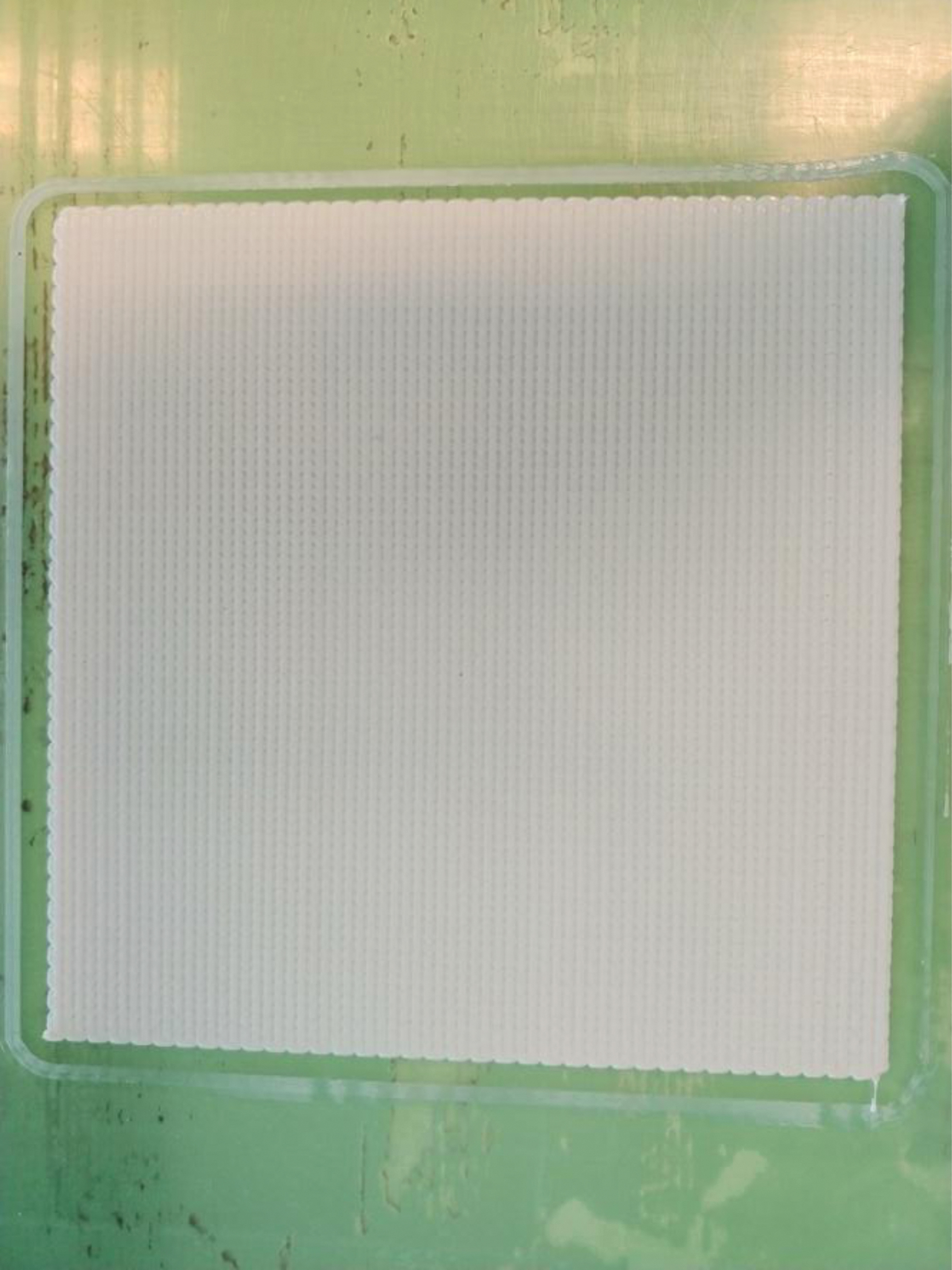
An image of 3D printed fabric with structure No. 11.
Print Settings of Different Fabric Structures
Fabric performance
The 3D printed “woven-like” fabrics with all 15 structures (Table 1) were subjected to several tests to evaluate the fabric performance. Ball burst test according to ASTM D6797-15 measures the maximum breaking force of lowest extension in any direction on the fabric. 16 Breaking force and elongation of the fabric were tested according to ASTM D5035-11(2019). Pure warp and weft directions were tested. The recovery ability of the fabric was determined according to EN 14704-1:2005. The residual length was measured after stretching the fabric in warp and weft direction.
The testing instrument Instron 4411 equipped with 5 kN loadcell was used for all the tests listed earlier. In ball burst test, a fixture was installed on the machine, which allows the ball to move down for maximum 80 mm from the fabric sample at 305 mm/min. For testing of breaking force and elongation, the fabrics were stretched at 300 mm/min until it break. The maximum tensile load and final extension were recorded. In the test of recovery ability of the fabric, the fabric sample was first extended at a constant rate of 100 mm/min until reaching 60 N load, which is twice the requirement stated in the standard.
Then the fabric was held for 1 min and then it was allowed to return to its original shape as a cycle. After five cycles were performed, the fabric specimen was released from the clamps and measured for the residual length. Furthermore, the frictional force was measured to evaluate the hand feel of the fabric. A 1 kg weight was loaded above the fabric specimen and placed on a black ceramic glass flatly. A load cell was coupled to the fabric and was pulled slowly, until the fabric slid.
The maximum force would be recorded before the fabric slided, it would be treated as the frictional force. Four types of fabric would perform the hand feel test. 3D printed fabric made with Recreus Filaflex 70A filament, the pure TPU (Soft 45A12P) and the cellulose/TPU composited filament mentioned earlier. Those were printed with structure 8. On the another side, a commercial double-knitted fabric was contenting 60% cotton, 34% polyester, and 6% spandex would also perform the hand feel to show the comparison.
Results and Discussion
Fabric density and printing time
An important issue in 3D printing could be the printing time and hence printing time of the fabric was recorded (Table 2). Fabric structure 1 took the longest printing time, for 1 m2 of fabric. It took 1560 min to print. It was because the fabric structure 1 was printed with the smallest nozzle used in this research, 0.8 mm nozzle, and included six layers.
The Fabric Density and Printing Time of Fabrics
The most nozzle moving path was needed to complete a fabric. Printing of fabrics with structures 14 and 15 took the least time, 819 min for 1 m2 of fabric. It was 1.9 times faster than fabric structure 1. Although the printing time affects manufacturing cost, material cost correlates to the fabric weight. The lightest fabric structure is structure 4, 505.13 g/m2. The fabric of structure 12 was the heaviest, 609.03 g/m2.
Ball burst strength
Besides, the 3D printed fabric depends upon the weight and the printing time, fabric performance was also evaluated. Ball burst strength was first tested (Table 3) and 11 out of 15 structures of 3D printed fabric were found not broken during the ball burst test. However, some of the fabric specimens with structure 5, 10, 11, and 15 were broken. The probability of no break was 50%, 50%, 50%, and 0%, respectively. Compared with the no break fabric specimens, structure 1 had the largest loading of 460.82 N when the machine reached its limit.
The Ball Burst Strength of Fabrics
The fabric structure 9 had the weakest loading of 252.40 N, but it was not broken. Results of structures 5 and 10 show that the maximum load of no break fabric and broken fabric has similar value. It shows that although the fabric did not break, it may have been close to being broken at that loading. In the ball burst test, all specimens with two-layer structure (Fig. 1B) had the probability of being broken. This was because the two-layer structure is similar to a mesh fabric, which contains holes.
The ball can enlarge the hole and go through it. As a result, 3D printed fabrics designed with structure 5, 10, and 15 are not recommended. Furthermore, all the fabrics with structure F had the results of highest loading, compared in the group of the fabrics printed with the same nozzle diameter. As this finding, structure F is more suitable to be applied to the portion of knee and elbow of apparel.
Tensile performance
The weakest isotropic strength of 3D printed fabrics was evaluated with ball burst test. The specific tensile performance of the fabric warp and the weft was further evaluated as per standard ASTM D5035-11. The results are listed in Table 4, Fig. 4, Fig. 5 and Fig. 6. The 3D printed fabric with structure 11 has the stiffest elastic modulus at 5% strain in warp direction, and structure 10 has the lowest value, 131.95 and 61.79 N, respectively (The blue bars of No.11 and No. 12 in Fig. 6). In the weft direction, the stiffest is structure 12 with a value of 199.26 N. (The orange bar of No.12 in Fig. 6). The most flexible in weft is structure 9 that has the elastic modulus 57.29N. (The orange bar of No. 9 in Fig. 6). The elastic modulus as the fabric tensile performance before it breaks was evaluated.
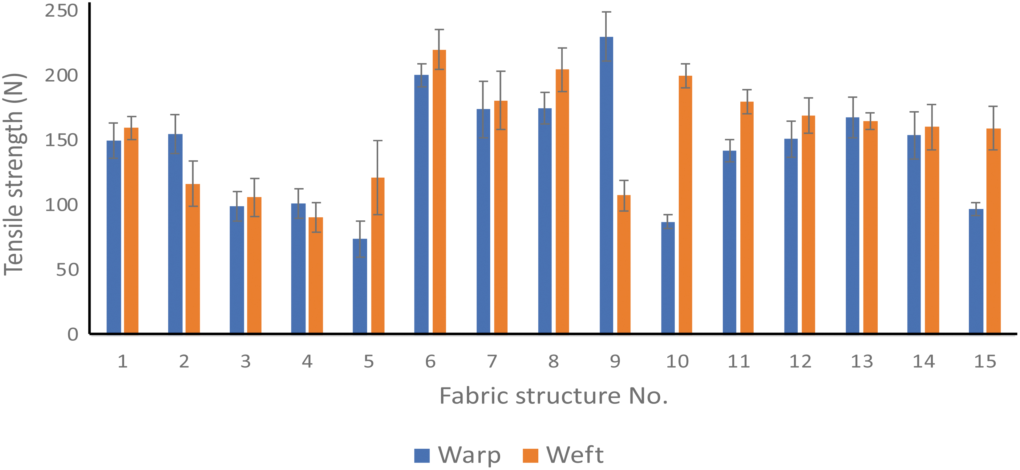
The tensile strength of 3D printed fabric in the warp and the weft direction.

The elongation at break of 3D printed fabric in the warp and the weft direction.
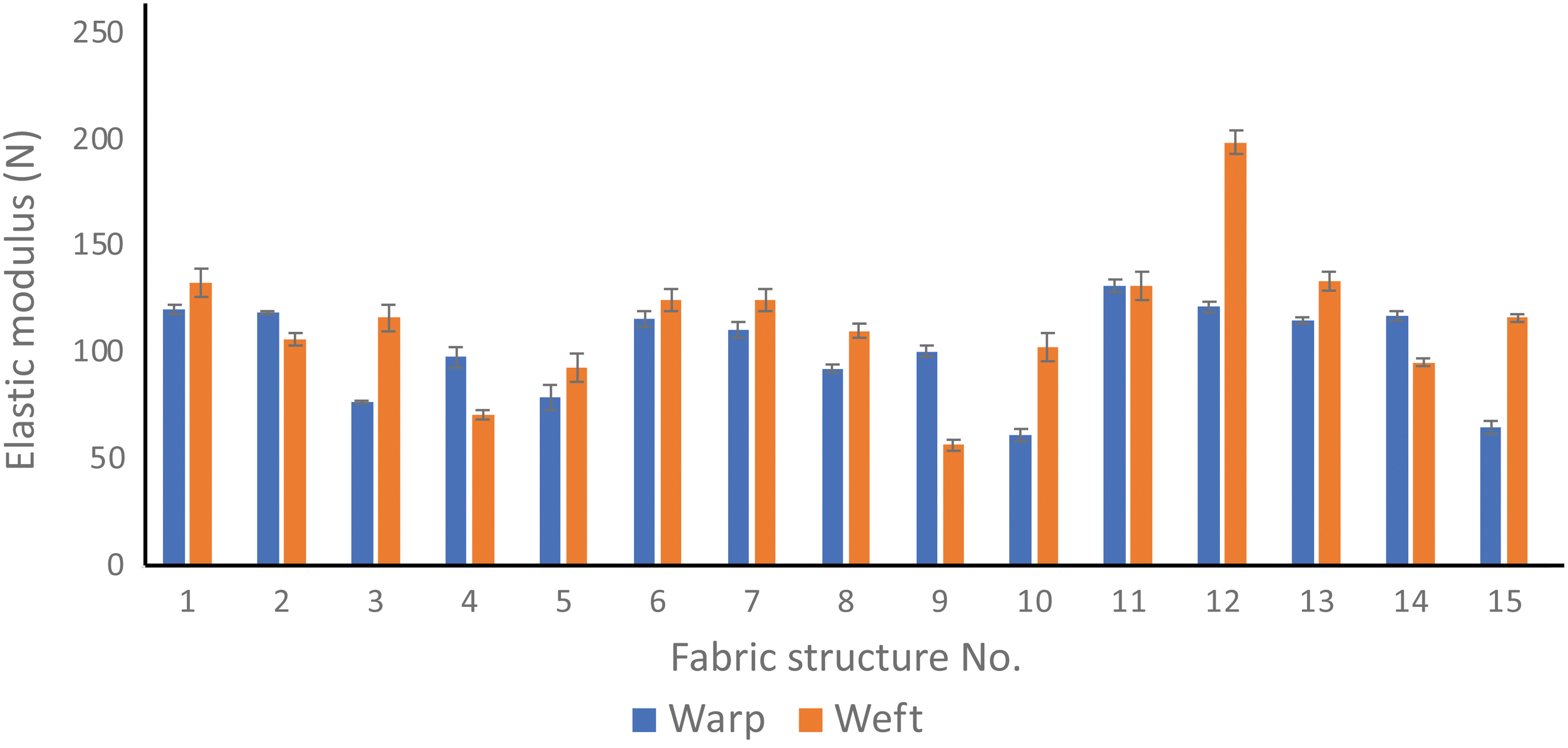
The elastic modulus at 5% strain of 3D printed fabric in the warp and the weft direction.
Tensile Performance of Fabrics
Values are presented as means ± SD.
The upper values at each role are the results of the warp direction.
The lower values at each role are the results of the weft direction.
Meanwhile, the tensile breaking strength and elongation at break were also tested. The fabric with structure 9 has the strongest warp and it was broken at 231.0 N. The strongest weft is of the fabric printed with structure 6 and the breaking force is 220.88 N. The highest warp elongation at break is that of structure 7 and it was stretched 647.13% before breaking. (The blue bar of No.7 in Fig. 5). The weft of the fabric with structure 5 has the longest elongation at break; it elongated 626.56% until it broken. (The orange bar of No.5 in Fig. 5). No significant correlation was found between the elastic modulus, tensile breaking strength, and elongation at break.
Value of elastic modulus has a correlation with fabric structure. Fabrics with even number of layers, two-layer, four-layer, and six-layer (Fig. 1), have a stiffer weft than the warp. In contrast, fabrics with odd number of layers have a stiffer warp than the weft. This can be explained with the difference in fabric structure. Only the warp first layer was 100% extrusion flow. All layers above the first layer were printed with 150% extrusion flow. For fabrics with even number of layers, the weft would have a larger amount of material than the warp.
In contrast, fabrics with odd number of layers would have more material in warp. The more material the direction had, the stiffer the direction would be. For example, in a four-layer fabric, the warps are constructed with a 100% extrusion flow warp layer and another warp layer would be printed with 150% extrusion flow. Meanwhile, there would be two weft layers printed with 150% extrusion flow. For a three-layer fabric, the warps were printed the same as the four-layer fabric, but it would have only one weft layer printed with 150% extrusion flow.
Values of tensile strength and elongation at break were measured as an evaluation of toughness of the fabric. However, we do not break the apparel or garment in our daily lives. Thus, recovery ability tests of both the warp and the weft direction were also performed. The results are listed in Table 5. Comparing deformation of all 3D printed fabrics, the fabric printed with structure 12 has the least deformation in both the warp and the weft direction after 60 N loading.
The Elasticity and Recovery Ability of Fabrics
The upper values at each role are the results of the warp direction.
The lower values at each role are the results of the weft direction.
The warp of the fabric elongated 5.0% after removing the loading. When the fabric specimen was rested for 30 min, it recovered half of deformation, as the final elongated length was 2.5%. The weft of the fabric was stretched longer than its warp. It was elongated 7.5% after releasing the stress. Then the warp had recovered one-third of deformation after 30 min. The final deformation was 2.5%.
Results of elastic modulus in Table 4 and elasticity of the fabric in Table 5 show that the elastic theory holds. The weft of the 3D printed fabric is always stiffer than the warp, if the fabric is constructed with even number of layers. For fabrics with even number of layers, the residual length of its weft after removal of loading is less than its warp. The elastic theory is that, when the elastic modulus is higher, deformation will be less in the elastic region.
These results show that the 3D printed fabric displayed the same phenomenon. The results of elastic modulus can also be a reference for the selection of structures to be applied to different portions of the apparel. The portion of compression, such as sport wear, the structure with higher elastic modulus should be selected. Oppositely, several portions should not have too strong elastic modulus, while it should be stretched easily when wearing on and taking off the apparel.
Hand feel
Besides the mechanical performances of the fabrics were tested, the appearance of the fabric is also important. The frictional force of the fabric was also evaluated. The results are listed in Table 6. The fabric printed with Recreus Filaflex 70A filament had the frictional force 17.7 N. The commercial knitted fabric was just 2.0 N. Comparing these two materials, the fabric printed with Recreus Filaflex 70A filament could be treated as having bad hand feel because of sticky texture.
The Frictional Force of Fabric with Different Materials
Overall, the pure TPU (Soft 45A12P) fabric had the highest frictional force 19.1 N, had the worst hand feel between the specimens were tested. However, the cellulose composited TPU fabric had an obvious improvement of hand feel (Fig. 7), while the frictional force was 4.3 N. This value is much closer to the commercial fabric than another two 3D printed fabrics. As a finding, the TPU material was not suggested to 3D print a fabric because of having too large friction, may be too sticky to skin. Unless, the TPU is composited with other material to improve the hand feel.
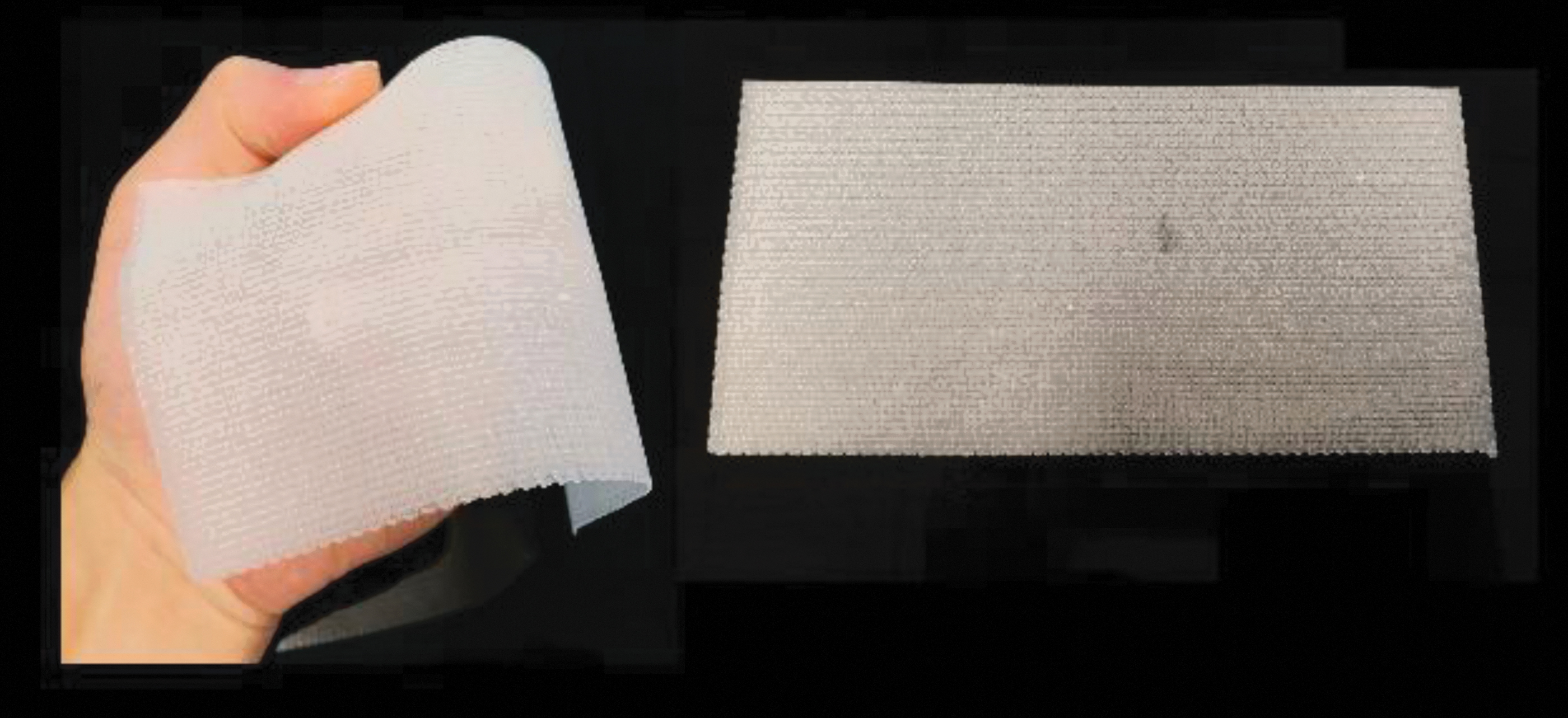
A 3D printed fabric with the material of cellulose composited thermoplastic polyurethane.
Conclusion
FDM 3D printed TPU fabric was examined in this study. Total 15 woven-like fabric structures were applied onto the fabric, by nozzles of different diameters, leading to different layer heights and varying patterns. The 70A flexible TPU material was used to attempt achieving the strength, stretchability, and recovery ability of the fabric.
Limitations
During this study, the limitations of FDM 3D printing as the method to fabricate a fabric were found. The DIY FDM 3D printer was equipped with a direct drive extruder, but flexible material could get entangled inside the extruder due to its very low flexure modulus, causing printing failure. The material with lower hardness, which is more fabric-like, may not be compatible with filament printing. Also, the printing speed was limited by this entangle problem.
If the same mechanism of extrusion is applied for mass production of fabric, the time cost may not be affordable, compared with traditional methods such as knitting and weaving. It is suggested that an FDM 3D printer equipped with pellet extruder can help print lower hardness flexible material for the 3D printed fabric mass production. As same as the most FDM 3D printers, colors of the product are limited by the filament material and the number of extruder head. A fabric with single or mono color may not be widely accepted by fashion industry.
Implications
This study demonstrated 15 possible structures for 3D printed fabric. Those fabrics were subjected to tests and their performance was evaluated in this study. The results as a database could be a reference for designing the structure of an apparel or a garment. Different portions or panels of an apparel may need different performance, such as high stretchability and compression function. The fabric designer may combine different structures into an apparel to achieve visual and functional performance.
Footnotes
Authors' Contributions
Conceptualization, methodology, software, validation, formal analysis, investigation, data curation, writing—original draft, and visualization by Y.-y.W. Conceptualization, methodology, validation, formal analysis, resources, supervision, project administration, and funding acquisition by C.-p.H. Conceptualization, methodology, validation, formal analysis, resources, writing—review and editing, supervision, project administration, and funding acquisition by C.-w.K.
Author Disclosure Statement
No competing financial interests exist.
Funding Information
Authors would like to thank The Hong Kong Polytechnic University for the financial support for this study (Grant number: ZDCC).