
Abstract
In this study, the topology-optimized solid-lattice hybrid structures with variable-density or iso-density are proposed to achieve the structural lightweight and performance requirements. Based on solid isotropic material with penalty topology optimization method, novel optimized structures are designed, including pure solid structure, pure lattice structure, and solid-lattice hybrid structure with iso-density or variable-density. All experimental samples with few 3D-printing defects are fabricated by selective laser sintering additive manufacturing method. Both three-point bending test and finite element simulation are conducted to evaluate the mechanical behaviors, including force-displacement curves and failure modes. Results show that hybrid structure with variable-density lattice has the highest peak force, while the pure lattice fails at the largest displacement which presents high energy absorption. The stress concentrations at the topology-optimized solid region are significantly alleviated by the support of the distributed lattice. It is illustrated that the reasonable lattice distribution around the topology-optimized solid region to increase the structural efficiency is mainly responsible for the obvious improvements. Furthermore, the solid-lattice hybridization-based topology optimization method is applied to the automotive crash beams, and simulations are performed to verify the effectiveness of method. This method provides valuable guidance for lightweight design of high-performance complex structures.
Introduction
Topology optimization is indeed an effective method for achieving structural lightweight design by optimizing the material distribution of a structure.1–4 The goal of topology optimization is to minimize the weight of a structure while still satisfying its performance requirements, such as stiffness, strength, and stability.5,6 By allowing designers to explore a wider range of design possibilities, topology optimization provides greater flexibility in the design process.7,8 However, the resulting optimized structures can be quite complex and difficult to manufacture using traditional methods.9,10 This has limited the practical applications of topology optimization in some fields.
The development of additive manufacturing technologies, such as 3D printing, has made it possible to produce these complex structures with much greater ease, making the use of topology optimization more feasible.11–13 As a result, topology optimization has become an important tool in the development of lightweight structures for various industries, including aerospace and new energy vehicles.14–17 Using topology optimization, designers can create novel structures that are both lightweight and highly efficient, reducing material usage and improving overall performance.
In existing researches, the solid isotropic material with penalty (SIMP) method was the most widely used technique for topology optimization.18–20 It was originally proposed by Bendsøe and has undergone numerous developments. 21 This approach has been successfully applied to various structures and has proven to be effective in producing lightweight designs.22–25 For instance, Wu et al. 26 utilized topology optimization to reduce the volume of spoke plates in the drive gear while increasing the circumferential constraints to create a more visually appealing structure. Similarly, Yunfei et al. 27 optimized the upper arm of a robot using static and dynamic analyses and produced a new arm that is 55.6% lighter than the original, reducing motor load.
Furthermore, Bahramian and Khalkhali 28 improved the bi-directional evolutionary structural optimization algorithm for topology optimization of thin-walled square tubes under the axial crushing load, achieving substantial enhancements in crashworthiness at the expense of a small amount of energy absorption. In addition, Duddeck et al. 29 used the hybrid cellular automata approach to obtain the optimal topology of body crashworthiness under crash conditions. The results indicated that this topology optimization method was used to achieve lightweight designs, as well as improve body performance and safety. To sum up, in the solid topology optimization, the stress concentrations are prone to occur at the tips of hollow structures, which also results in the fatal collapse of overhanging areas.
To address this problem, researchers have introduced lattice structures to enhance the mechanical properties of solid structures.30,31 Lattices consist of interconnected pillars and nodes, forming a truss-like structure in 3D space. 32 This approach not only supports overhanging parts of a solid structure but also acts as a filler core for composite or topologically optimized structures, filling in areas with relative density.33,34 To improve upon this design, a solid-lattice hybrid structure has been proposed. 35 In this type of structure, the lattice helps alleviate stress concentrations in the solid structure, while the solid structure is added into lattice structure to enhance the maximum load-bearing capacity.
Several studies have explored the topology optimization of solid-lattice hybrid structures. Dong et al. 36 used a bidirectional evolutionary structure optimization method to obtain these hybrid structures for wireframes and strut thicknesses. Compared to a pure solid structure, the hybrid structure they designed has 40% higher stiffness and 38% higher critical load. Teimouri et al. 37 further validated the high performance of their designed novel hybrid solid-lattice structures using finite element analysis methods. In their study, the designed hybrid structure reduced the fundamental frequency by 2–10% compared to the pure solid structure, and the specific energy absorbed (SEA) and energy absorption were significantly improved. Xiao et al. 38 proposed a gradient lattice sandwich structure based on multiscale topological optimization. Their study proves that the variable density lattice structure is 54% higher than the equal density lattice structure in terms of critical load under a certain volume fraction constraint. Liu et al. proposed a multivariate cut level set method for topology optimization of honeycomb structures, which provides greater freedom in the design of lattice structures.39,40
Although the design of lattice in hybrid structure was primarily based on iso-density distribution, recent reports have shown that the lattice structure with variable density performs better in improving the efficiency of lattice struts than the iso-density structure.41–43 Therefore, it is necessary to combine the variable density lattice design and topology optimization method to enhance the mechanical properties of solid-lattice hybrid structures, making the material distribution more reasonable.
In this study, a more efficient method for the design of lightweight solid-lattice hybrid structures is proposed. The solid-lattice hybrid structure is obtained by combining the basic topology optimization method with lattice optimization. In “Design, Methods, and Analysis” Section, the method and design process of the method are introduced with a three-point bending beam as an example. The additive manufacturing process of the designed structure is also introduced, and three-point bending experiments and simulation are conducted. In “Experimental and Simulated Results” Section, the experimental and simulation results of three-point bending are analyzed and discussed, and the present design approach is summarized. In “Case Study” Section, the design method is applied to an automotive crash beam to further verify the effectiveness of the method. Finally, some important conclusions are summarized in “Conclusions” Section.
Design, Methods, and Analysis
Figure 1 shows the design flow of the solid-lattice hybrid structure. It can be roughly divided into two phases. In the initial stage of the design, the initial model is statically analyzed. Based on the obtained stress distribution, the topology optimization and lattice optimization are performed, respectively, and lattice optimization yields a pure lattice structure. The structure obtained by topology optimization is geometrically reconstructed to make it as regular as possible to obtain a pure solid structure. The second stage is the design and filling of the lattice structure, including lattice structures with variable-density and iso-density. Then, the connectivity of the lattice structure and solid structure is checked. In this section, we will discuss the design process of the four structures in detail. After that, the sample preparation is described. The mechanical properties of the designed structures are verified by three-point bending tests and simulations, and the four structures are compared. Their displacement-load curves are discussed, and the experimental results are analyzed. Finally, this design is summarized and discussed.

Flow chart of solid-lattice hybrid structure design.
Topology optimization design
The density-based optimization method is executed based on the density of each element in the model. It uses the SIMP, where its density value is not continuously varying and can only be 0 or 1. There are limitations and requirements associated with performing density-based optimization analysis. The method of moving asymptotes (MMA) has been extended to give the Sequential Convex Programming (SCP) method.44–47 In the SCP method, it is required to derive all functions in the topological optimization model. MMA represents a nonlinear programming algorithm that first solves a series of convex molecular problems to approximate the solution of the optimization problem. These problems have such a special structure that this method is highly efficient in solving topological optimization problems. By extending MMA, the SCP method has been greatly improved in the problem of optimal convergence. The density-based optimization problem can be solved by the optimality criterion method with a simple compliance objective using volume or mass constraints. It is an iterative solver. 48
In this study, a density-based topology optimization method is used. Minimizing structural compliance is the objective function of topology optimization. The mathematical model is as follows
8
:
Subject to:
where f is the objective function, ρ is the vector of the density design variables, and hj and gi are constraint functions. C denotes the compliance, F is the load vector, K is the global stiffness matrix, and U is the displacement vector.
Topology optimization for the loading conditions of the three-point bending experiment, with the initial model consisting of the top and bottom panels and the middle core. The boundary conditions of the model are shown in Figure 2a. Figure 2b shows the dimensional configuration of the initial model. In this study, the length (l), width (w), and thickness (h) of the beam are 60, 10, and 20 mm, respectively. Top and bottom panel thickness (ha) is 2 mm. The upper and lower panels are nondesigned areas and are only optimized for the middle sandwich section. The span (la) between the two supports is set as 50 mm, and 100 N load is uniformly distributed on the centerline of the upper surface of the upper plate. The target volume fraction (vf) for topology optimization is set to 30%.
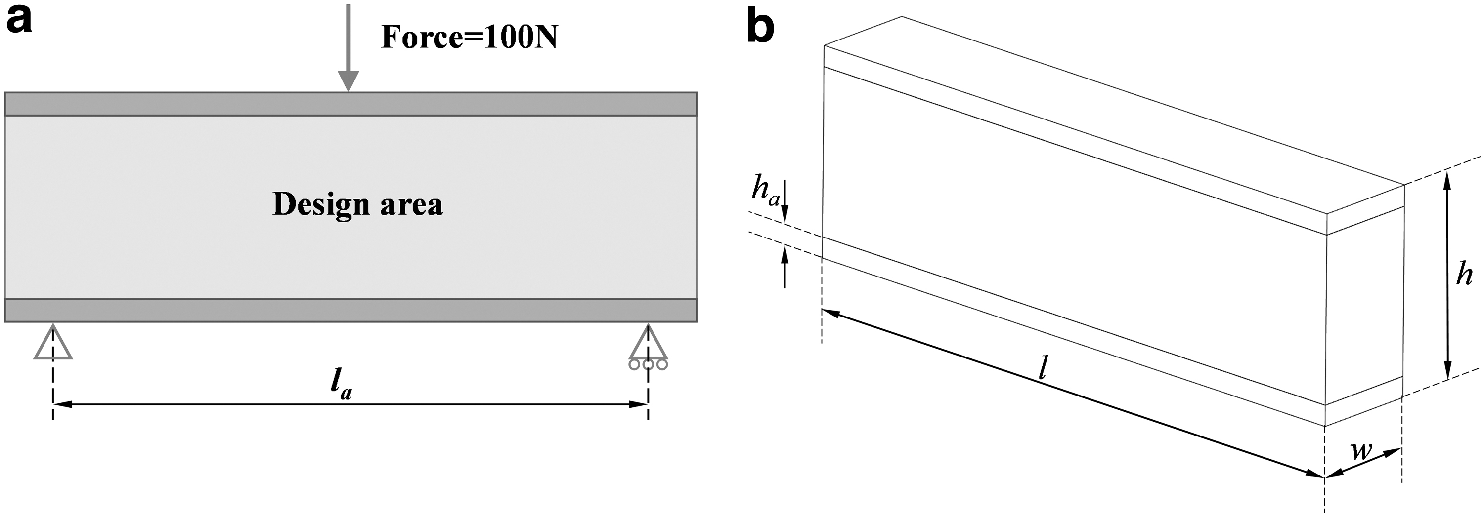
Initial model diagram:
Optimization of solid and lattice structure
Based on the above theory, the initial model is topologically optimized. At the same time, the manufacturing constraints are added to facilitate the subsequent processing of the model. The minimum cell size is set, which eliminates the fine force transfer paths in the optimization results and ensures that the minimum scale of the structure is larger than the minimum member size to get a more uniform material distribution.
A front view of the topology structure after topology optimization is shown in Figure 3a, with a bridge-like geometry. In this case, the surface of the structure is uneven and extremely irregular, which is not conducive to manufacturing. Therefore, the geometry needs to be reconstructed. The reconstructed geometry is shown in Figure 3b, which we call an optimized solid structure. The volume fraction of the reconstructed geometry was calculated to be 46.1%.
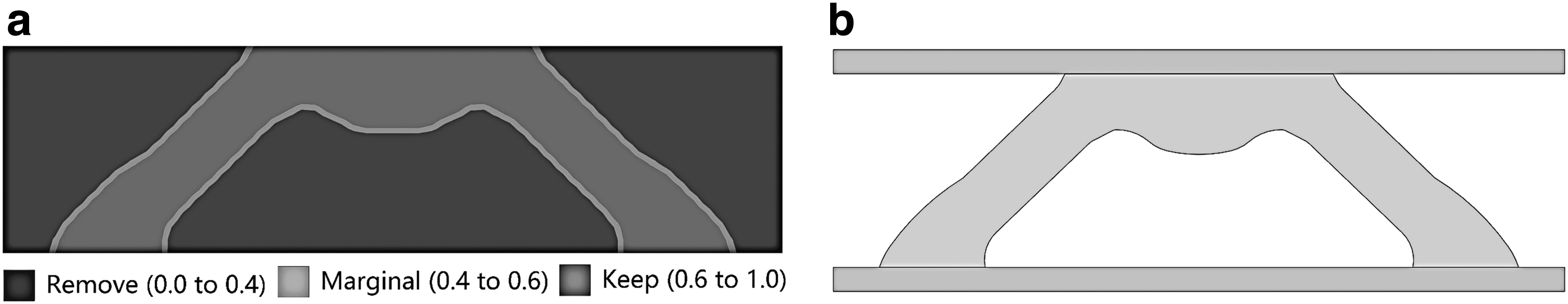
Topology optimization of the initial solid model.
The lattice structures are widely used in structural light weighting due to their excellent properties of high specific strength and stiffness, as well as high energy absorption. The lattice structures can be divided into lattice structures with variable-density and iso-density in terms of the uniformity of the lattice distribution. Compared to the lattice structure with iso-density, the lattice structure with variable-density exhibits superior mechanical properties. 49 Because it has a more rational material distribution. The lattice optimization method enables it to calculate the optimal variable density lattice distribution in geometric structures. In this study, the lattice optimization is performed for the initial model.
In the lattice optimization, the body-centered cubic cell was chosen as the base lattice. The minimum and maximum densities were set to 0.2 and 0.8, respectively, and the cell size was 5 mm. The lattice optimization process is shown in Figure 4a, where the colors represent the size of strut, and the blue and red represent the smallest and the largest size. Setting the target volume fraction too small will result in a small minimum strut diameter. Taking into account the additive manufacturing process and the 3D-printing accuracy (±0.2 mm), the minimum strut diameter dmin should be no less than 0.5 mm. In this study, the target volume fraction is set to 40%. Figure 4b and c shows the optimized lattice structure with variable-density, where the minimum strut diameter was measured to be dmin = 0.9 mm. Finally, the volume of the optimized lattice structure is 54% of the original volume.

Optimization of solid-lattice hybrid structure
To make up for the deficiencies in the solid and lattice structures, this study proposes to fill the lattice structure into the blank area of solid structure to form a solid-lattice hybrid structure. The generation of the hybrid structure takes place in two broad steps. First, the configuration of the solid part was designed based on the previous topology optimization, as shown in “Optimization of solid and lattice structure” section. Second, the designed lattice structures with iso-density and variable-density are filled in the blank area inside the solid part, that is, the area with low-density during topology optimization.
After obtaining a solid part by the topology optimization, it first needs to fill all the blank areas with lattices. This part can be directly transformed into a lattice structure with iso-density, which forms a solid-lattice hybrid structure with iso-density. As shown in “Optimization of solid and lattice structure” Section, the lattice optimization is similarly performed on the optimized region to obtain the lattice structure with variable-density, and then, it is integrated with the solid part to obtain the solid-lattice hybrid structure with variable-density. The lattice section still uses a body-centered cubic cell with a single cell size of 5 mm. Here again, the minimum strut diameter dmin of the lattice section is controlled. The above optimization process is shown in Figure 5.
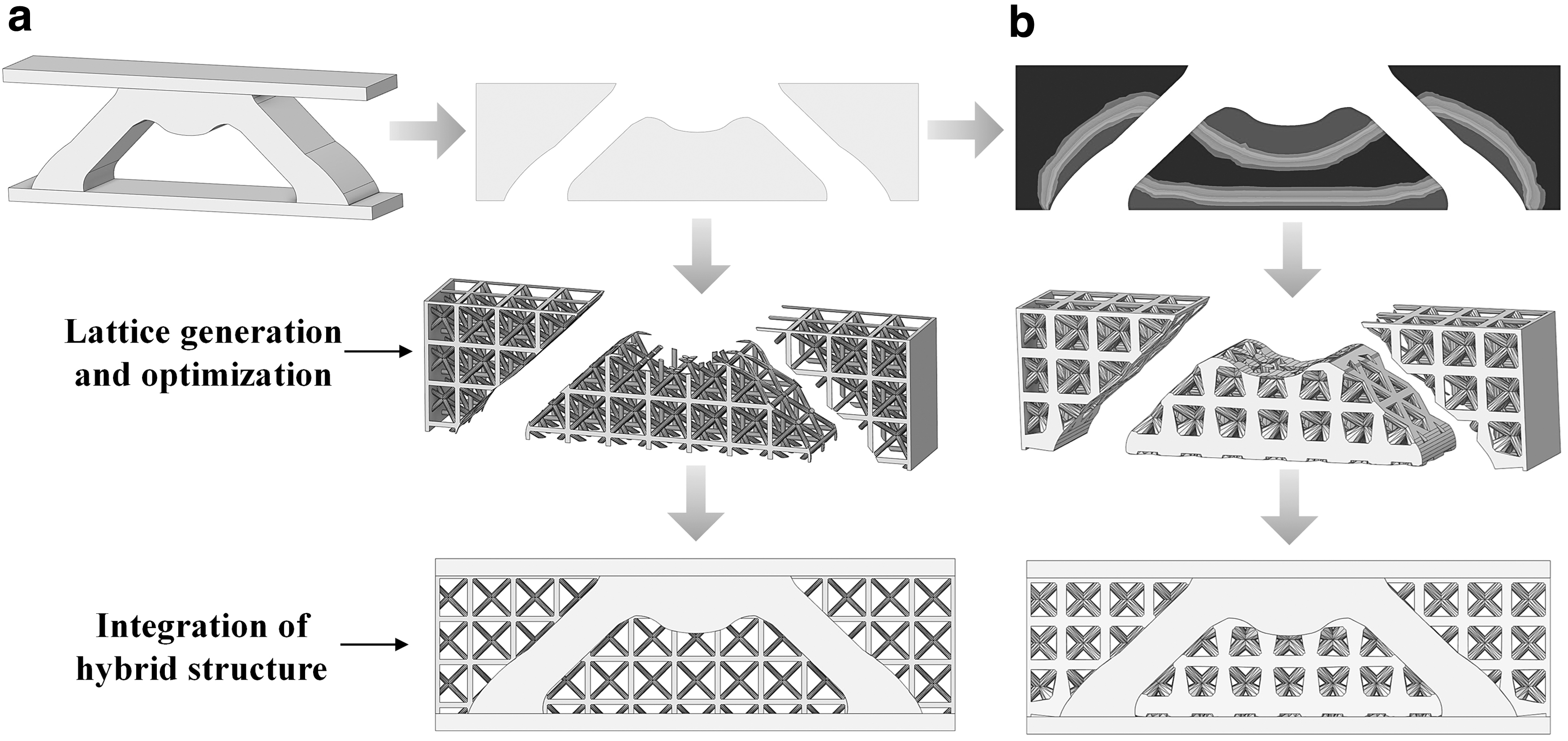
Design process of solid-lattice hybrid structure.
Modeling the complicated solid-lattice hybrid structure has always been a difficult task, because of the connection part between the lattice structure and the solid structure, where many tips may be present. These tips are likely to exist independently from the lattice structure or lead to a situation where the finite element mesh is difficult to delineate. This phenomenon is particularly severe in the solid-lattice hybrid structure with variable-density. In this case, the density threshold needs to be adjusted to change the geometry of the lattice until the lattice structure can meet the requirements of subsequent work.
Fabrication by 3D printing and tests
Due to their extremely complex structure, it is difficult to ensure the manufacturing accuracy of hybrid structures using traditional manufacturing processes.50,51 In this study, the experimental samples were fabricated by selective laser sintering (SLS) additive manufacturing technology, and nylon PA2200 powder was selected as the base material. The materials have excellent strength, high stiffness, high energy absorption, and processability. The EOS Formiga P110 3D printer was used for processing a 30 W CO2 laser and a Scanlab high-performance galvanometer. Table 1 shows the basic parameters, including materials, equipment, and printing.
Basic Parameters, Including Materials, Equipment, and Printing
The additive manufacturing enables unsupported 3D printing, which is advantageous for the processing of complex structures such as lattice structures. For the solid structures, the machining requirements can be fully met. In contrast, the other three structures may have partial defects. For example, there may be small tips at the connection points between the lattice and the solid, smaller strut diameters at the front and rear sides, and so on, which may lead to printing discontinuities or even collapse. To meet the minimum dimensional requirements for machining, it is not only necessary to control the dmin to no less than 0.3 mm but also to thicken the aforementioned parts. Some of the parameters printed are also shown in Table 1.
Figure 6a–d shows the macroscopic views of the four samples, and the density variation of lattice can be clearly seen in Figure 6b and d. Figure 6e and f shows that the lattice structure is well connected to the solid structure by the SLS with the reasonable process parameters. However, some printing defects with visible particles at some struts and nodes are still observed in Figure 6e and f, including redundant printing, gap defects, and material accumulation. The main reason for producing these defects is due to the too small size and high density in lattice, but this is within the experimentally acceptable range.

In this study, the bending deformation behaviors of the samples are investigated through three-point bending experiments. The diameter of loading body and supporters is 10 mm. The span between the rigid supporters is set at 50 mm. The WANCE electronic universal testing machine was used to test the mechanical properties of samples. The loading speed was set to 5 mm/min, and the corresponding displacement and load were recorded until the sample was damaged.
Finite element modeling
To verify the mechanical properties of the designed structure using this novel method, a three-point bending finite element simulation was performed, and the finite element model was established. The boundary conditions are the same as the three-point bending experiments in “Experimental analysis” Section. The finite element model was built in the commercial software ABAQUS/Explicit. The plastic material properties and experimental parameters in the simulations are shown in “Fabrication by 3D-printing and tests” Section. The indenter and support are set as rigid bodies. A General Contact with a friction coefficient of 0.2 is set among all contact surfaces to simulate the contact behaviors in the three-point bending test. A linear hexahedral (C3D8R) finite element mesh is used for the solid part, and a quadratic tetrahedral (C3D10M) finite element mesh is used for the lattice part. The quasi-static loading velocity is established, and then the bending load-displacement curves are recorded and analyzed.
Experimental and Simulated Results
Experimental analysis
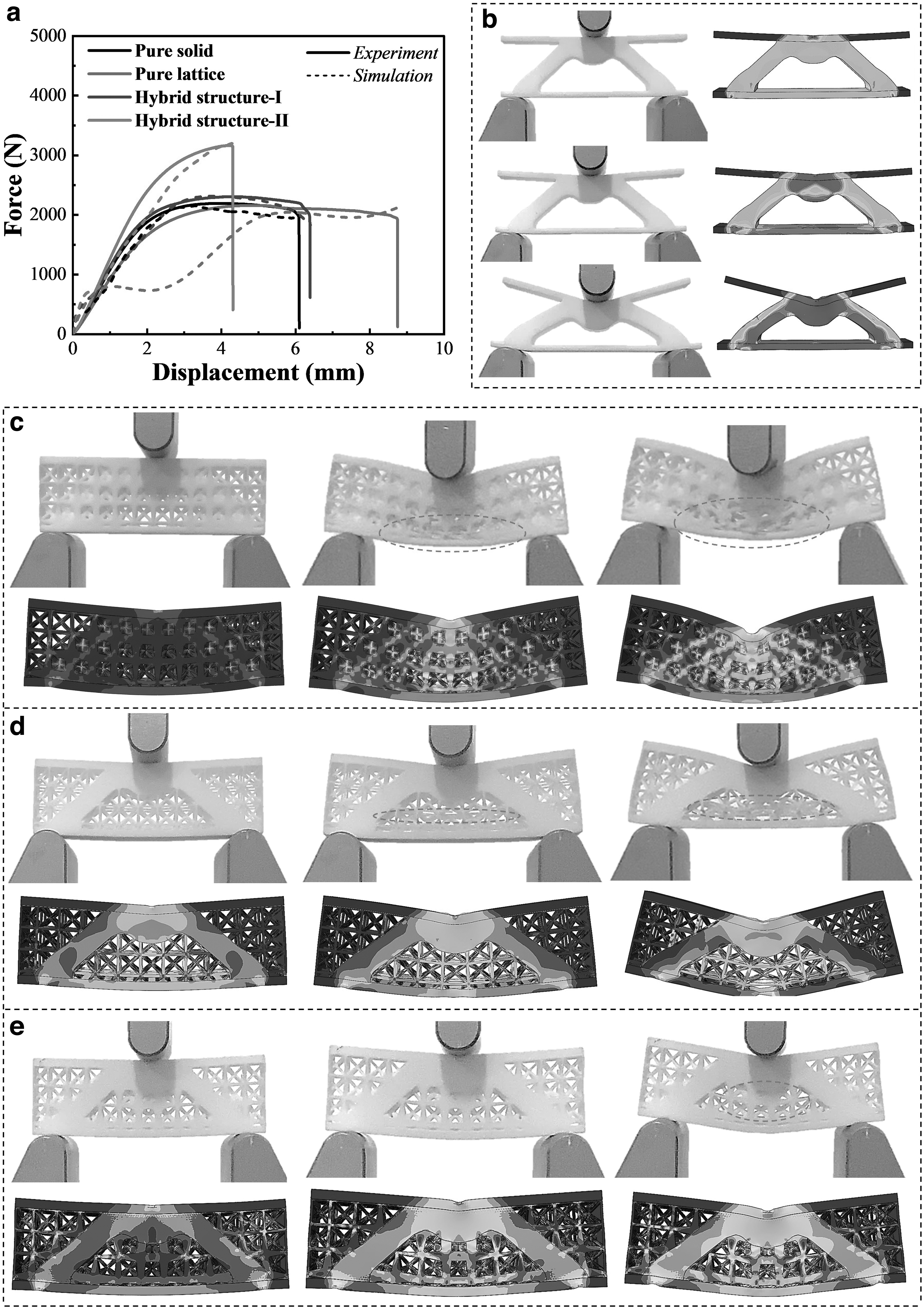
Figure 7 shows the experimental and simulated results, including bending displacement-load curves and bending failure process. The corresponding maximum displacement (δmax) and maximum load (Fmax) are given in Table 2. It can be seen from Figure 7a that the bending stiffness of the solid-lattice hybrid structure with variable-density is much higher compared with the other three structures. In addition, the pure lattice structure exhibits the maximum displacement and minimum load, indicating that it has the highest bending energy absorption but the lowest bending capacity. Kim et al. 52 also reached similar conclusions in their research. The critical bending loads of both hybrid structures are significantly higher than those of the pure solid structure and pure lattice structure, which proves that the filled lattice structure can effectively increase the critical loads. This may be due to a reasonable material distribution by topological optimization. Among them, the effect of hybrid structure with iso-density is also shown in the study of Xiao et al., 38 but the study of hybrid structure with variable density is lacking.
Comparison of Experimental Results for all Samples
δmax, maximum displacement; EA, energy absorption; Fmax, maximum load; SEA, specific energy absorption.
Moreover, it is shown that the hybrid structure with variable-density lattice performs better than that with iso-density lattice in terms of the maximum bending load, which also displays the superiority of variable-density. The advantages of lattice structure with variable density are discussed by Xiao et al. 40 However, the effect of variable density lattice structure in hybrid structures has not been investigated. By comparing all structures, it is suggested that the designs of lattice and solid-lattice structures have unique advantages to improve a certain bending property of solid structure, such as maximum bending load, deformation displacement, or energy absorption. Thus, a conclusion can be drawn that optimizing material distribution based on stress distribution can simultaneously maximize material utilization and improve the specified structural performances.
As shown in Figure 7b–e, the critical failure states for each structure are observed. For the pure solid structure, due to lack of support, the top region undergoes a large amount of bending deformation. The bending load is mainly carried by the optimized solid region and the bottom region. For the pure lattice structure, the lattice cells with the low-density region located at the bottom are deformed and buckled first. As the bending displacement increases, some struts of the lattice cells present the fracture and accumulation. At the end of bending, all of lattice cells around the low-density region are severely deformed or even destroyed. In the study by Dong et al. 36 on solid-lattice hybrid structures with additive manufacturing, similar damage modes also exist in pure lattice structures. Compared to the pure lattice structure, the solid-lattice hybrid structure with iso-density has a similar damage pattern.
This design method is effective at reducing the burden on the optimized solid region by providing a high structural efficiency. The displacements and critical loads of the equal-density solid-lattice hybrid structure have similar effects to other studies.38,52 Furthermore, it can be observed from Figure 7e that the solid-lattice hybrid structure with variable-density is the least deformed among all structures before the global bending failure. At this time, overall lattice structure remains relatively intact until the critical state is shown. This is due to the fact that the solid-lattice hybrid structure with variable-density has a more effective distribution of lattice density to support the main stressed regions. Therefore, the solid-lattice hybrid structure with variable-density has the largest critical bending load. However, an obvious brittle fracture is presented, which is unfavorable for the sustained energy absorption.
To evaluate the energy-absorption capacity, the total energy absorption is obtained by numerically integrating the bending load-displacement curve in Figure 7a, which can be expressed as:
where δ is the displacement, and F(x) is the corresponding load.
The SEA per unit mass is a key indicator to distinguish the energy-absorption capacity of different structures, defined as
53
:
where M is the total mass of the structure. The higher the value of SEA, the higher the energy-absorption capacity of the structure.
Table 2 shows the corresponding energy absorption (EA) and SEA. It is worth noting that the pure lattice structure exhibits the highest EA and SEA, which can be explained by the fact that the pure lattice structure has the largest critical displacement. Although the solid-lattice hybrid structure with variable-density has the highest critical load, its critical displacement is much smaller than the other three. Therefore, the solid-lattice hybrid structure with variable-density has the lowest energy-absorption capacity, which shows a phenomenon of a tough dilemma.
For another, the solid-lattice hybrid structure with iso-density has lower maximum bending load but higher EA and SEA than that with variable-density. The findings from Table 2 reveal that the hybrid structure with variable-density exhibits superior load carrying capacity per unit mass in comparison to other structures. This effectively underscores the benefits of rational material distribution, as it leads to a more efficient use of materials and enhances structural performance. By optimizing the placement of materials within the structure, the hybrid design is able to achieve greater strength and stability while minimizing weight, thereby maximizing its load-bearing capabilities. By full considerations related to load bearing and EA, it is indicated that the solid-lattice hybrid structure with iso-density has outstanding comprehensive bending properties.
Simulation analysis
The experimental and simulated bending force-displacement curves are compared in Figure 7a. It is shown that the simulated results, including peak force and failure force, are in general agreement with the experimental results with little difference for pure solid, hybrid structure-I and -II. However, it is observed that the simulated force for pure lattice with variable-density is much lower than the experimental force around 1–5 mm.
These differences observed between experiment and simulation are mainly because some printing defect, such as porosity and accumulation, and others, were produced during the printing process, as presented in Figure 6. In detail, the printed gaps between some struts are too small which is limited by the SLS printing process, leading to many denser cells in the experimental pure lattice structure. Therefore, there are many redundant printing defects and material accumulation in their samples. That is, some of the strut diameters and nodes in actual samples are slightly larger in the established printing models. In simulation, the local breakage or buckling of struts occurs in the pure lattice structure, resulting in the falling of force at 1–5 mm. In contrast, the experimental force is higher due to 3D-printing defects.
Regarding the simulated stress and failure diagram, it is observed from Figure 7b that the stress concentration is initiated in the contact point between the loading body and the pure solid structure. Then, the high stress concentrations cover the entire bearing area (optimized region and bottom region), which severely threatens the safety of this structure. For the pure lattice structure, it is shown from Figure 7c that the stress concentrations are significantly alleviated by the lattice cells with variable-density but the local lattice cells obviously fail. Compared to the pure lattice structure, it is found from Figure 7d that the hybrid structure-I with iso-density shows more uniform stress distribution in lattice cells. With the help of lattice, the pure solid region is effectively supported and its stress decreases.
By comparing the experiment and simulation, similar failure of lattice and obvious necking phenomenon occurring in the materials at the bottom region are presented. And from the simulation results of other studied hybrid structures, there are still some stress concentrations.38,39,53 For the hybrid structure-II with variable-density, it is indicated from Figure 7e that the lattice cells in the right and left regions can bear a certain force, which is different from others. This illustrates that more reasonable lattice distributions are obtained by this hybridization design method. Furthermore, it is also observed that the overall deformation is smaller for hybrid structure-II due to the higher local lattice density. When the critical failure state is satisfied, the lattice cells in low-density region fail. Thus, the hybrid structure-II with variable-density has the highest capacity to resist the bending force.
The size effect of lattice structures is a critical factor that significantly impacts the mechanical properties of such structures. To gain insights into this phenomenon, a parametric study is conducted where the rod diameter of the unit cell is varied while keeping other parameters constant. The objective is to investigate how changes in the rod diameter affect the load-bearing capacity and mass of the hybrid structure-I with iso-density. Utilizing the ABAQUS/Explicit platform, displacement load variation simulations are performed for different lattice cell rod diameters. The analysis focused on three specific rod diameters: 0.5, 0.6, and 0.7 mm. The results obtained from these simulations are depicted in Figure 8, which highlights the relationship between the rod diameter and the load-carrying capacity of the hybrid structure-I with iso-density.

Displacement load curves of solid-lattice hybrid structure-I with iso-density for different microstructure sizes.
It is observed that as the lattice structure rod diameter increased, the load-carrying capacity of the hybrid structure-I with iso-density also increased. However, this improvement in load-bearing capacity came at the expense of an increase in mass. Furthermore, during the initial stages of loading, there was not much difference between the performance of the structures with different rod diameters. As the displacement continued to increase, it became apparent that the hybrid structure-I with iso-density at 0.6 and 0.7 mm cell-rod diameters exhibited a more stable behavior compared to the structure with a 0.5 mm rod diameter, which showed a decreasing trend. These findings provide valuable insights into the size effect of lattice structures and can be used to optimize their design for specific applications.
Discussion on design method
The mechanical properties of the four designed structures have been analyzed experimentally and numerically. It is indicated that each structure has its advantage for the bending resistance. For the pure lattice structure, its peak force is similar with the pure solid structure. However, this type of structure has the largest failure displacement to absorb more energy absorption with lighter weight, and thereby, it has great application prospects such as energy absorber. 54
For the solid-lattice hybrid structure-I and -II, they present obvious differences in peak force and failure displacement. Herein, the hybrid structure-I can improve the peak force (5.1%) and failure displacement, which presents high comprehensive properties. 38 However, an improvement of 57.8% in peak force over the pure solid structure is recorded for the hybrid structure-II but the failure displacement decreases greatly. Based on the curve, it is illustrated that the solid-lattice hybrid structure with variable-density displays a brittle failure characteristic with high carrying capacity. Hence, the hybrid structure-II is the best choice to be used for the antibending application. 41 In summary, the lattice structure with variable-density and the hybrid structure-I and -II designed in this study have excellent performances and their respective advantages in different application fields. The design method coupled with solid-lattice hybridization and topology optimization has great advantages over the traditional topology optimization method. 49
Case Study
In this section, the proposed design method is applied to automotive crashworthiness design. Four different lattice structures are designed by SIMP method at ANSYS workbench to replace the solid internal volume of the automotive crash beam. The topology optimization design process for automotive crash beams is presented, and the mechanical properties of the proposed structure are evaluated by a three-point bending numerical simulation method.
Topology optimization of bumper beam
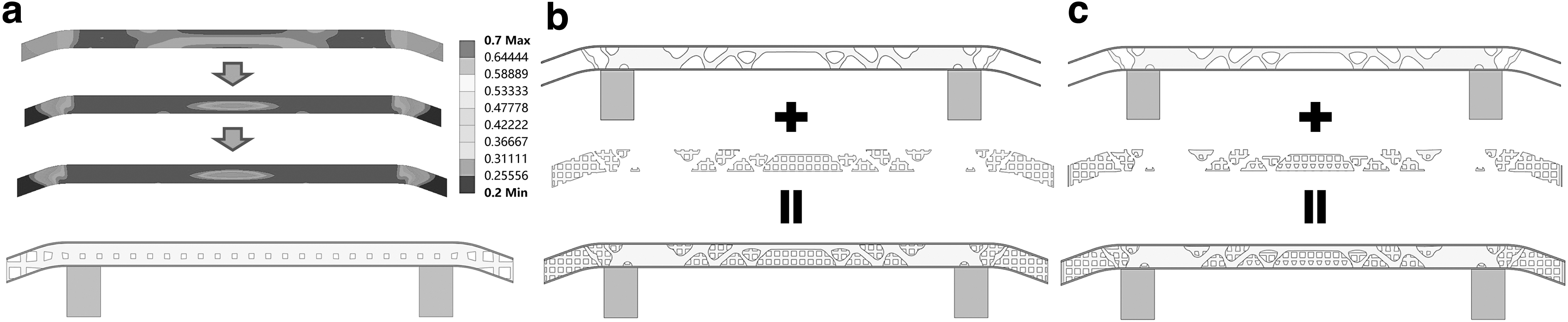
In this section, the SIMP method is used to optimize the middle domain of the automotive crash beam. The designed benchmark beam shown in Figure 9a is loaded with a uniform load. The dimensions of the beam are 300 mm × 15 mm × 20 mm. A 3000 N load is uniformly distributed on the upper surface and the energy-absorbing box is fixedly supported, as shown in Figure 9a, optimized only for the middle area, the Young's modulus of the base material is assumed to be E = 200 GPa, and the Poisson's ratio is μ = 0.3. The objective of the topology optimization problem is to find the minimum structural compliance for a certain percentage of conditions. The solution is based on the SIMP method in ANSYS workbench. The material removal process and the final geometric reconstruction results are shown in Figure 9b. Similarly, we refer to the final obtained structure as the pure solid structure.

Topology optimization of automotive bumper beam:
Design of solid-lattice bumper beam
In the case of this study, lattice optimization is first performed, as shown in “Fabrication by 3D-printing and tests” Section. The optimized boundary conditions are shown in Figure 9a. The cubic lattice was chosen as the base lattice due to the more complex model and to facilitate subsequent simulation analysis. Taking into account the design requirements and the additive manufacturing process constraints, the upper and lower lattice density limits are set to 0.7 and 0.2, respectively, and the cell size is set to 10 mm. The objective of the optimization problem remains to find the minimum compliance at a given percentage. The variation of the lattice density during the lattice optimization is illustrated in Figure 10a. Figure 10b shows the final generated pure lattice structure, with a total of 60 lattices generated in the optimized region. The location of the smallest strut diameter of the structure is on the left and right side, ∼3 mm, which meets the manufacturing requirements.
Design of bumper beam:
The generation of the hybrid structure is performed in two steps. First, a solid filling of the removed material area is performed based on the solid structure obtained from the previous topology optimization. Second, this solid part is optimized, and the resulting dotted structure is filled into the blank area. The solid part can be directly converted to a lattice structure with iso-density to obtain the solid-lattice hybrid structure with iso-density. Lattice optimization is performed on these regions to obtain lattice structure with variable density that meets the design requirements and manufacturing constraints. These lattice structures are filled into the solid structure, and the contact area between the lattice structure and the solid structure is checked to obtain the solid-lattice hybrid structure with variable-density.
The body-centered cubic lattice cell with a single cell size of 5 mm was chosen to fill all the empty spaces inside the solid structure. The two hybrid structures are shown in Figure 10b and c. The strut diameter of the solid-lattice hybrid structure with iso-density was measured to be ∼1.9 mm, with all cells of the same size. The optimization results show that the solid-lattice hybrid structure with variable-density shows a trend of decreasing density from the middle to the sides. The smallest strut diameters are on the left and right sides, measured at ∼1.5 mm, so that both hybrid structures meet the manufacturing requirements. At this point, the two hybrid structures are approximately the same volume as the pure lattice structure. Moreover, the two hybrid structures have good connectivity with the solid structure, which provides a favorable condition for the simulation.
Finite element failure analysis
To evaluate the mechanical properties of all the solid-lattice hybrid structures and taking into account the computational effort, a three-point bending finite element simulation was performed for each structure. In this study, the width of the indenter bottom surface was set to 26 mm. The energy-absorbing box is used as a fixed support, and it is set as a rigid body to prevent the box from deformation. The span between the supports is 208.65 mm, the displacement of the indenter is set to 10 mm, and the total duration is 1 s. The material is a structural steel with a yield strength of 250 MPa. A linear hexahedral finite element mesh (C3D8R) is used for the rigid body and the indenter, and a quadratic tetrahedral finite element mesh (C3D10M) is used for the rest. The mesh size of the pure solid structure and the pure lattice structure is 1 mm, and in the hybrid structure, the local complex area can be set to 0.8 mm or even smaller.
Figure 11 shows the structural deformation and the stress distribution of four structures. It can be seen from Figure 11a that the average value of the branched chain reaction force is higher for both the pure lattice structure and the two hybridized structures than for the pure solid structure. Compared with the solid-lattice hybrid structure and the lattice structure, the pure solid structure is subjected to lower and stable flexural damage loads within the crushing distance. The pure lattice structure is the most unstable in the deformation process, and the peak structural load oscillates violently at the beginning, and its stable load approximates to that of the solid-lattice hybrid structure with iso-density. The solid-lattice hybrid structure with variable density exhibits the maximum average load, which is also the best performance. Compared to the pure solid structure, it has 17% more volume and 100.27% more average load. The average load of the pure lattice structure and the solid-lattice hybrid structure with iso-density is increased by 67.33% and 73.09%, respectively, compared to the pure solid structure. It is noteworthy that the pure lattice structure has similar volume to the two hybrid structures.
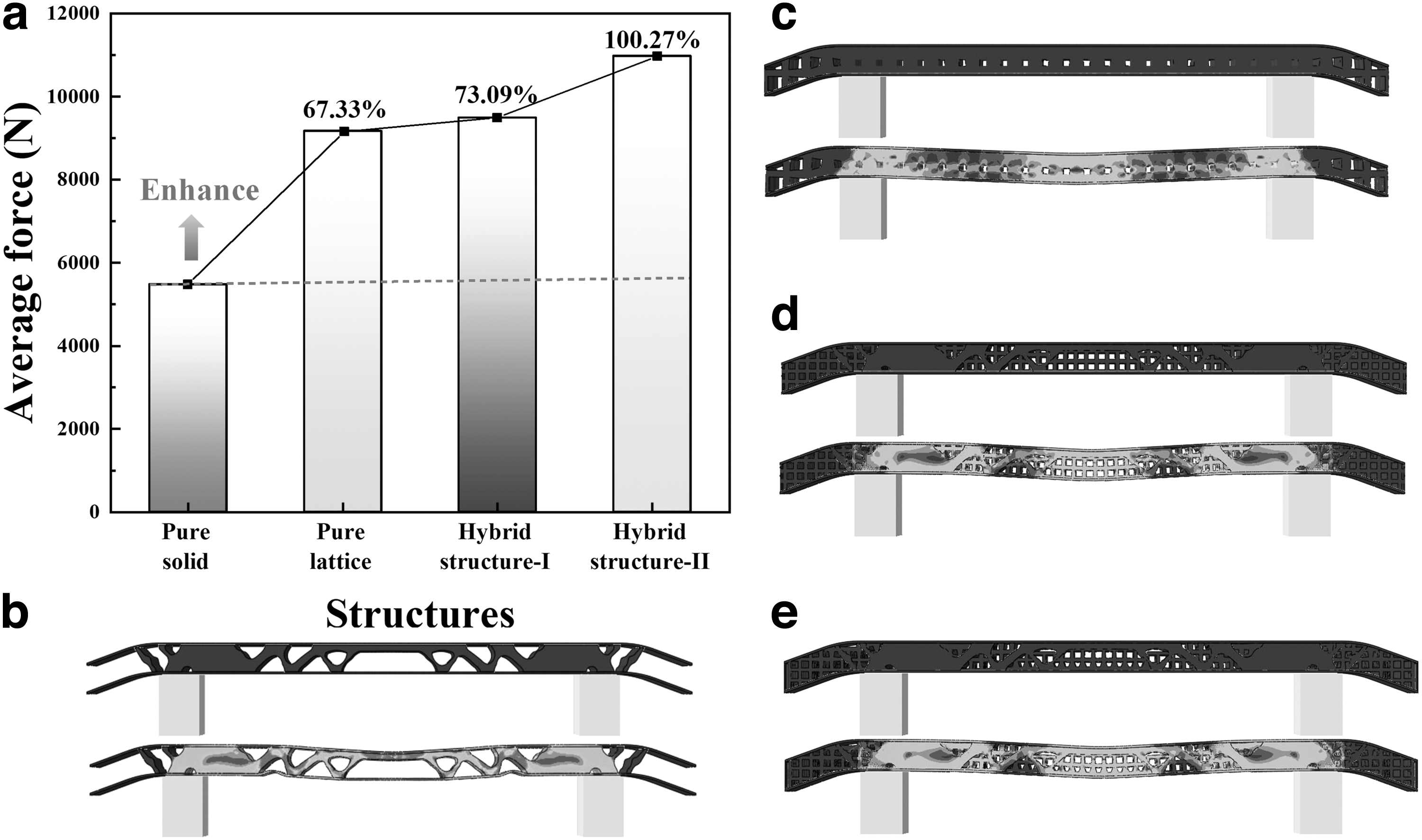
The above results show that the solid-lattice hybrid structure with variable density has the best load carrying capacity and stiffness among the four types of structures. From Figure 11b, it is observed that the pure solid structure exhibits obvious stress concentrations in some regions. However, the pure lattice and lattice with iso-density and variable-density in hybrid structure can reduce the stress concentrations, especially solid-lattice structure with variable-density.
Conclusions
In this study, an efficient method for solid-lattice hybrid structures is proposed by combining topology optimization method. First, pure solid structure and pure lattice structure are obtained based on basic topology optimization and lattice optimization, respectively. Second, the iso-density lattice structure is filled into the pure solid structure to obtain the solid-lattice hybrid structure with iso-density. Finally, the optimized variable-density lattice structure is filled into the pure solid structure to obtain the solid-lattice hybrid structure with variable-density. The effectiveness of the proposed method is verified using the designed four 3-point bending beam structures by experimental and simulation methods.
The simulated and experimental structures show that the variable-density solid-lattice hybrid structure has the most excellent mechanical properties. Among them, the critical displacement of the variable density solid-lattice hybrid structure is 44.5% higher compared with the pure solid structure. The pure lattice structure has the best energy absorption capacity with about twice the value of the pure solid structure. Compared with the pure solid structure, the energy absorption of the iso-density solid-lattice hybrid structure is improved by 10%. From the experiments, it can be seen that both pure and hybrid lattice structures fail from the middle lattice. In addition, this design and optimization method is applied to the design of automotive crash beams, and the simulation results further illustrate the advantages of hybrid structures, especially solid-lattice hybrid structure with variable density. In the future, other practical applications will be further developed and the manufacturability of the structure will be improved.
Data Availability Statement
The optimization model used to generate the topology optimization results and the finite element model used to reproduce the flexural behaviors of hybrid structures. The data are provided in the results of the examples in the form of pictures and tables.
Footnotes
Authors' Contributions
H.J.: Conceptualization, funding acquisition, project administration, supervision, writing—review and editing. X.L.: Data curation, investigation, methodology, validation, writing—original draft, visualization. Z.L.: Investigation, resources, writing—review and editing. Y.R.: Investigation, resources, writing—review and editing.
Author Disclosure Statement
The author(s) declared no conflicts of interest. The authors declare that the work described was original research that has not been published previously and not under consideration for publication elsewhere, in whole or in part.
Funding Information
H.J. gratefully acknowledges the financial supports from China Postdoctoral Science Foundation (First-Class Support) (No. 2022M720132), Guangdong Basic and Applied Basic Research Foundation (No. 2022A1515110342, No. 2023A1515012177), Open Foundation of State Key Laboratory of Advanced Design and Manufacturing for Vehicle Body (No. 32115004), and Scientific Research Funds for High-level Talents of China University of Geoscience (Wuhan) (No. 162301212652).