
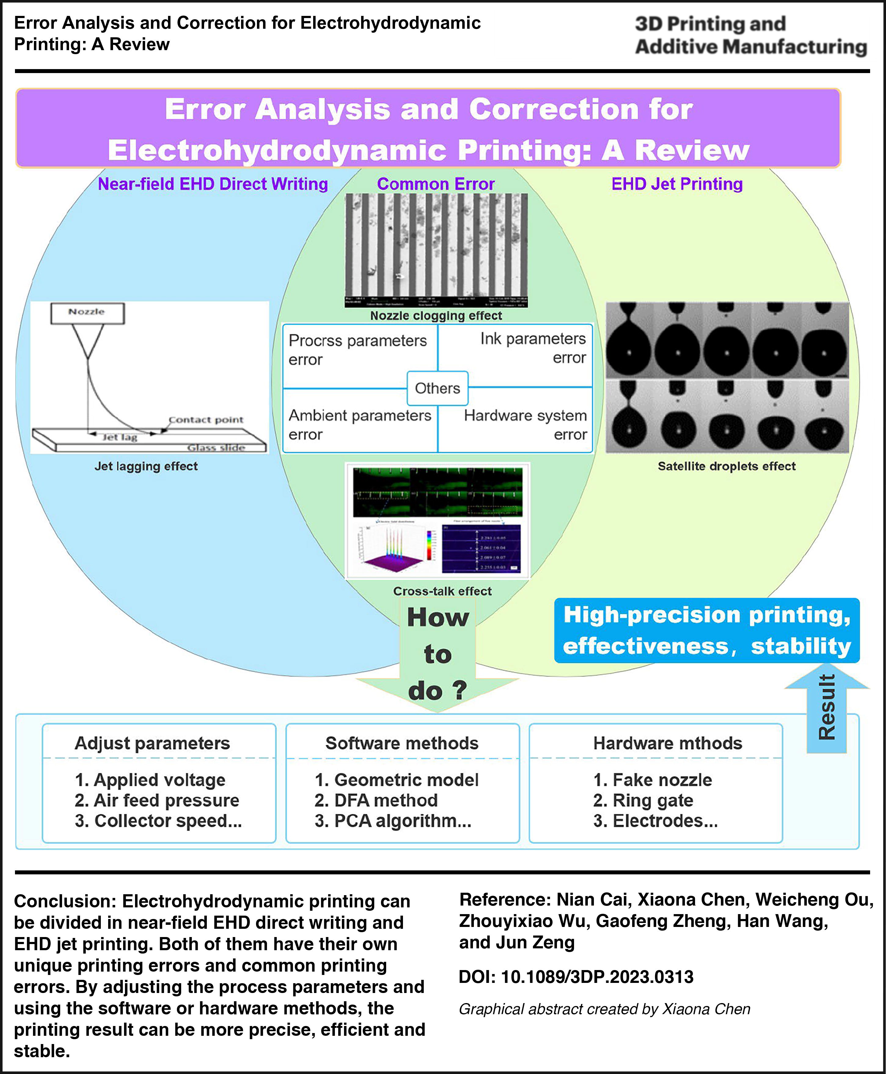
Abstract
Electrohydrodynamic (EHD) technology is renowned for its significant advantages in high resolution and micro-nanoscale printing, demonstrating an immense potential in the development of micro-nano devices. During the printing process, it is inevitably influenced by different interferences, which result in printing errors that influence its printing precision. This article summarizes several research topics on printing errors of EHD printing technology, involving the sources, and correction of different types of printing errors. First, the induced factors of printing errors are summarized in details, which are used to categorize the error correction methods. Then, the existing correction methods are comprehensively summarized and analyzed according to the types of printing errors. Finally, the conclusions are provided, involving some potential research topics.
Introduction
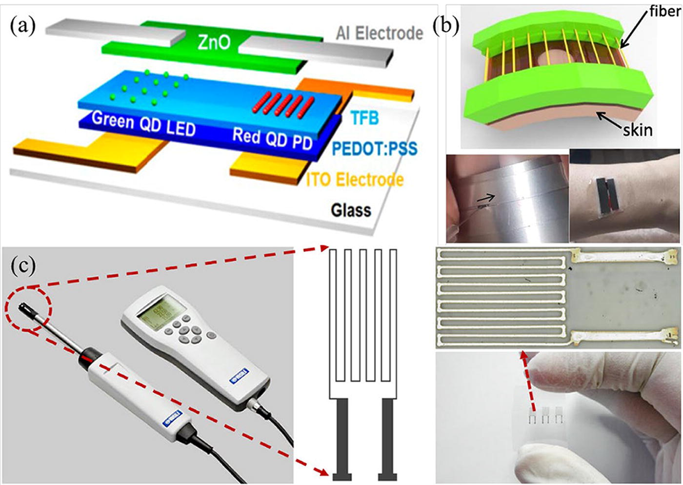
Electrohydrodynamic (EHD) printing technology is a noncontact high-resolution patterning method, which has the advantages of high precision, simple printing process, high compatibility, low cost, and high efficiency.1,2 Owing to these advantages, it has been widely applied in various fields, such as biomedicines application,3–5 electronics devices,6–10 functional sensors,11–13 and micro-fluidic devices,14–16 as shown in Figure 1.
EHD printing is mainly divided into three categories according to the printing mode, including EHD electrostatic spraying,17,18 EHD jet printing,19,20 and near-field EHD direct writing,21,22 as shown in Figure 2. For EHD electrostatic spraying, the ink will spread out once the electrostatic spray is discharged, which indicates that the tolerance of printing errors is relatively high compared with the other two printing modes. So, this article focuses on EHD jet printing and near-field EHD direct writing rather than EHD electrostatic spraying. If no specific mention, EHD printing only refers to EHD jet printing and near-field EHD direct writing in this article.
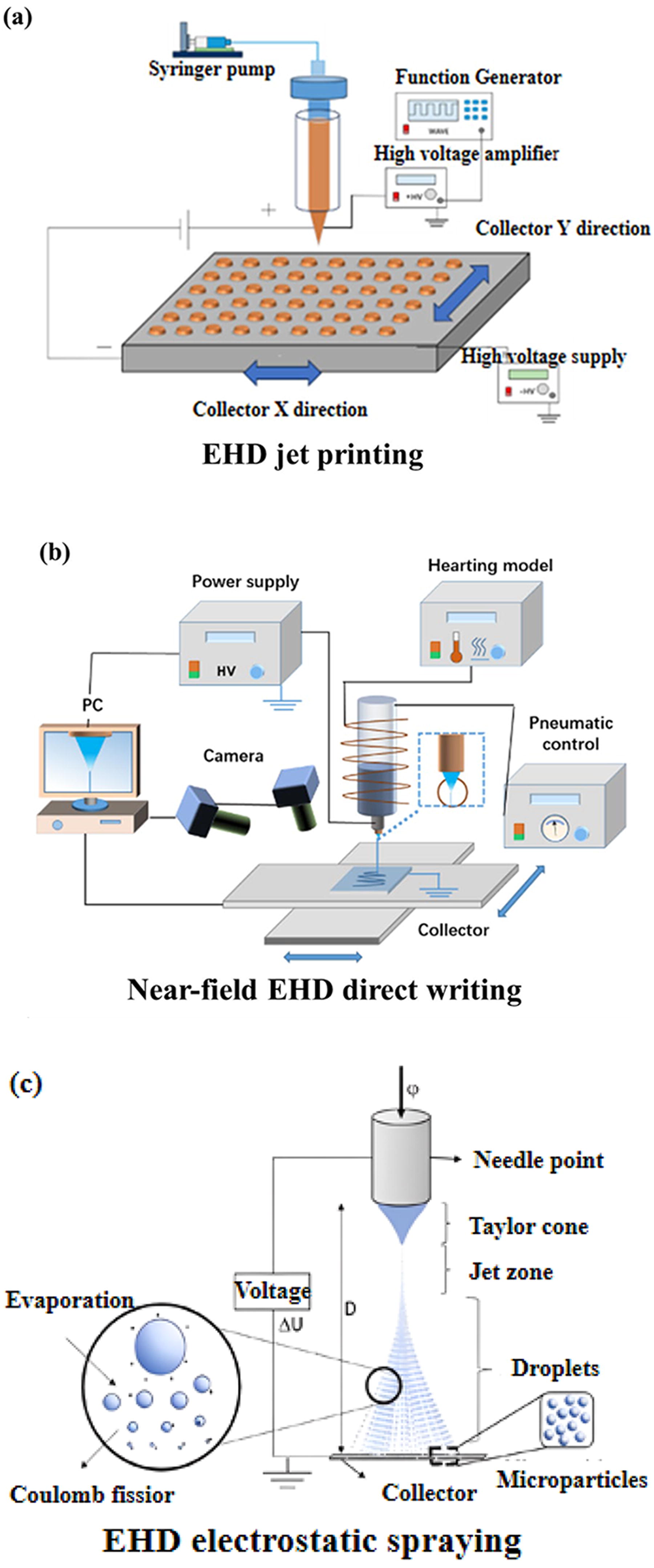
EHD jet printing leverages the electric force to draw the ink downward, which has the advantages of simplifying the printing process and effectively overcoming the capillary force, 23 whose working principle is illustrated in Figure 2(a). During printing, the moving ions are rapidly compelled to the tip of the nozzle with the help of the electric field generated by an appropriate voltage, initiating the formation of the Taylor cone. 25 Subsequently, the electrostatic force induced by the adjustable voltage between the nozzle and the substrate overcomes the surface tension at the tip of the Taylor cone to make the nano-micro ink jets printed onto the substrate from the tip of the nozzle.26,27
Owing to the smaller tip size of the Taylor cone compared with that of the nozzle, EHD jet printing can achieve a high deposition resolution. Comparatively, near-field EHD direct writing originates from electrospinning, 28 which has a similar working principle of EHD jet printing with the difference in printing voltage, as illustrated in Figure 2(b). 24 Specifically, near-field EHD direct writing applies a constant voltage between the nozzle and the substrate for EHD printing. Although the two above EHD printing modes have been widely applied in various fields, they are influenced by various interferences that are coupled with each other.29–31 These interferences to different extents degrade the printing precision of EHD printing, involving imprecise process parameter settings,32,33 improper ink,34,35 unsuitable ambient factors,36,37 nozzle clogging,38,39 imperfect hardware system,40,41 cross talk,42,43 jet lagging,44,45 and imperfect satellite droplets.46,47 Thus, the analysis of these interferences is beneficial to improve the printing precision of EHD printing. To do so, a large number of error correction methods have been designed to suppress the influences of various interferences for EHD printing, which can be roughly divided into parameter-based, hardware-based, and software-based. Specifically, parameter-based correction deals with the settings of process parameters, the material characteristics of the ink, the configurations of the nozzle, the control of the ambient parameters, etc. Hardware-based correction can optimize the hardware structures of the components or the whole system of EHD printing and add some hardware components or additional hardware devices into the EHD printing system. Software-based correction mainly optimizes the process parameters, implements a closed-loop control for the EHD printing hardware system, and compensates for the jet lagging. It is greatly valuable for multierror correction.
In this article, a comprehensive review is provided to analyze the sources of EHD printing errors and existing error correction methods for EHD printing. First, EHD printing errors are divided into several categories according to different error sources, such as process parameters error, ink parameters error, ambient parameters error, nozzle clogging error, hardware system error, cross-talk error, jet lagging error, and satellite droplets error. Then, various correction methods are summarized and discussed for different categories of printing errors. Specially, multierror correction methods are analyzed to discuss the current developments on printing precision improvement for EHD printing when influenced by various interferences coupled with each other. Finally, potential research topics are provided for error correction in EHD printing.
Sources of EHD Printing Errors
To achieve excellent EHD printing, it is essential to delve into the interference factors resulting in print errors. EHD printing errors can be divided into eight types, which will be analyzed in the subsequent subsections. It is noted that six types of printing errors possibly emerge in the two modes of EHD printing, such as process parameters error, ink parameters error, ambient parameters error, nozzle clogging error, cross-talk error, and hardware system error. Another two types of printing errors, such as, jet lagging error and satellite droplets error possibly, emerge in one mode of EHD printing, which are mainly associated with near-field EHD direct writing and with EHD jet printing, respectively.
Process parameters error
Process parameters’ error possibly occurs in both near-field EHD direct writing and EHD jet printing. This error results from inappropriate configurations of some process parameters related to fluid supply, power supply, and nozzle. Compared with EHD jet printing, near-field EHD direct writing is more likely to be interfered by inappropriate process parameters. This is because its printing ink is more susceptible to process parameters, which is molten organic matter and its material state will change after melting. Inappropriate process parameters essentially influence the stability of the state of Taylor cone and extruded jet, especially the jetting volume. The oscillations of the jetting volume can cause fluctuations in jet diameter to further affect the morphology and positioning precision of the printed fibers, which possibly results in some defective jets such as pulsing and long-term beading jets.30,48,49
The process parameters for fluid supply mainly involve feeding air pressure, flow rate, fluid feeding rate and mass flow, which greatly influence the jetting stability. Hochleitner et al. 29 investigated the influence of process parameters for fluid supply on the jet in the near-field EHD direct writing at different feeding air pressures of 0.2, 0.5, 1.0, and 2.0 bars with the parameter configurations of 22 G spinneret, 6.0 kV acceleration voltage, and 4 mm spinning length. They observed that an excessive feed air pressure, particularly over 2.0 bar, could generate long-term beading and pulsing jets. Although a high-quality flow rate can improve production efficiency, exceeding a certain threshold will affect the printed fiber morphology. This threshold varies according to the used printing ink. Haider et al. 50 reported that changes in flow rate resulted in the formation of bead-like jets in variable control experiments. Specifically, when the flow rate was configured as 0.07 mL/min, 0.10 mL/min, and over 0.10 mL/min, the beading demonstrated a strong-to-weak trend with the increase of the flow rate. Mkhize et al. 51 reported that poor jetting would emerge to produce discontinuous printing and the fibers of uneven diameters if the flow rate was reduced to much less than the jetting frequency in EHD jet printing. Zuo et al. 52 observed that when near-field EHD direct writing was performed with a 4 wt% poly(hydroxybutyrate-co-valerate) (PHBV) solution and an applied voltage of 20 kV, bead-like jets with a large diameter would be generated when the fluid feeding rate increased up to 5.6 mL/h. Haigh et al. 53 found that the printing instability occurred at 80°C/0.5 bar, resulting in a pulse phenomenon. After intensive experiments, the instability could be attributed to a low mass flow rate, resulting in an unstable and viscous charged jet.
Power supply is another important factor for stable EHD printing. Hochleitner et al. 29 investigated the impacts of different acceleration voltages on near-field EHD direct writing and found that pulsing and long-term beading occurred at the low voltages of 5.25 kV and 4.5 kV, respectively. Notably, an excessively high voltage causes the formation of long-term beading jets and amplifies the whipping behavior of the polymer jets.52,54 Conversely, an excessively low voltage induces the droplet shape at the nozzle tip to continuously change, leading to unstable jets and long-term beading jets.55,56 Davoodi et al. 33 observed that the force of jet stretching fluctuated when the confrontation height was fixed and the voltage was slightly lower than the optimal voltage, leading to the generation of pulsing jets. Subsequently, further reduction in voltage resulted in the formation of long-term beading, as shown in Figure 3. 33 Huang et al. 57 explored the impact of voltage on the deposition for EHD jet printing under the configurations of a nozzle-to-collector distance of 3.55 mm, a collector speed of 10 mm/s, and a supply rate of 80 µL/h. Their experiments indicated that the jet exhibited instability with a bifurcation of the single jet into two, as the voltage exceeded 4.9 kV.

The installation of a nozzle also influences the printing quality of EHD printing. If the distance between adjacent nozzles is too small, a large electric field interference (EFIF) will occur to make the mutual jets repel each other, resulting in unstable jets. 58 Wunner et al. 32 investigated the influence of the installation of nozzle on the near-field EHD direct writing, which was conducted at different standoff heights with 30 µL/min flow rate and 3.5 kV voltage. They observed that the surface of the printed fibers became rougher and rougher as the standoff height decreased, which greatly degraded the printing precision. Fang et al. 59 studied the influence of the distance between the nozzle and the collector on the jet formation for EHD jet printing. They found that an appropriate distance was beneficial for the formation of the jet, which was within the range of [800, 1200] µm in their EHD jet printing system.
Ink parameters error
After the EHD printing system is well configured, the selected printing ink is significantly important for the printing precision of EHD printing. Unsuitable ink may cause ink parameters error and even printhead wear for both near-field EHD direct writing and EHD jet printing. Specifically, the ink parameters, such as viscosity, conductivity, surface tension, and concentration, contribute to the stability and reliability of the EHD printing system, which deals with mechanical, electrical, physical, and chemical properties of the ink, correspondingly. It is noted that viscosity depends on the molecular weight of the polymer as well as the polymer solution concentration and solvent type. 60
The ink with an excessively high viscosity can cause a rapid solidification of jets to further result in coarse and uneven fibers, seriously affecting the printing precision of EHD printing. 55 Yu et al. 61 observed that the Taylor cone jet area gradually widened as the ink viscosity changed from 9.52 cp to 36.92 cp in the EHD jet printing process. Their experiments indicated that, if the ink viscosity was too high or too low, it would result in poor jet production. Specifically, a low viscosity (<9.52 cp) leads to a narrow Taylor cone jet area to easily form an unstable jet, while a high viscosity (>36.92 cp) prevents the formation of a stable Taylor cone jet. Ahn et al. 62 also observed analogous findings in relation to EHD jet printing, where high ink viscosity led to poor jetting and clumping, while low ink viscosity resulted in numerous line breaks. Nezarati et al. 63 explored the effect of solution viscosity on jet morphology and found that a lower solution viscosity (7.2 ± 1.7 Pa·s) resulted in beading jets under a constant electric field, as shown in Figure 4. They claimed that this was because the lower solution viscosity was not sufficient to resist the defects in jets. Beading formation in electrospun jets occurred when the surface tension in the charged jet was sufficient to reduce the surface area by turning the jet into droplets.
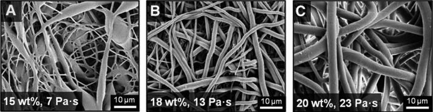
Fiber morphology under different solution viscosities:
Poor ink conductivity can also contribute to jet instability, 64 which adversely affects the morphologies of deposited fibers when the jet becomes discontinuous. 65 As claimed by Topuz et al., 35 an excessive conductivity may destroy the balance between applied voltage and charged droplets, resulting in jet instability and morphology changes of the fibers. These unwelcome changes will reduce the quality of nanofibers to affect their subsequent applications. Moreover, ink conductivity is associated with the long-term beading phenomenon.66,67 Zhang et al. 64 studied the influence of ink conductivity on the jetting in EHD jet printing. They found out that a lower ink electrical conductivity (10−13 Sm−1) led to the inability of the liquid to exhibit cone-jet behavior, resulting in unstable transient jetting.
Ink concentration is closely related to the morphologies of printed fibers. Specifically, a low concentration of printing materials results in a low viscosity, thereby changing the surface tension. If the surface tension exceeds the force of viscosity, it can rupture the spinning jet to result in Rayleigh instability and the formation of beading or nanoparticle structures.55,68–70 Correia et al. 34 conducted an experiment on the effect of polymer concentration on microstructural morphology. They prepared 2% ∼ 10% (w/v) polyvinylidene fluoride (PVDF) solutions and conducted morphological analysis. The results showed that at low concentration [2% (w/v)], no formation of spherical particles was observed; while at medium concentration [5% (w/v)], spherical particles were formed. Finally, at high concentrations [7% and 10% (w/v)], the fibers with nanoparticle structures occurred. Huang et al. 57 investigated the impact of solution concentration on the deposition for EHD jet printing by varying the concentration of poly(ethylene oxide) (PEO) solutions (3%, 8%, 12%, and 15%). Other configurations for their experiments were set as a nozzle-to-collector distance of 3.55 mm, a supply rate of 50 µL/h, a collector speed of 40 mm/s, and a power supply voltage of 3.2 kV. Their experiments demonstrated that the diameter of bead-like structures gradually decreased with the increase of the solution concentration, as shown in Figure 5. Fang et al. 59 used glycerol aqueous solution as the printing material for EHD jet printing with an applied voltage of 2 kV and a nozzle-to-collector distance of 800 µm. They observed that the formation of a stable jet was hindered once the ink concentration exceeded 80%.
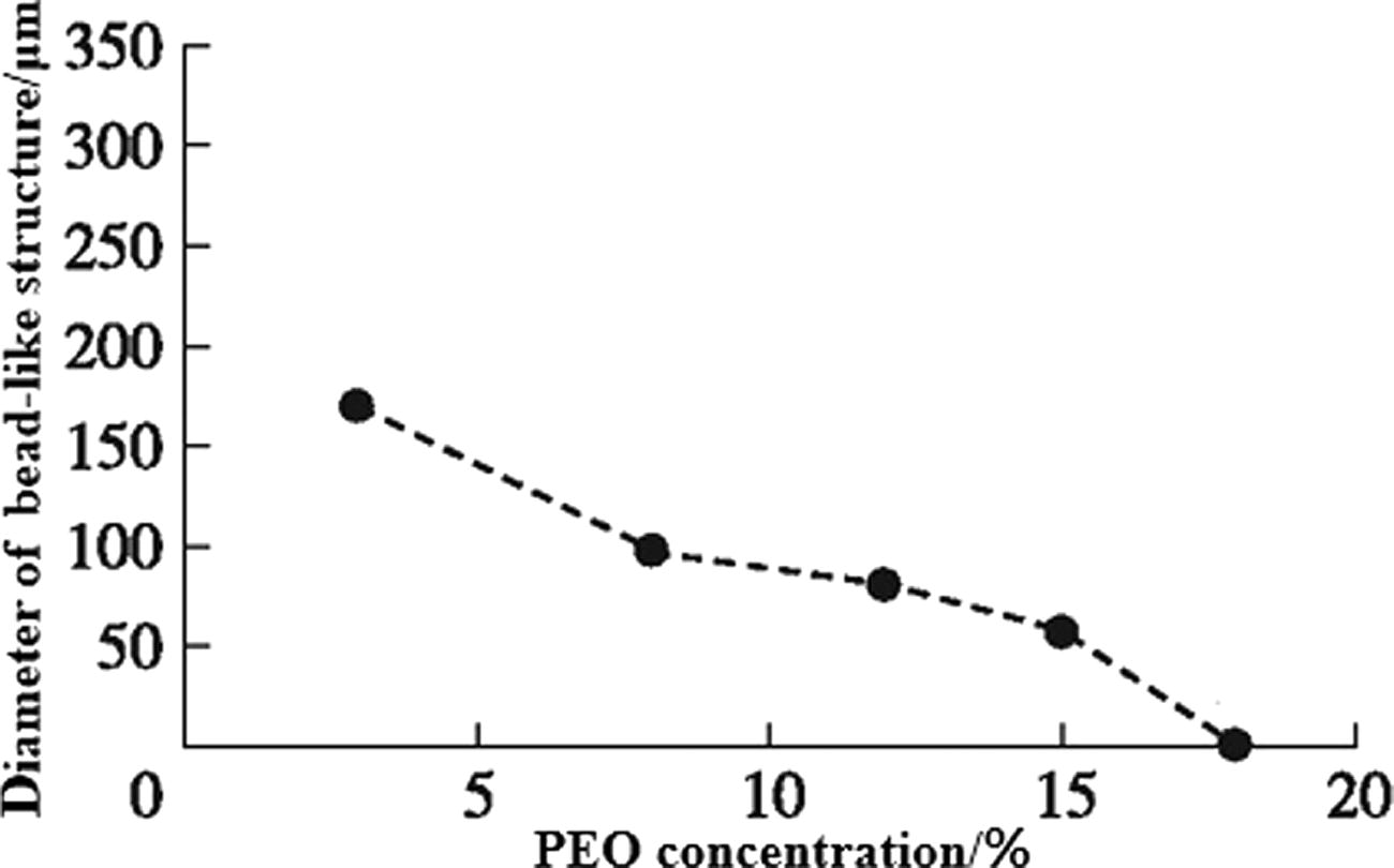
Relationship between PEO concentration and bead-like structure diameter. 57
Surface tension is a crucial parameter for EHD printing inks, which is related to material jetting.71–73 High surface tension solutions may easily lead to printing instability, which can be overcome by a high electrostatic force. 74 Thus, an imbalance between surface tension and electrostatic force can result in higher order printing mode or excessive material being printed.71,72
It is well known that the fluid dynamics of the EHD printing ink is comprehensively influenced by the factors of surface tension and concentration. If its fluid dynamics deviates, the “coffee ring” phenomenon easily emerges, as shown in Figure 6. Specifically, during the drying process, the particles in the ink liquid are migrated to the edge of the droplets, forming a ring-shaped phenomenon known as the coffee ring effect. And it can be summarized that the higher the ink concentration, the more obvious the coffee ring. 75

The particles in the ink are migrated to the edge of the droplets and forming a coffee ring. 75
Ambient parameters error
EHD printing is inevitably interfered by ambient environmental factors, such as temperature, humidity, and vibration, which lead to EHD printing errors. 76 Numerous studies have explored the relationship between ambient environmental factors and jet deposition.
Rodoplu et al. 36 found out that ambient temperature could influence jet deposition morphology. Experiments on near-field EHD direct writing with a 10% wt polyvinyl alcohol solution indicated that the jet deposition appeared bead-like and flat when the ambient temperature fell below 40°C and exceeded 60°C, respectively.
Ambient humidity also has an impact on EHD printing. Park et al. 37 experimentally verified that a high relative humidity (60% RH) could lead to uneven jet deposition morphology in the near-field EHD direct writing when using regenerated filament (concentration 16–19%) at constant temperature (25 ± 1°C). Pelipenko et al. 77 and Ahmadian et al. 78 both experimentally provided similar conclusions. Tripatanasuwan et al. 79 found out that the diameter of PEO fibers at a voltage of 5 kV decreased with the increase of environmental humidity and long-term beading fibers were formed when the environmental humidity increased to 52.6%, as shown in Figure 7. De et al. 80 studied the effect of humidity on fiber formation for a 7 wt% poly(vinylpyrrolidone) solution as a printing ink. Under the conditions of 10 kV applied voltage and 283 K temperature, a high relative humidity (higher than 60%) caused to form unwell-defined fibers.
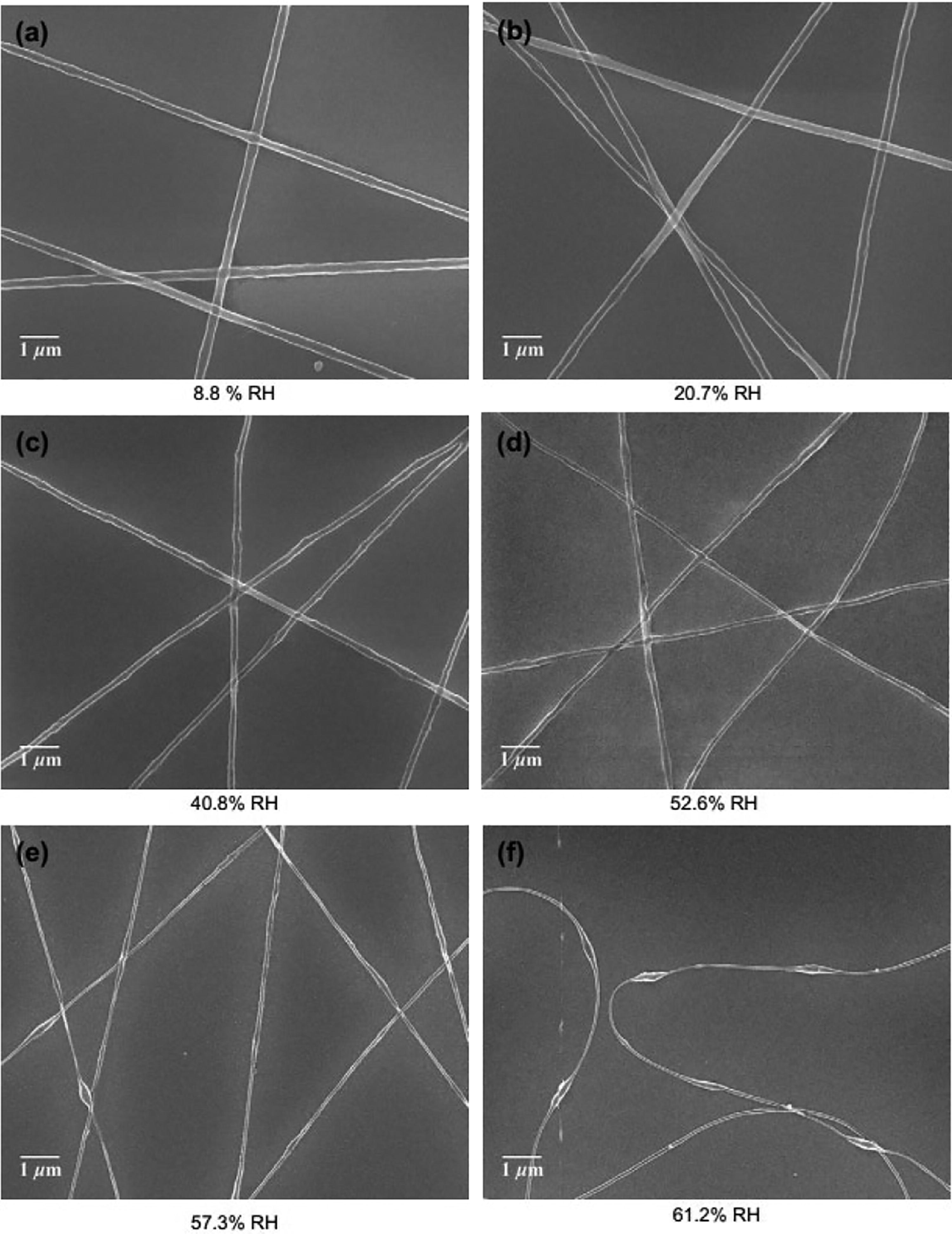
Electron micrographs of polyethylene oxide (PEO) nanofibers from aqueous solution under
In addition, ambient vibrations inevitably influence the height from the collector to the nozzle to further make the magnitude of electrostatic force change. The change of the electrostatic force will influence the jet diameter. Subsequently, the variation of the jet diameter possibly results in deposition errors that significantly reduce printing uniformity and precision. 30
Nozzle clogging error
High precision of EHD printing is ensured based on one of assumption that the printing materials is resistant to nozzle clogging, as depicted in Figure 8. 81 When printing using high-viscosity printing materials or the nozzle with a small diameter, the nozzle easily approaches clogging. 82 Once a large amount of nozzle clogging occurs, the nozzle clogging error emerges, which results in a blank printing space. 83
It can be obsever in SEM that because the large particle size caused by poor solubility in the ink, it makes the nozzle clogging. 81
An excessively high viscosity of the printing materials is resulted from solvent evaporation or ink polymerization.38,39,84 Solvent evaporation rate is an important parameter that determines the viscoelasticity of the jet during EHD printing. Specifically, if the solvent evaporation rate is excessively high or low, nozzle clogging or insufficient drying of the jet easily emerges, respectively. 85 Ink polymerization caused by a high solution concentration increases the ink viscosity, 86 which possibly occurs between micron-sized primary particles for functional inks (such as colloidal suspensions) during EHD jet printing, leading to agglomeration for nozzle clogging. 38
In the realm of EHD printing, careful selection of nozzles is crucial to control nozzle clogging error. Improper nozzle selection, particularly for multinozzle printing, can introduce a critical concern related to electric field mutual exclusion, making the system prone to the risk of multinozzle clogging.87,88 Thus, the nozzle with a proper inner diameter plays an important role in EHD printing precision. The larger the nozzle diameter is, the more likelihood of solution solidification is, thereby heightening the risk of nozzle clogging. 89 Although the nozzle with a small inner diameter can enhance the printing precision, it has the risk that the ink cannot be jetted through the nozzle. 90
Hardware system error
The hardware system for both EHD printing modes typically consists of a high-precision three-axis motion platform, a fluid supply subsystem, and a high-voltage power supply. Owing to imperfect manufacturing of these components, the offsets of printing positions emerge during EHD printing, which can be considered as hardware system error. In addition, the substrate conditions belong to a part of printing hardware, which should be carefully considered to avoid the errors generated from the substrate.
Since the collector mounted on the component is driven by linear electric motors to move on the x-axis and y-axis of the platform, the deviations between the real and ideal deposition positions of ink droplets are accumulated because of imperfect manufacturing and imprecise installation of the component. 40 Although the standoff height can be controlled by the z-axis of the platform, the distance between the nozzle and the collector is deviated from the designed one because of imperfect manufacturing and imprecise installation of the collector and the nozzle. This imprecise distance will result in the deviation of electrostatic field from the ideal one to generate the fluctuations in jetting frequency and droplet diameter. 41 Owing to its imperfect manufacturing and imprecise installation, the EHD printing system may be subject to external disturbances such as mechanical vibration (especially, it operates at a high speed), which can also lead to printing errors. 91
Although only a few literatures specifically have studied the influence of the fluid supply subsystem on EHD printing, inaccurate pneumatic pressure influences the fluid feeding rate to ultimately negatively affect the shape of the Taylor cone. 92 This inaccurate pneumatic pressure is mainly attributed to the instability of the airflow pressure regulating valve or the air source.
As a key component in the EHD printing system, the voltage stability and response speed of the high-voltage power supply directly affect the electrostatic field to further degrade the printing precision. However, because of the nature of hardware circuits, a time delay necessarily occurs for the current voltage reaching the target value. 41 Therefore, it is challenging to ensure a stable applied voltage.
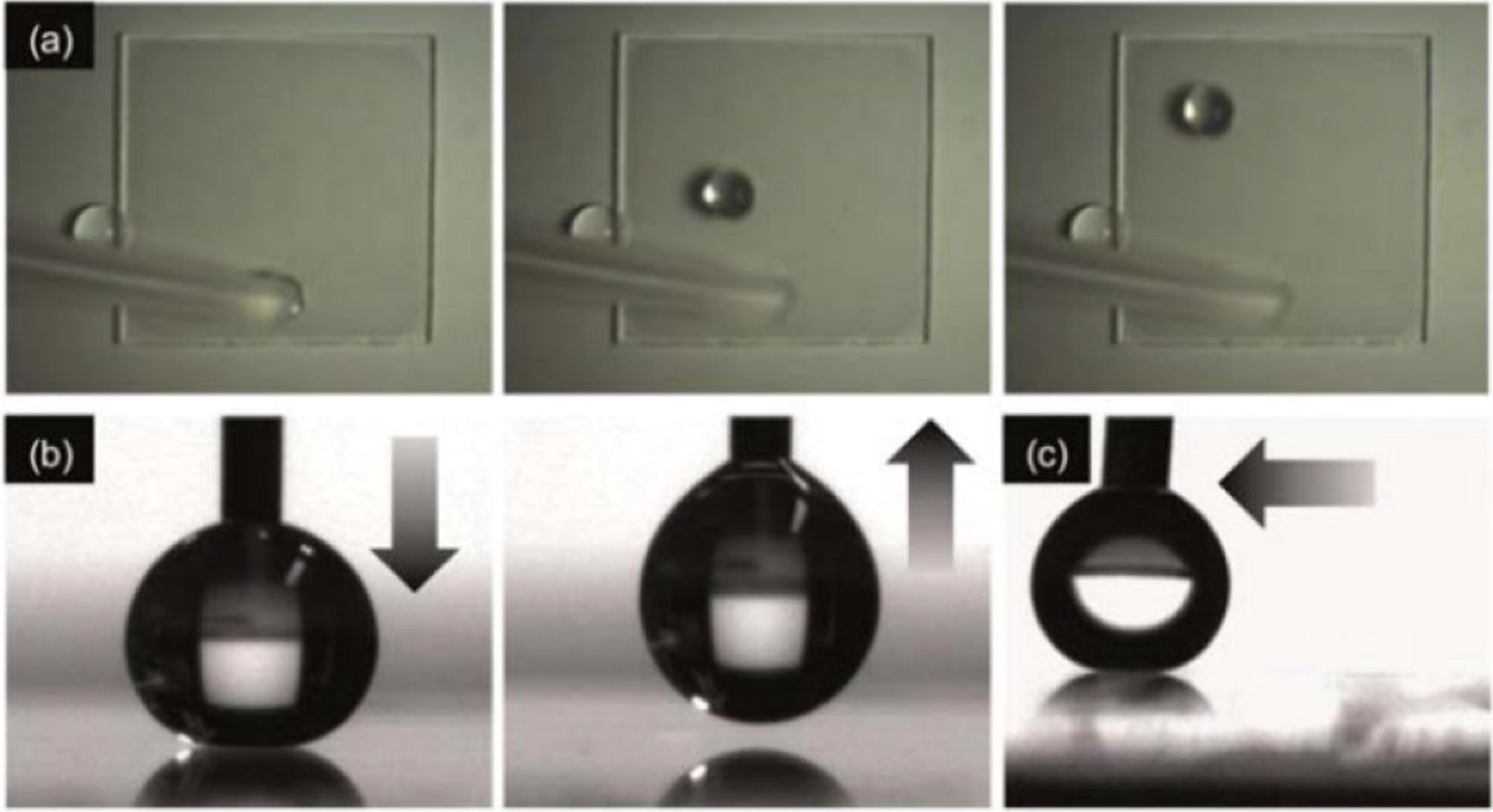
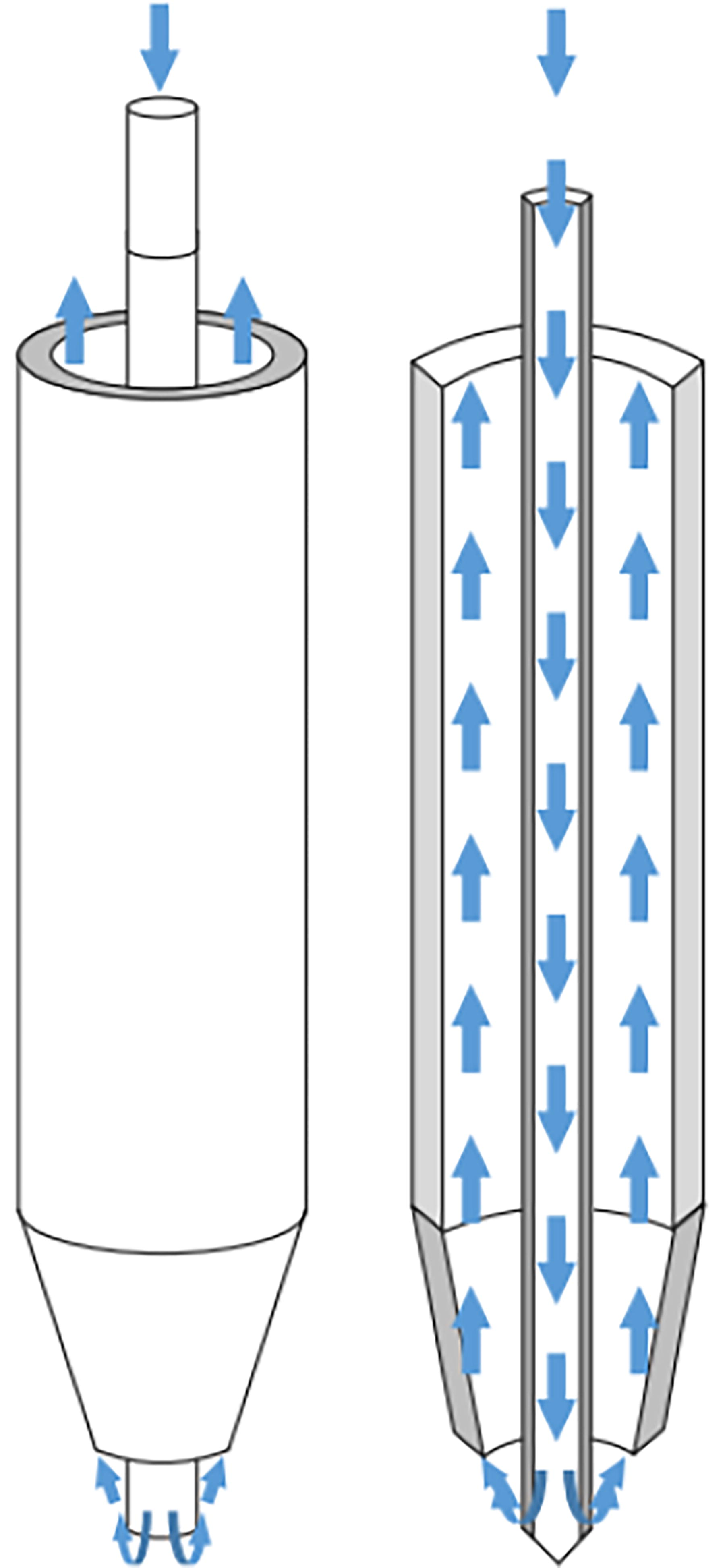
ITO glass exhibits excellent hydrophobicity.
The substrate is generally installed on the collector to receive the jet deposited by near-field EHD direct writing or EHD jet printing. The substrate for EHD printing is the glass attached and coated by an ITO film (also called ITO glass), which has excellent hydrophobicity properties (with high water contact angle 172.1°), as shown in Figure 9 and conductive properties (with the sheet resistances vary from 250 Ω/sq to 170 kΩ/sq).93,94 In order to ensure the performance of ITO glass and the precision of the jet deposition, the substrate should be pretreated before printing to remove the surface dust and to keep it clean. The pretreated method of ITO glass involves immersing it in a solution of acetone is opropyl alcohol for ultrasonic cleaning or rinsing it in deionized water, followed by drying with air flow.59,94
Cross-talk error
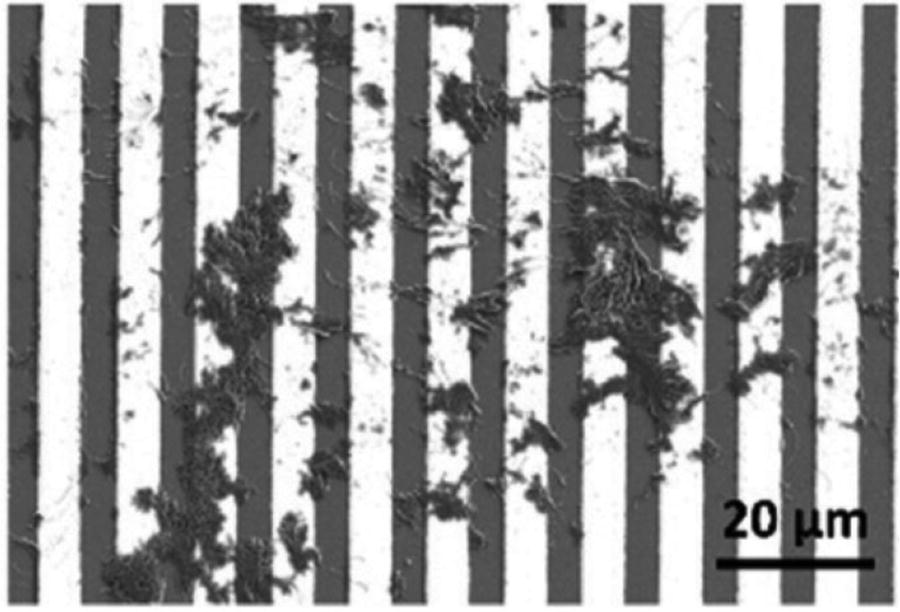
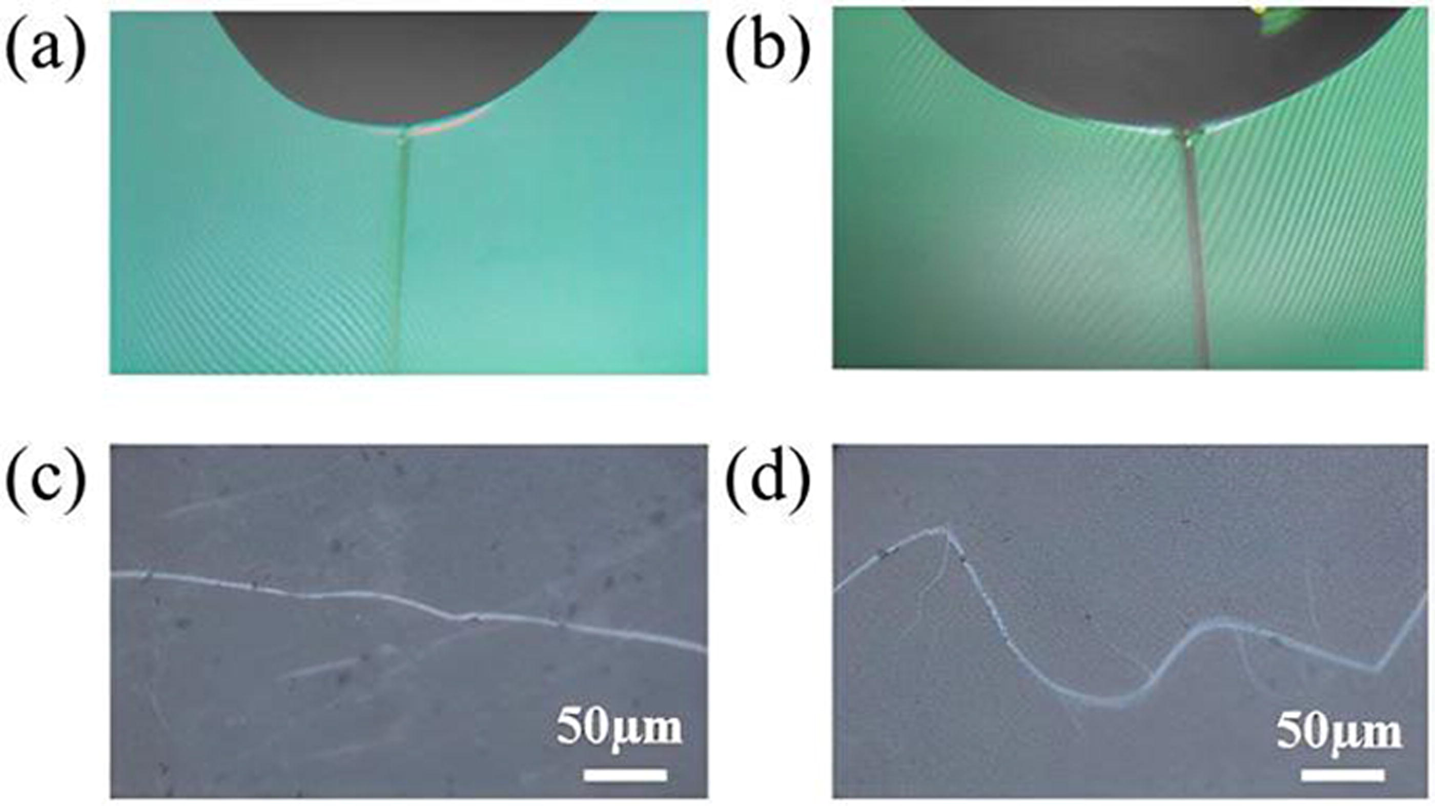
The current printing speed of single-nozzle printing cannot meet the needs of high-efficiency manufacturing, which significantly hinders its application in mass production. 95 The use of multiple nozzles for large-scale electromechanical manufacturing holds an immense potential, but it also poses significant challenges. The unevenly distributed electric field around the Taylor cone of each nozzle weakens the generated liquid jet, resulting in a cross-talk effect.96,97 The cross-talk effect refers to the meniscus deflection under the linear array boundary nozzles because of the asymmetrical electric field caused by the repulsive force between adjacent jets.98–101 Zhang et al. 42 experimentally confirmed that the cross-talk effect between nozzles could lead to uneven deposition spacings to reduce the printing precision of near-field EHD direct writing, as depicted in Figure 10. Thus, it is crucial to control the cross-talk effect of adjacent nozzles in order to achieve precise control of multi-nozzle printing deposition. 102

cInappropriate pitches between adjacent nozzles are one reason of cross-talk effect. 98 Choi et al. 103 studied the influence of the pitches between nozzles on the cross-talk effect in a linear array of three nozzle devices. Their comparative experiments indicated that the asymmetrical electric field for the 3 mm nozzle pitch was stronger than that for the 5 mm nozzle pitch when EHD printing was performed at the flow rate of 0.0025 mL/min and the same applied voltage of less than 5 kV. Furthermore, the asymmetrical enhancement of the electric field aggravated the cross-talk effect.
The material composition of the nozzles is another issue for cross-talk effect. When metal nozzles are used, the metal surface of each nozzle intensifies the repulsive force between its Taylor cone meniscus at its tip and that of its adjacent nozzle. 102 Thus, this intensified repulsive force makes the jets through the nozzles deviate from expected jetting paths.
The cross-talk effect can affect the precision and repeatability of multinozzle EHD printing. To alleviate the impact of the cross-talk effect on the printing precision, it is important to carefully consider the pitches between nozzles and the material characteristics of nozzles.
Jet lagging error
The printing quality in near-field EHD direct writing is mainly evaluated by the stability of the jet deposition path, as described by Cao et al. 104 During the printing process, there is a significant difference between the real deposition path and the designed path because of poor motion control, which is well known as jet lagging error, 44 as shown in Figure 11. It is noted that jet lagging error only emerges in near-field EHD direct writing since the continuous characteristics of its jet make the real deposition path deviate from the designed one. This issue becomes more severe when the real deposition path follows a nonlinear trajectory rather than a linear one, such as zigzag or serpentine deposition.105,106,165

Jet lagging effect. 44
The relative movement between the collector and the nozzle is more and more large with the increase of the moving speed of the collector, resulting in more and more severe jet lagging error.45,107,108 It is noted that the lagging thresholds are different for different ink materials. 49 Tourlomousis et al. 108 printed poly(ε-caprolactone) (PCL) single-layer fibers using near-field EHD direct writing at 18 different moving speeds of the collector to finally determine the lagging threshold as 83 mm/s.
Satellite droplets error
During the process of EHD jet printing, the thinning of the Taylor cone and the existence of plateau Rayleigh instability make it easy to form satellite droplets, as depicted in Figure 12. 46 It is noted that the satellite droplets effect mainly exists in EHD jet printing rather than near-field EHD direct writing since its applied pulse voltage possibly makes the jetting droplets deviate from ideal morphologies. These satellite droplets pose a significant challenge to EHD jet printing quality, especially when the relative movement between the nozzle and the collector is large.31,109 They are mainly related to nozzle parameters and fluid characteristics.
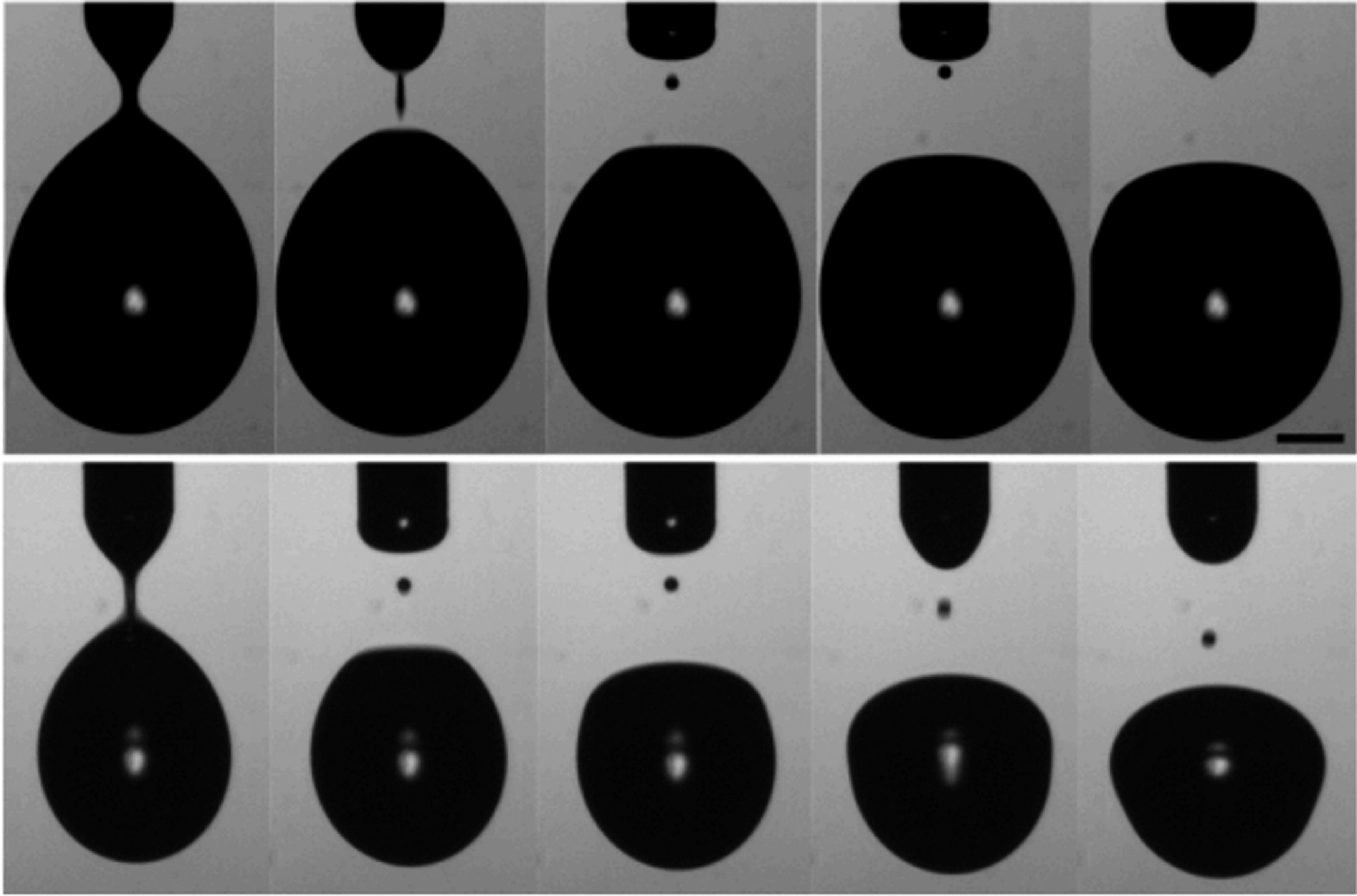
Satellite drop flight behaviors. 46
He et al. 71 found out that nozzle wettability was an important issue for the printing precision of EHD jet printing. They used silicone ink for printing, adjusted the wettability of the inner wall of the nozzle and reasonably configured the parameters (the driving force was 0.0003 µN, the positive and negative force holding times were 5 µs and 3 µs, respectively, and the idle time was 8 µs). Their experiments indicated that hydrophobic nozzles tended to reduce droplet breakup to form droplets with a small volume, thereby increasing the likelihood of satellite droplet formation.
The formation of satellite droplets is mainly influenced by ink viscosity, density, and surface tension.110–112 He et al. 71 conducted an experiment to reveal the relationship between the ink surface tension and the satellite droplet formation, which was conducted under different surface tensions (20 to 85 mN/m) with a relatively stable contact angle (90°) of the inner wall of the nozzle. They found out that inks with low surface tensions were more likely to form satellite droplets. Gong et al. 113 studied the impact of different Ohnesorge (Oh) numbers obtained by adjusting the viscosity on satellite droplets when the electric bond number was maintained at 4.16, and the surface tension was maintained at 0.064N/m. They concluded that the diameter of satellite droplet decreased with the increase of Oh number. In addition, if the charge relaxation time (CRT) of the liquid is too short, this can also lead to the formation of satellite droplets.46,114
Summary of error sources
As mentioned earlier, the printing precision of EHD printing is mainly influenced by eight types of errors. Except jet lagging error in near-field EHD direct writing and satellite droplets error in EHD jet printing, most of errors possibly occur in both EHD printing modes. Even for each type of error, the printing error is induced by different interference factors. For clear demonstration, Table 1 summarizes the eight printing errors for EHD printing with respect to error sources.
Sources of EHD Printing Errors
EHD, electrohydrodynamic.
Error Correction
The printing precision of EHD printing is significantly affected by eight types of errors mentioned above. To improve the printing precision, numerous literatures have designed a large number of error correction strategies to suppress these printing errors. These strategies can be implemented by parameter adjustment, hardware-based and software-based solutions, which will be analyzed later.
Correction of process parameters error
Improper process parameters influence the jetting stability for EHD printing. Many researchers have attempted to suppress the process parameter errors mainly by software-based compensation and parameter adjustment.
Software-based methods are to enhance the effectiveness and the precision of jet deposition. Barton et al. 76 introduced a novel feedback and feedforward method with two degrees of freedom into EHD jet printing, which used an iterative learning control (ILC) algorithm to compensate for repeatable changes of operational conditions. Specifically, the feedback controller adjusted the voltage in real time to mitigate uncertainties during jetting to further enhance the quality of jet deposition, as shown in Figure 13. However, their method only visually and partially captures the jetting performance under several static process parameters to adjust the spinning voltage. This visual and partial strategy cannot adapt to complex operating environments for real EHD printing. Moreover, only adjusting the spinning voltage is limited for the improvement of the printing precision, since the printing precision is determined by several essential process parameters. Nguyen et al. 115 used an image processing method to provide information about the meniscus characterization of Taylor cone. Their method maintained the Taylor cone characterization and ensured the generation of stable jets for high-precision EHD printing, which was implemented by adjusting the spinning voltage when the flow rate of the jet deviated from the expected performance. As they claimed, their method was not suitable for compensating for the high-speed EHD printing with the low-viscosity ink. Zhang et al. 116 applied a model predictive control algorithm to regulate the jet diameter with the spinning voltage, which effectively suppressed jet oscillation. Although adjusting the voltage can to some extent correct some process parameter errors to improve the printing precision, a rapid voltage adjustment will potentially induce instability in the characterization of Taylor cone, which brings the risk of instability to EHD printing. Sun et al. 117 developed a convolutional neural network to classify Taylor cone characterizations into eight categories and predicted the key configurations of process parameters. Although their method can significantly improve the precision of EHD printing because of the adjustment of process parameters in advance, it requires a large amount of training data covering the operating environments as possible, which is not practical for real EHD printing. Ball et al. 118 proposed an offline algorithm to measure the uniformity grade of the jet deposition. They formulated a fitness function for maximizing the uniformity of jet deposition for EHD jet printing by the response surface method and four modern population-based optimization algorithms. However, it only uses several process parameters, such as spinning voltage and the standoff height, to adjust the uniformity of jet deposition, which indicates that it can be further optimized if more process parameters are incorporated. Commonly, the above software-based solutions to process parameter errors require an additional software to possibly consume a large amount of computing resources.

Printing droplet images for constant pressure, feedforward control, and feedforward feedback control. 76 The white line in the image shows the optimized droplet placement.
Parameter adjustment is another correction strategy for process parameters error in EHD printing, which has the direct and effective advantages. Currently, predominant researches focus on effective control of spinning voltage and air feed pressure to ensure the printing precision of EHD printing. Hochleitner et al. 29 adjusted the spinning voltage and the air feed pressure to suppress the generation of pulsing and long-term beading jets. They claimed that voltage adjustment could stabilize the electric field strength to facilitate the high-precision near-field EHD direct writing. Wang et al. 30 adjusted the spinning voltage to mitigate the formation of long-term beading jets. Although parameter adjustment can directly adjust the process parameters to adapt to optimal EHD printing, it requires rich professional experience.
Correction of ink parameters error
The adjustment of ink characteristics provides a feasible strategy to suppress the detrimental effects of low-quality jet deposition, which can reduce the probability of generating pulsating and long-term beading jets. Incorporating excipients into the ink is the widely used method for correcting ink parameter error.
Mkhize et al. 81 and Li et al. 119 have experimentally verified that adding the surfactants and dilute salts could increase the conductivity of the ink and stabilize the jet volume, respectively, which were beneficial for high-precision EHD jet printing. Angammana et al. 66 and Xue et al. 67 proposed increasing the charge density of the ink to produce a uniform electric field distribution, which can suppress the formation of long-term beading jets to further print the high-uniformity and high-precision jets. Yao et al. 120 emphasized the importance of ink concentration in printing high-uniform and high-precision fibers and analyzed the reason the concentration how to affect the state of falling jets. As the solution concentration increased, smoother printing fibers were formed, as shown in Figure 14. Shao et al. 121 also observed the changes of PVDF ink concentrations and viscosity how to influence the mechanical-to-electrical energy conversion of falling jets. Pelipenk et al. 77 found out that high-quality jet deposition could be promoted by adding appropriate excipients, such as surfactants and co-solvents, to reach the suboptimal humidity conditions of the ink.
SEM images of electrospun fiber webs with different PCL concentrations.
120
In summary, correcting the ink characteristics, such as viscosity, conductivity, and concentration, can improve the uniformity and precision of the EHD printing jet to bring high-precision printing. However, adding excipients to ink materials also requires rich professional chemical experience, which is not friendly for ordinary people.
Correction of ambient parameters error
The ambient parameters influence the fluidity, stability, and printing precision of the falling jet during EHD printing, 122 which are mostly controlled by some additional hardware systems.
Soltman et al. 123 additionally added three hardware systems to improve the printing precision of EHD printing in photoelectric display, which could comprehensively weaken the coffee ring effect. Specifically, they deployed heating dehumidification and dehumidifiers to reduce the ambient humidity and cooling systems to control collector temperature for suppressing the wetting bringing induced by ambient environments, as shown in Figure 15.

Cross sectional profiles of uniform lines printed at different temperatures.
123
Improving hardware conditions to correct the ambient parameters error is simple and straightforward. However, additional hardware systems adjusting the ambient parameters, such as dehumidifiers and cooling systems, greatly increase the economic cost.
Correction of nozzle clogging error
Nozzle clogging makes the ink not flow normally in the tube, which subsequently causes the defects and distortion problems in EHD printing. It can be avoided by selecting the appropriate ink and special nozzle structure.
One solution is to ensure the inner diameter of the nozzle is much larger (at least 100 times) than those of the particles in the ink. 86 One is to select the inks with high solubilities and low evaporation rates, 124 which can make the ink flow smoothly in the nozzle to avoid clogging effectively. Modifying ink characteristics is another solution to effectively preventing nozzle clogging. Kwon et al. 125 suggested that introducing wetting agents and surfactants into the ink solvent could reduce the evaporation rate and prevent particle aggregation and agglomeration, which was beneficial for the ink fluid glidingly flowing through the nozzle in EHD jet printing. It is noted that the ink characteristics should adapt to the application requirements in EHD printing, which possibly deal with many factors, such as targeted applications and ambient environments. So, many professional modifications are demanded for ink preparation.
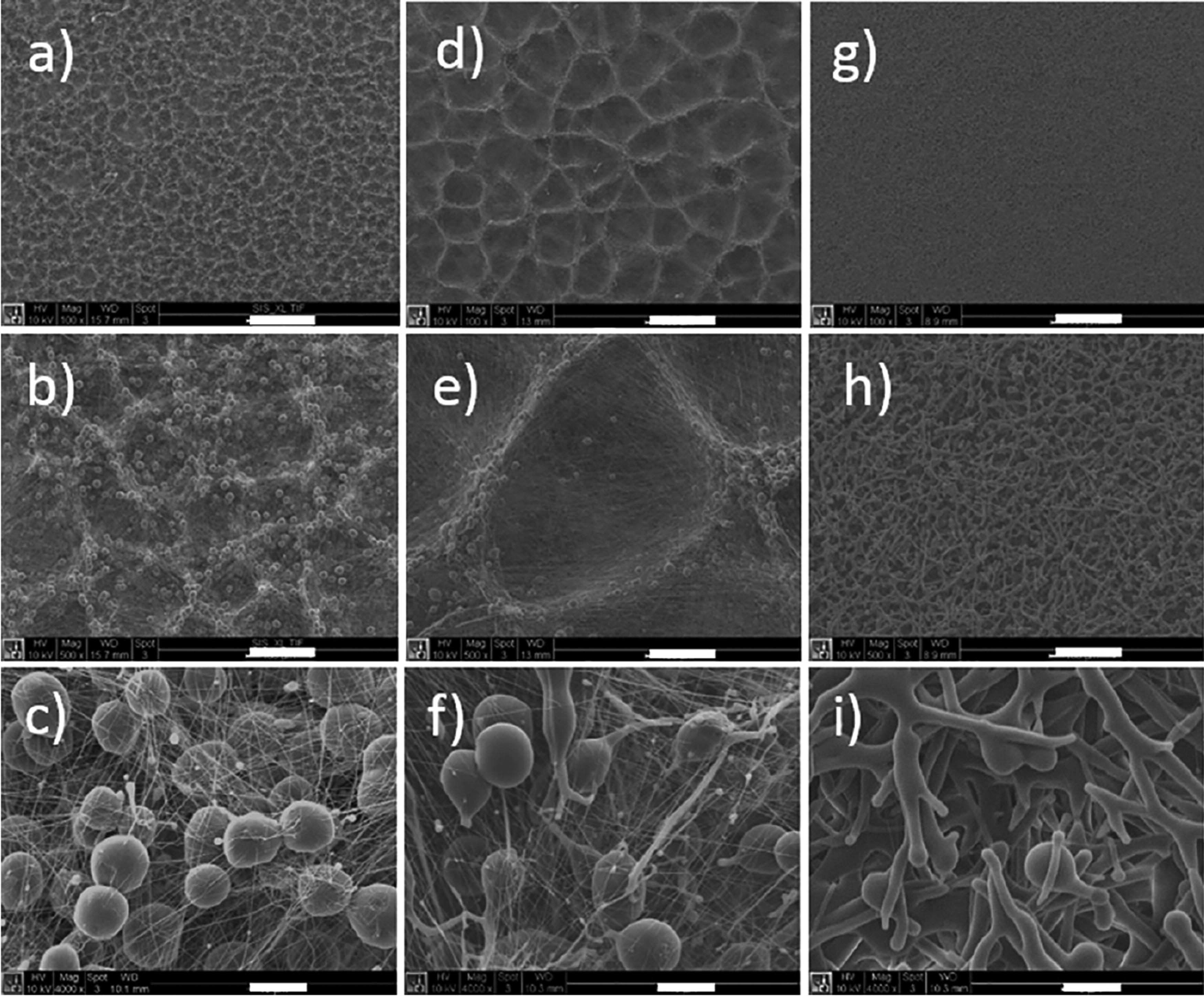
Adjusting the nozzle structure can also suppress nozzle clogging effectively. Li et al. 38 designed a new nozzle with a dual-channel structure to keep the ink flowing between the two channels and to realize the ink circulation path continuously during EHD jet printing, as shown in Figure 16. Their experiments indicated that this nozzle structure could solve the clogging problem for the single-channel nozzle. Yang et al. 126 designed a detachable nozzle, which was made of polydimethylsiloxane (PDMS) material and glass adhered together under pressure and separated. They claimed that it facilitated the nozzle cleaning and kept the ink flowing continuously for avoiding nozzle clogging during EHD printing. Li et al. 39 designed a new coaxial nozzle to automatically adjust the volume of the flow channel, which could minimize nozzle clogging to maintain a stable EHD jet printing process. Recently, a novel EHD printing technology has been rapidly used to eliminate the error of nozzle clogging, which is known as nozzle-free EHD technology. 127 These nozzle-related corrections to some extents suppress nozzle clogging to improve the printing precision of EHD printing. However, they require professional mechanical designs and additional manufacturing costs.
The dual-channel nozzle with the circulating ink path. 38
Correction of hardware system error
Hardware system errors of EHD printing can be suppressed by hardware-based adjustments and software-based methods. Hardware-based adjustments mainly calibrate the three-axis motion system and the fluid supply system. Software-based methods mainly use some algorithms to make the power supply stable.
Sohn et al. 40 provided two hardware-based adjustment solutions for EHD jet printing. One was to use a calibration device such as the laser interferometer to calibrate the three-axis motion system, which could ensure the positioning precision of the collector. The other was to ensure a stable pressure by adding a static pressure control device or a vacuum generation device behind the air compressor, which facilitated the precise allocation of the air pressure for the printing ink to improve printing precision of EHD printing. Gao et al. 128 also provided two hardware-based adjustment strategies for the EHD printing hardware system, which dealt with vibration isolation and voltage control. They placed the three-axis motion platform on a mechanically vibration isolation platform to prevent vibrations from affecting the EHD printing. Also, they designed a nozzle ring electrode to effectively reduce the interference from collector irregularities.
Wang et al. 129 combined the algorithms of current detection and machine vision to achieve real-time monitoring during near-field EHD direct writing. Their experiments indicated that their software-based method could effectively control the shape of ink droplets to improve printing precision. However, the closed-loop control approach used in this method entails a relatively long delay for parameter adjustment, resulting in a discrepancy between the real voltages and the expected ones. Wu et al. 41 proposed a feedforward-feedback iterative control method for near-field EHD direct writing, which compensated for the errors between the expected voltages and the real ones. Experiments indicated that their iterative control could enhance the dynamic response capability of spinning voltage to significantly reduce the voltage delay time, resulting in the improvement of EHD printing precision, as shown in Figure 17. Although their method to some extent decreases the delay effect compared with the method proposed by Gao et al., 128 the iterative control cannot eliminate the voltage response delay.
Jet shape and printing pattern.
41
In summary, the above hardware-based adjustments and software-based methods can to some extent improve the stability of the EHD printing hardware system. However, additional hardware components increase the complexity of the hardware system, which results in additional difficulties in manufacturing, assembly, and maintenance. Furthermore, additional hardware components inevitably bring more economical costs for manufacturing, purchase, and maintenance. Moreover, precise installation and calibration of the three-axis motion system require specialized technical knowledge and experience. Although software-based methods can avoid some problems that existed in hardware-based adjustments, voltage response delay is challenging for them.
Correction of cross-talk error
Cross-talk error only emerges in multinozzle EHD printing to influence the formation and jetting of jets. 130 To suppress the cross-talk effect, plenty of correction methods improve hardware conditions to reduce EFIF. Auxiliary components and the appropriate layout of multiple nozzles are two alternative methods.
Various studies have demonstrated that the auxiliary electrode can adjust the distribution of the electrostatic field to effectively minimize EFIF between nozzles, which can ensure the jets with regular shape and concentrated distribution.131–134 Lee et al. 100 applied conductive materials to the silicon-based surface of the nozzle in EHD jet printing, resulting in the formation of a symmetrical cone-shaped jet pattern that effectively avoided repulsive reactions. Tran et al. 98 used nonconductive nozzles made of polymethylmethacrylate or inserting pseudo-capillary nozzles on both sides of the array to reduce the repulsion at the nozzle tip. Similarly, Si et al. 135 decreased the cross-talk effect by adding an insulated fake nozzle on each side of the five-capillary array.
Zheng et al. 136 designed a novel nozzle module to enhance the uniformity of the electric field for minimizing cross-talk, which could improve the diameter uniformity of the jet, as shown in Figure 18. Liu et al. 137 used plastic sleeve to mitigate EFIF to produce stable and uniform jets after the simulated analysis of the EFIFs under different spinning voltages, nozzle lengths, and nozzle distances. Zhang et al. 42 designed nozzle layout with an appropriate nozzle pitch to minimize the cross-talk effect in near-field EHD direct writing. Choi et al. 138 developed a nozzle array with a triangular structure for cross-talk error correction. Their experiments indicated that the designed nozzle array with different nozzle pitches could to different extents reduce the cross-talk effect, up to 30% (3 mm nozzle pitch) and 60% (5 mm nozzle pitch), respectively. Lee et al. 139 designed an FR-4 multinozzle for EHD jet printing, in which the electric potential was parallel to the nozzle for achieving an interference-free symmetrical cone printing mode. Duan et al. 140 designed a nozzle array chip for EHD jet printing, which consisted of a silicon plate and a polymer SU8 nozzle structure to address the problems of discharging, liquid flooding, and cross-talk behavior. Peng et al. 95 designed a special linear nozzle with dual auxiliary electrodes for EHD jet printing, which significantly suppressed the cross-talk effect. Although gilding the polymer nozzles can improve the conductivity of EHD printing, this gilding process simultaneously intensifies the repulsive effect between the nozzle tips.98,141
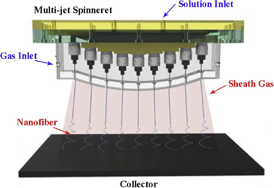
Experimental system of the multi-jet electrospinning with sheath gas. 136
The above studies only focus on the influences of nozzles themselves on the cross-talk to design some specific nozzle arrays and some auxiliary components. Excessively intricate nozzle systems bring challenges for their applications in diverse production scenarios. 95 In addition, these studies seldom pay attention to basic printing specifications including printing precision and uniformity. 43
Correction of jet lagging error
Jet lagging error is attributed to the lack of synchronization between the collector and the nozzle, which directly affects the deposition precision in near-field EHD direct writing. The corrections of jet lagging error mainly include adjusting parameters and software-based methods, among which software-based methods are commonly applied.
Wunner et al. 142 elaborately controlled the air pressure and the moving speed of the collector to correct the jet lagging error. However, it is difficult for the determination of a speed threshold to match the nozzle and the end of the lagging jet.
Fan et al. 143 used Newton interpolation to attain the equivalent diameter formula according to the diameter of the lagging jet for jet lagging error compensation. Cui et al. 144 reconstructed a numerical control program to calculate the optimal speed threshold for jet lagging error correction, which was based on the predicted jet lagging error during virtual machining before it was fed to the real machining. Jin et al. 44 proposed an adaptive control method for the nozzle speed to predict the jet lagging error in advance according to the designed path and real rate, which could facilitate the reconstruction of the path for jet lagging error correction, as shown in Figure 19. It is noted that this approach requires a comprehensive consideration of the interplay between collector speed and other parameters. Hrynevich et al. 146 proposed a computational model based on the collector speed and the designed trajectory to predict the speed threshold, which could achieve the potential printing results and defects in advance. Jin et al. 145 established a relationship between the collector speed and the lagging distance from the perspective of designed path, which compelled the lagging distance to zero with the help of a known collector speed. Liashenko et al. 147 analyzed the deflection of the lagging jet in printed patterns to determine the in situ jetting speed, which could be used to online adjust the falling jet to suppress the jet lagging error.
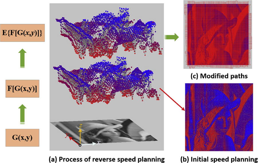
Implementation of initial speed planning on Lena image.
145
Software-based correction can make the adjustment in advance through prejudgment to correct the jet lagging error. However, it requires relatively complicated computations and implementation. Moreover, it can easily lead to incorrect selection of key parameters and ignore the influences of individual parameters because of its weakness in mathematical interpretation. 104 Without understanding the physical processes of jet formation, it is difficult to guarantee high-precision near-field EHD direct writing. 148
Correction of satellite droplets error
Several predominate correction schemes have been provided to correct the satellite droplets error in EHD jet printing, involving the adjustment of the ink characteristics,149–151 the adjustment of process parameters,152,153 and hardware-based methods.47,154–156
Adjusting ink characteristics, especially ink viscosity, is effective to suppress the generation of satellite droplets. Hoath et al. 149 claimed that the ink viscosity played a primary role in the formation of satellite droplets because the shear-thinning fluid related to viscosity directly decided the formation of satellite droplets. Owing to its strong shear-thinning characteristics, the viscosity of the poly (PEDOT: PSS) solution is low within the nozzle and quickly (<100 µs) recovered to be high at the low shear rates once the jet was formed. The influence of shear-thinning characteristics on the ink viscosity was beneficial to suppress satellite droplets, especially when a 0.8 mm standoff height was configured. Morrison et al. 150 established the Lagrangian finite element model to simulate the jetting of non-Newtonian fluids and experimentally verified that the low ink viscosity could suppress the formation of satellite droplets. Sen et al. 151 adjusted the ink viscosity by adding a polymer to stabilize the main droplets and to prevent the formation of satellite droplets. Adjusting the ink viscosity may necessitate additional material handling procedures to potentially introduce other errors, which affect the printing precision and the lifespan of the nozzle.
Some researchers have adjusted process parameters to avoid the generation of satellite droplets. Jiao et al. 152 adjusted the spinning voltage amplitude and jetting frequency to control the formation of satellite droplets. Zhong et al. 153 controlled the height between nozzle and the collector to suppress the satellite droplets error. Their experiments indicated that the formation of satellite droplets could be well controlled when the height was within 20 µm. Appropriate process parameters are different for different EHD printing systems under different ambient environments, which indicates that rich experience in EHD printing process should be required for purposeful adjustments. Moreover, adjusting process parameters for satellite droplets error correction has the risk of introducing other errors.
Some studies introduced the auxiliary hardware components into the EHD printing system to correct satellite droplets error. Kong et al. 155 used additional electrodes to remove highly charged satellite droplets in the electrostatic field. Lee et al. 154 successfully prevented the appearance of satellite droplets by using a ring gate to directly lead the electrostatic force vector toward the substrate. Moreover, they found out that a better satellite droplet suppression effect could be achieved when the hole diameter (represented by R) of the ring gate electrode was 1 mm, as shown in Figure 20. Yang et al. 47 used a superhydrophobic nozzle to enhance the Rayleigh instability of the droplets at the breakpoint, which could make the droplets from the nozzle appear in short ligaments. Dong et al. 156 conducted similar experiments to Young et al. 47 to draw the same conclusions as them. Also, auxiliary hardware components increase the complexity and costs of the EHD printing system.
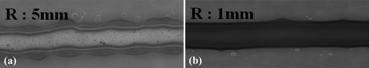
Printing patterns.
154
As mentioned earlier, adjusting ink characteristics and adjusting process parameters can both suppress the bad effect of satellite droplets on printing precision. So, some researchers have combined the two adjustment strategies to comprehensively correct satellite droplets error. Derby et al. 157 successfully mitigated the formation of satellite droplets by modifying the nozzle height and by adjusting the ink viscosity and surface energy. He et al. 71 studied on the relationship between the ink surface tension and the nozzle wettability and found out that the combination of high surface tension inks and hydrophilic nozzle inner walls could effectively prevent the generation of satellite droplets. Multiparameter adjustment increases the complexity of the adjustment.
Correction of multi-error
In real applications, EHD printing is inevitably influenced by various interferences coupled with each other, which indicates that the above correction methods for single types of errors cannot well function. So, multierror correction is promising to suppress the coupled multierror in EHD printing. Owing to high complexity and huge economic cost for the hardware-based strategy, software-based correction strategy is preferable for correction of multiple errors in EHD printing.
Das et al. 158 used a desirability function analysis to achieve optimal process parameter configurations in EHD jet printing. They provided an experimental strategy to jointly optimize process parameters according to the droplet size and the printing frequency. Their experiments explored the relationship between several process parameters (i.e., nozzle height, spinning voltage, and back pressure) and the printing precision. Their team 159 integrated the utility concept with the Taguchi method to tackle the above joint optimization problem, in which different weights were subjectively given to various process parameters. To deal with the shortcomings of subjective determination of weights for various process parameters, their team 160 introduced the principal component analysis to determine the weights for each response variable to enhance the robustness of the weight selection process.
Das et al. 160 have performed several feasible strategies to correct coupled multiple errors in EHD printing. Only using three process parameters to study multierror correction is insufficient for real EHD printing, since its precision is determined by many process parameters and the motion platform as well as ink characteristics as mentioned above.
Summary of error correction
Different corrections can be used for different EHD printing modes to control eight types of errors. Error correction can be implemented by general strategies, which mainly involve parameter adjustment, hardware-based methods, and software-based methods. Parameter adjustment usually deals with the adjustments of ink characteristics (such as viscosity, surface tension, conductivity, concentration, and so on) and of nozzle material (metal or insulating material), of process parameters (such as spinning voltage, nozzle height, collector and so on), and of ambient environment (temperature and humidity). Hardware-based methods usually require the modification of the EHD printing hardware system (such as three-axis motion subsystem, fluid supply subsystem, and applied voltage subsystem). Software-based methods usually use a specific algorithm to predict the printing effect based on relevant parameters in advance to correct EHD printing errors. Table 2 summarizes predominate correction methods for EHD printing according to eight types of error sources. It is noted that multierror correction is also incorporated in Table 2.
EHD Printing Error Correction
CNN, convolutional neural network; DFA, desirability function analysis; EHD, electrohydrodynamic; MPC, model predictive control; PCA, principal component analysis.
Discussion
EHD printing has been widely used to print micro-nano patterns for various applications. 161 In real applications, its printing precision is inevitably degraded by various interferences, which result in corresponding printing errors. These errors mainly result from imperfect hardware system, inappropriate ink, improper process parameters, and ambient environment.40,162 Thus, the analysis of error sources is essential for the precision improvement of EHD printing.
Error printing errors can be categorized into eight types, which are process parameters error, ink parameters error, ambient parameters error, nozzle clogging error, cross-talk error, hardware system error, jet lagging error, and satellite droplets error. It is noted that the first six types possibly emerge in both of EHD printing modes (i.e., near-field EHD direct writing and EHD jet printing). Jet lagging error only occurs in near-field EHD direct writing, whereas satellite droplets error occurs in EHD jet printing. A large number of correction methods have been provided to specifically correct one type of these errors, which are roughly categorized into process-based, hardware-based, and software-based.
Process-based correction mainly deals with the adjustments of process parameters and the preparation of the ink. A series of key process parameters can directly regulate the falling jets to guarantee printing stability and precision, involving spinning voltage, air pressure, standoff height, and plate collector speed. That is to say, jet lagging error and cross-talk error can be effectively reduced if the falling jets are well regulated by the elaborative adjustments of air pressure and collecting plate speed and by the elaborative adjustment of spinning voltage, respectively. In addition, some printing errors can be suppressed by the elaborative preparation of the ink, which adds some appropriate excipients to adjust the ink characteristics, such as conductivity, viscosity, and surface tension. Specifically, these modified inks are beneficial to weaken the generation of pulsating and long-term beading jets, material property error, nozzle clogging, and the formation of satellite droplets. Generally, process-based correction can intuitively prevent errors according to the state of the falling jet, and it is applicable to most materials in EHD printing. However, it requires professional and rich knowledge of process adjustments, which is not friendly to ordinary people to limit its wide applications.
Hardware-based correction mainly involves the design of nozzles, adding auxiliary hardware instruments, and the improvement of the stabilities of hardware subsystems. The design of nozzles mainly refers to the redesign the channel structure of the nozzle, such as designing double-channel nozzles and inserting fake nozzles. It can significantly suppress nozzle clogging error and cross-talk effect error. Adding auxiliary hardware instruments can be helpful to prevent the generation of some types of errors. For example, additional electrodes and ring gates can effectively reduce nozzle clogging error and cross-talk effect error. Improving the stabilities of hardware subsystems can significantly reduce the errors induced by the imperfect EHD printing hardware system. For example, the pneumatic supply device can be optimized at a high-precision level to ensure the stability of air pressure and some isolating schemes can improve the printing stability of the system under mechanical vibration. Commonly, hardware-based correction has a strong pertinence in accurately suppressing errors induced by specific interference factors. This indicates that a specifically designed hardware-based correct-ion scheme is suitable for some specific errors and limited for other ones.
Software-based correction provides viable solutions for various errors, even for hardware system error, which has the advantages of adaptability and flexibility. For example, the feedforward and feedback method can effectively reduce hardware system errors, and the machine vision-based current detection method can significantly reduce the process parameter error induced by the spinning voltage. Most software-based correction methods rely on specific algorithms to forecast printing outcomes and subsequently determine optimal process parameters. However, it is a challenging task for software-based correction to optimally regulate multiple parameters and responses in EHD printing, which makes high-precision EHD printing complicated. 160
Current error correction methods mostly focus on one type of eight printing errors in EHD printing. In real applications, EHD printing is inevitably influenced by various interferences, which are coupled with each other. For example, jet lagging and cross-talk effect as well as other possible errors simultaneously emerge in the multinozzle near-field direct printing, which cannot be separated from each other because of the coupling. The fact indicates that current single-error correction methods cannot excellently improve the printing precision of EHD printing in real applications. So, the study of the coupling mechanism for various errors is significant for error correction for EHD printing in real applications.
In the future, some research topics can be studied to further improve the printing precision of EHD printing precision, as summarized as follows.
First, the multierror coupling mechanism of EHD printing will be deeply studied to reveal the inherent mechanism of EHD printing precision. To do so, some theoretical models will be established to simulate the EHD printing error induced by coupled interferences. Then, the experiments will be elaboratively designed to verify these theoretical models. Finally, software-based correction is purposely designed according to the theoretical model.
Second, studying the formation of jet trajectory during printing is a promising topic to construct the jet deposition model to predict the real path,163,164 which can directly guarantee the deposition precision for EHD printing. This promising scheme can avoid the complicated study of the coupling error mechanism of EHD printing.
Third, the morphology of the deposited fiber on the collector directly reflects the printing precision of EHD printing. In the future, it will be also necessary to explore the wettability of collector and the coupling force how to act on the morphology of deposited fiber. 73
Finally, signal processing-based compensation will be a hotspot topic for EHD printing in the future, since it directly compensates for the acquired printing signal. For example, it can transform the problem of error correction into extracting the trend of the printing signal, which can be implemented by some signal processing algorithms, such as empirical mode decomposition. Also, deep learning can be used to establish a compensation model for the EHD printing signal because of its self-learning ability and data-driven characteristics.
Footnotes
Authors’ Contributions
N.C.: Supervision (lead); validation (lead); methodology (equal); resources (equal); and funding acquisition (lead). X.C.: Conceptualization (lead); methodology (lead); investigation (lead); writing—original draft (lead); validation (equal); and formal analysis (lead). W.O.: Supervision (lead) and formal analysis (equal). Z.W.: Conceptualization (equal) and investigation (supporting). G.Z.: Validation (equal) and funding acquisition (equal). H.W.: Validation (supporting) and funding acquisition (equal). J.Z.: Conceptualization (supporting) and investigation (equal).
Data Availability
Data sharing is not applicable to this article as no datasets were generated or analyzed during the current study.
Author Disclosure Statement
The authors state no conflict of interest.
Funding Information
This work was supported in part by the