
Abstract
In order to enhance the durability, high temperature corrosion resistance, and strength of SS316L in industrial applications, it is recommended to utilize Inconel 625 as a more efficient and costly covering material. Consequently, a double-wire and double-pulse metal inert gas welding process was employed to fabricate two thin-walled SS316L/Inconel 625 functionally graded materials (FGMs) with gradients of 25% and 5%. Subsequent analysis focused on the morphology, microstructure, and properties of the fabricated materials. The findings indicated that this process is a recommended method for manufacturing gradient materials. A consistent transition gradient of 5% resulted in a more stable deposition process, higher forming efficiency, and improved material properties. Evident fractures were observed along the dendrite growth in 75% SS316L area, specifically at the boundary of cellular dendrites analyzed by energy dispersive spectrometer and electron backscattered diffraction. Furthermore, hardness increased and tensile strength decreased along the build direction, specifically the lowest tensile strength was observed in the 75% SS316L/25% Inconel 625 area. Consequently, when selecting gradients for stainless steel and nickel alloy materials, it is advisable to avoid proximity to the 75% SS316L region when dealing with two dissimilar materials. The manufactured FGMs in this study were superior to the wrought value, then the mechanical properties were higher than SS316L and lower than Inconel 625 manufacturing of single material, and the anisotropy was not obvious, in addition, the cost of FGM is lower than that of single /Inconel 625 material. It can improve the problem that the gradient transition zone is easy to fail, reduce the cost, and extend the service life of the parts while meeting performance requirements. Therefore, this achievement can have a significant impact on enhancing the service life and preventing premature failure of dissimilar structure components.
Introduction
The utilization of stainless steel/nickel-based alloy dissimilar metal joints is increasingly prevalent in various industries due to the demand for economic structures, such as aerospace, transportation, bioengineering, nuclear power, navigation, and military fields.1-3 For example, in oil-reformer towers, Inconel is used in dampers, as the temperature can reach 1000 °C, and the atmosphere is both oxidizing and carburizing whereas the rotating axles controlling the damper motion are exposed to a lower temperature and made of austenitic stainless steels. 1 Moreover, Inconel 625 is utilized with AISI 304/316L for the application of a subscale pool boiler which is operated at a higher temperature in a corrosive environment. 2 However, the rapid changes in chemical composition and properties of the interface between dissimilar materials can lead to structural deformation and high gradient residual stress, making the joint susceptible to failure. Functionally graded materials (FGM), which have gradually changed chemical composition, microstructure, and properties, have been identified as potential solutions to these issues.3,4
The scanning strategy and manufacturing parameters of additive manufacturing (AM) can be easily modified, rendering it suitable for manufacturing functionally gradient materials. FGM produced by AM has been utilized for high-throughput testing in various applications, including assessing radiation damage, 5 studying corrosion behavior in stainless steel, 6 and analyzing the magnetic and mechanical properties of cobalt–iron–nickel alloys. 7
Chandrasekaran et al. 8 conducted a study on the fabrication of offshore riser FGM using Cold Metal Transfer (CMT). The experimental findings indicated an enhancement in the mechanical strength of the FGM interface as a result of the development of a defect-free finely cured microstructure. Subsequent, spectroscopic testing confirmed that the chromium enrichment from duplex stainless steel to carbon manganese steel was confined to a depth of 100 microns. In addition, the corrosion rate of duplex stainless steel exhibited a 12-fold increase. Accordingly, the above researches suggest that arc AM of functionally gradient materials is feasible and can lead to performance improvement.
Numerous studies have investigated the fusion of copper on stainless steel and tool steel, utilizing nickel-based alloys as intermediate transition layers. Consequently, the fusion of nickel-based alloys with stainless steel is essential and forms the basis for the transition in the manufacturing of fusion copper. 9
Nevertheless, certain research findings on AM FGM have indicated that stainless steel and nickel-based alloy gradient materials may exhibit phase transformation structures within specific gradient proportion ranges, leading to diminished performance. 10 The research findings cited in references, 11 and, 12 similarly indicated that the fracture occurred in close proximity to the gradient ratio between 25% Inconel 625 and 0% Inconel 625 in the gradient material samples produced. Kim et al. 13 produced the FGM of Inconel 718/SS316L through direct energy deposition. They found that the presence of intermetallic compounds and carbides in specific components of 30% Inconel 718/70% SS316L and 20% Inconel 718/80% SS316L led to the formation of critical pores and cracks (defects). Furthermore, Yu et al. 14 produced a 10-layer gradient material of SS316L/Inconel 625 with a 25% gradient by plasma welding. They demonstrated the feasibility of this material and manufacturing method but found that the performance of the 75% SS316L region was poor. However, they did not investigate more layers or other gradients.
Moreover, limited research exists on the production of gradient materials through AM using double-wire and double-pulse metal inert gas welding (MIG). Consequently, this study employed the mentioned manufacturing method to manufacture straight wall structures with 5% and 25% gradients and concentrated on investigating the behavior in the area of 67% SS316L and 33% Inconel 625.
Materials and Methods
The AM platform for FGM included a wire feeder, shielding gas, infrared thermal imager, industrial control computer, dual-channel voltage and current data acquisition system, and a high-precision KUKA six-axis robot, as depicted in Figure 1. SS316L austenitic stainless steel and nickel-based superalloy Inconel 625 wires, each with a diameter of 1.2 mm, were utilized to fabricate gradient wall structures. The composition of the two wires is detailed in Table 1. An infrared thermal imager and a data acquisition system were employed to capture the side image of the deposition pool and the electrical signal of twin-wire deposition, respectively.
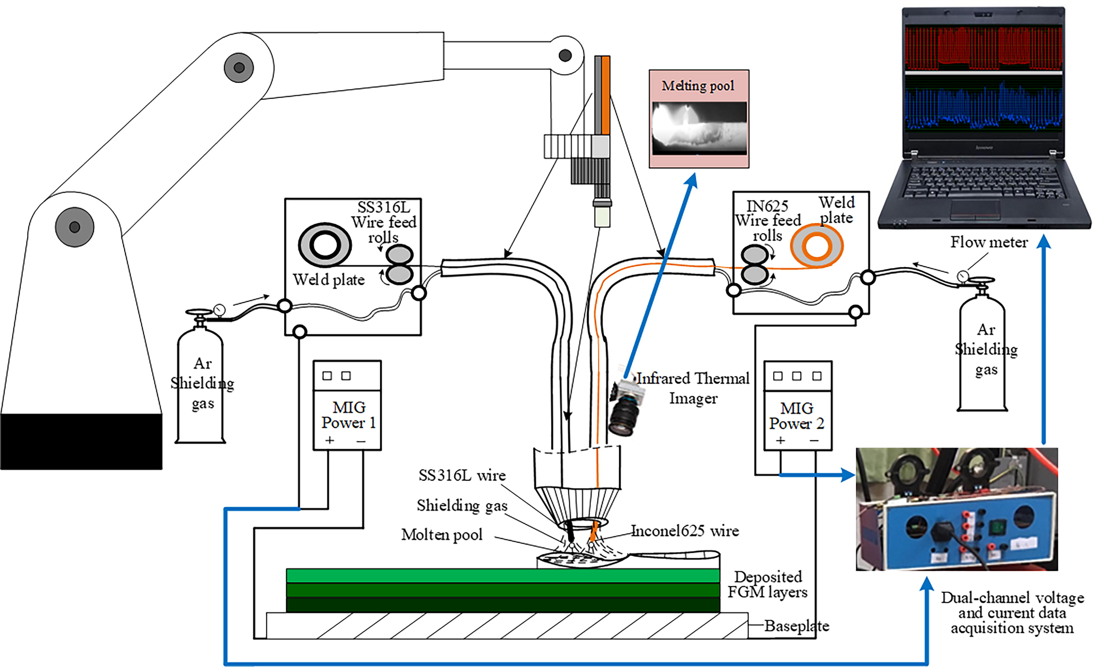
Platform of FGM arc additive manufacturing. FGM, functionally graded materials.
Composition of Two Wires Used in Weight Percent (%)
To examine the influence of gradient compositions on the deposition characteristics, two thin-walled samples FGM1 and FGM2 were produced on an SS316L substrate using an AM platform, which adapts 25% and 5% intervals of gradient transition, respectively, as illustrated in Figure 2. Different gradients of samples were achieved by adjusting the wire feeding speed ratio, with the ratio settings for different layers detailed in Table 2. Twin-pulse MIG welding was used to deposit 50 layers at a 3 Hz low-frequency, with each layer allowed to cool for 30 s. The shielding gas employed was 99.99% highly pure argon, with a gas flow of 24 L/min. The wire extension was 12 mm, and the welding supply adeptly detected and self-adjusted the arc length, preventing arc extinguishing even at high speeds.
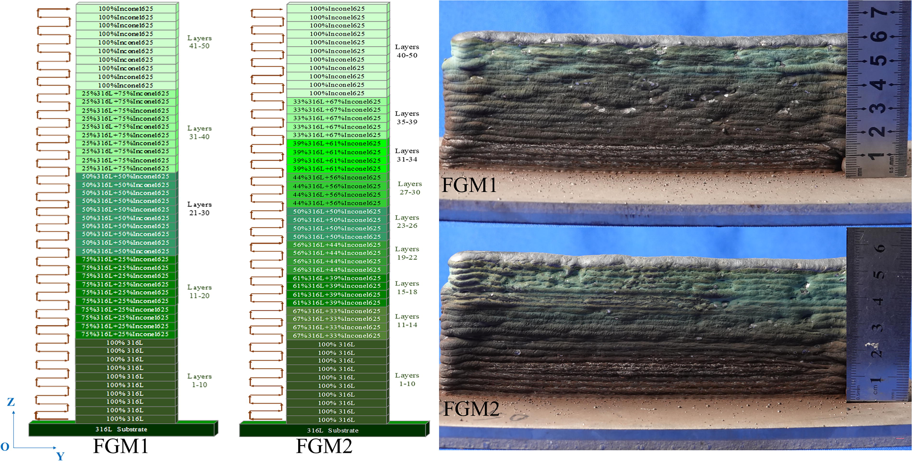
Fabricated samples of FGM1 and FGM2 with different gradient compositions. FGM, functionally graded materials.
FGM Deposition Experiment Parameters
FGM, functionally graded materials.
Following the deposition process, a grinding machine was utilized to grind out the oxide surface. Samples measuring 10 mm in length were cut in both transverse and longitudinal sections to prepare microstructure and hardness samples, as indicated in Figure 1a. The metallographic samples were cleaned with acetone to remove grease and then cold inlaid. Subsequently, sandpapers with grit sizes of 180#, 600#, 800#, 1200#, 2500#, and 5000# were employed for grinding until the surface exhibited no discernible scratches. Then, the samples underwent polishing using a diamond polishing agent with 2.5 μm particles. Finally, samples underwent etching by aqua regia (HCl: HNO3 = 3:1) for a duration of 40 s, followed by rinsing with clear water and alcohol, and then drying. The microstructural characteristics and energy dispersive spectrometer (EDS) analysis of the deposition were conducted using the NOVA NANO scanning electron microscope (SEM) 430. In addition, electron backscattered diffraction (EBSD) was employed to investigate the grain morphology and boundaries of the 75% SS316L graded area, as well as the pure SS316L and Inconel 625 layers. Subsequently, microhardness along the deposited direction was assessed using the HMV-2T micro-Vickers hardness instrument with a 0.5 kg load maintained for 10 s.
Six horizontal samples, labeled as H1 to H6, were obtained from various positions along the gradient ratio, while two vertical samples, labeled as V1 and V2, were extracted from the right section, then the dimensions of the tensile specimen are shown in Figure 3. In addition, two EBSD samples were obtained alongside the microstructural sample. The sampling method is illustrated in Figure 4. Three samples were collected in the X direction at each position to minimize testing errors. In accordance with the GB/T 228-2002 standard, the strain rate for a tensile test at a rate of 2 mm/min at ambient temperature using an electronic universal testing machine CMT5105 with a maximum load capacity of 100 kN. The fracture morphology of fractured samples was observed using a NOVA NANO SEM 430.
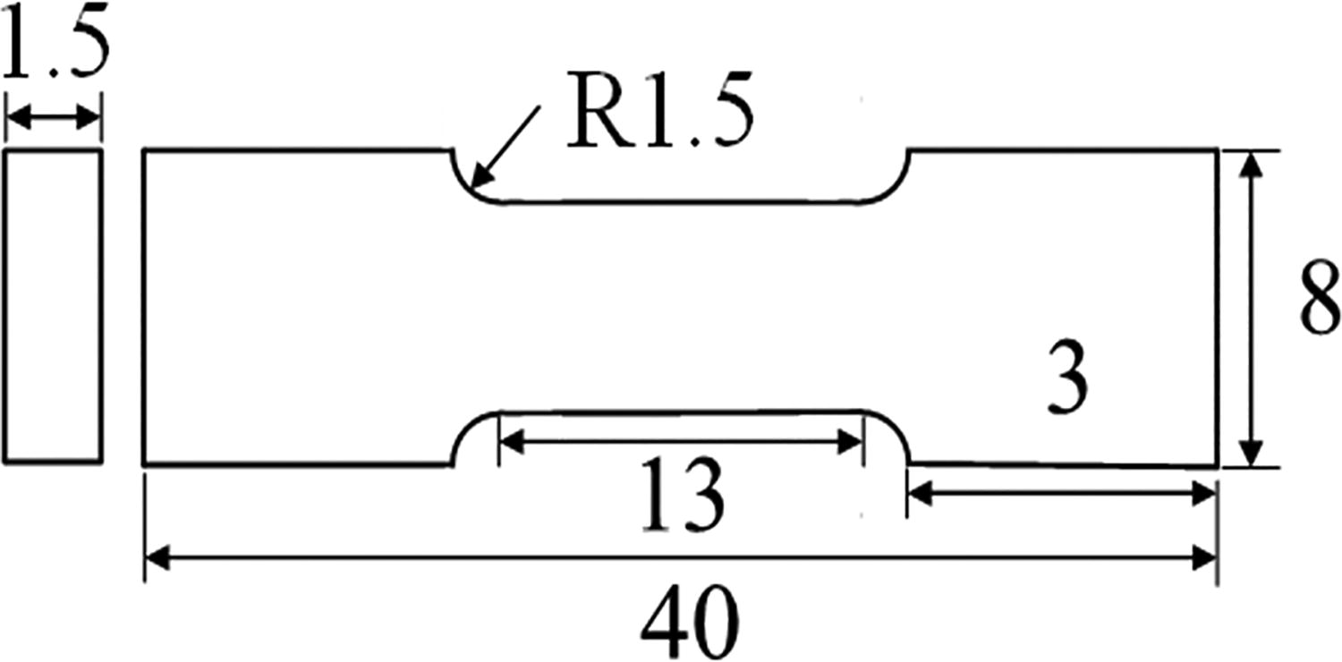
Dimension diagram of a tensile specimen.

Sampling locations of FGM1 and FGM2. FGM, functionally graded materials.
Results and Discussion
As shown in Figure 2, the layers exhibit a gradient coloration of two metals. The difference in starting points at each end stemmed from the varying locations of arc initiation and termination of the double-wire. Nevertheless, this error can be disregarded as both ends were cut off during processing. The disparity in height between FGM1 and FGM2 can be attributed to varying gradient ratios. The gradient difference between the two wires in FGM2 was minimal, while the combination of the two wires resulted in a substantial generation of arc heat. Under identical electrical currents, the heat accumulation in the molten pool exhibited increased intensity, resulting in a wider width and reduced height.
The morphology of the molten pool in different deposition layers of FGM1 is illustrated in Figure 5. As the number of layers increased from 11 to 40 under the influence of a double-arc, the solidification time was prolonged due to heat accumulation, leading to an increase in the size of the molten pool. The uneven composition resulted from the gradual dropping of molten droplets into the molten pool over time, caused by the addition of a small quantity of Inconel 625 welding wire in the 12th layer. In the 24th layer, the double-arc was evenly distributed, resulting in uniformity of the two metal components in the molten pool. In summary, the molten pool and arc exhibit a relatively stable behavior throughout the entire deposition process.

FGM1 deposition image of different layers. FGM, functionally graded materials.
The voltage and current waveforms of the double-wire during the 12th layer deposition of FGM1 in Figure 6 exhibit a distinct double-pulse waveform, with the low-frequency of the twin-pulse measured at 3 Hz. The mean deposition current and voltage for SS316L wire were 159 A and 20.7 V, and 64 A and 17.9 V for Inconel 625 wire, respectively. These values were in line with the set parameters, suggesting a relatively stable deposition process.
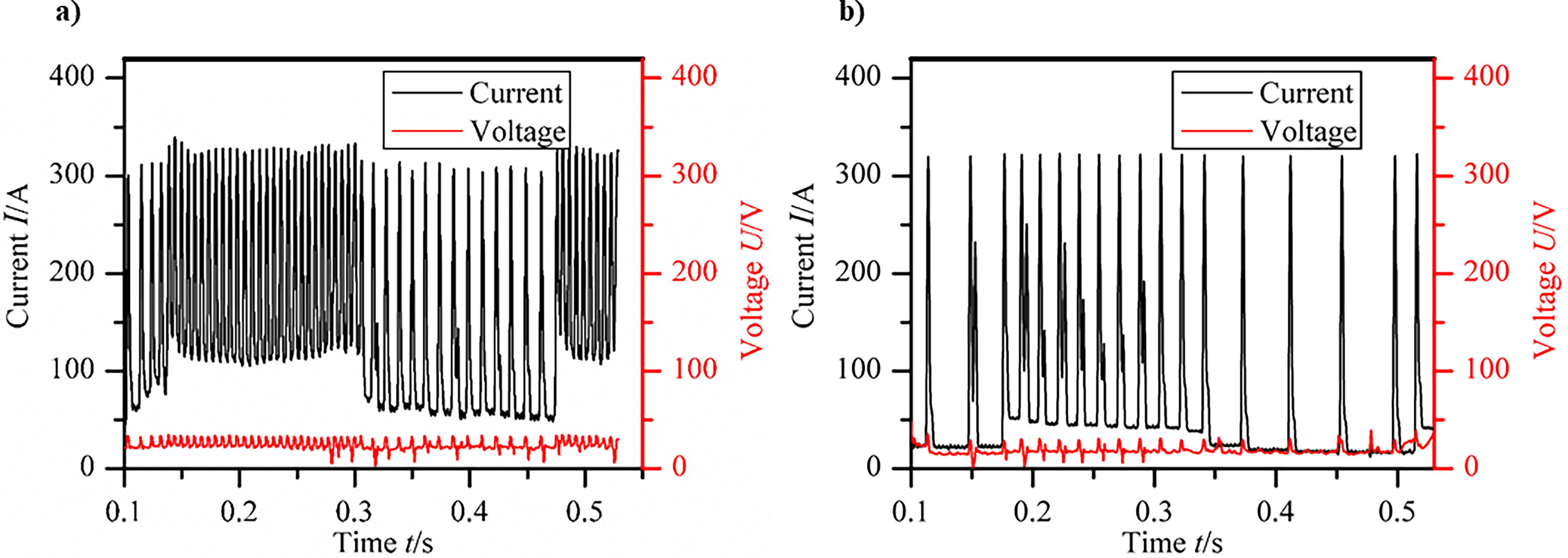
Partial electrical waveforms by 75% SS316L/25% Inconel 625 on the 12th layer of FGM1;
The effective cross-sectional area was determined using the calculation method outlined in references, 15 and, 16 yielding an approximation of the effective deposition rate. The effective deposition areas of FGM1 and FGM2 were 300 mm2 and 370.5 mm2, respectively. Furthermore, the deposition rates were found to be 53% and 65.4%, respectively, indicating their effectiveness. This phenomenon occurs due to the increased proportion of dissimilar materials in the gradient, leading to greater instability in the deposition process. This instability affects the arc and molten pool formed by the two welding wires, resulting in poorer formation. Nevertheless, the uniform transition gradient facilitated a more stable deposition process when transitioning between two wire feeding speeds, leading to relatively improved forming and higher forming efficiency.
According to the equivalent contents of Cr and Ni in the Schaefer diagram, the positioning of gradient regions in FGM1 and FGM2 was established, as shown in Figure 7. The similarity of the gradients of the two samples exhibited a consistent linear growth in the graph. In addition, it was observed that the gradient areas were situated within the single-phase austenite zone.

Schaeffler diagram used for predicting microstructures of graded ratios.
The cross-section is depicted in Figure 8, revealing clearly observable deposited remelted layers with an epitaxial columnar crystal structure. Subsequently, SEM analysis and testing methods were employed to investigate the microstructure in various graded areas of the samples. The microstructure of the 100% SS316L area at the bottom primarily consisted of austenite and ferrite, with no precipitates present. The solidification process of deposited metals results in the formation of δ-ferrite dendrites with high Cr. Subsequently, as the temperature decreases, external dendrites with lower Cr content are formed. As the temperature decreased, the outer section of the dendrite underwent a transformation into austenite, resulting in the formation of a ferrite skeleton with Cr present at the core of the dendrite.
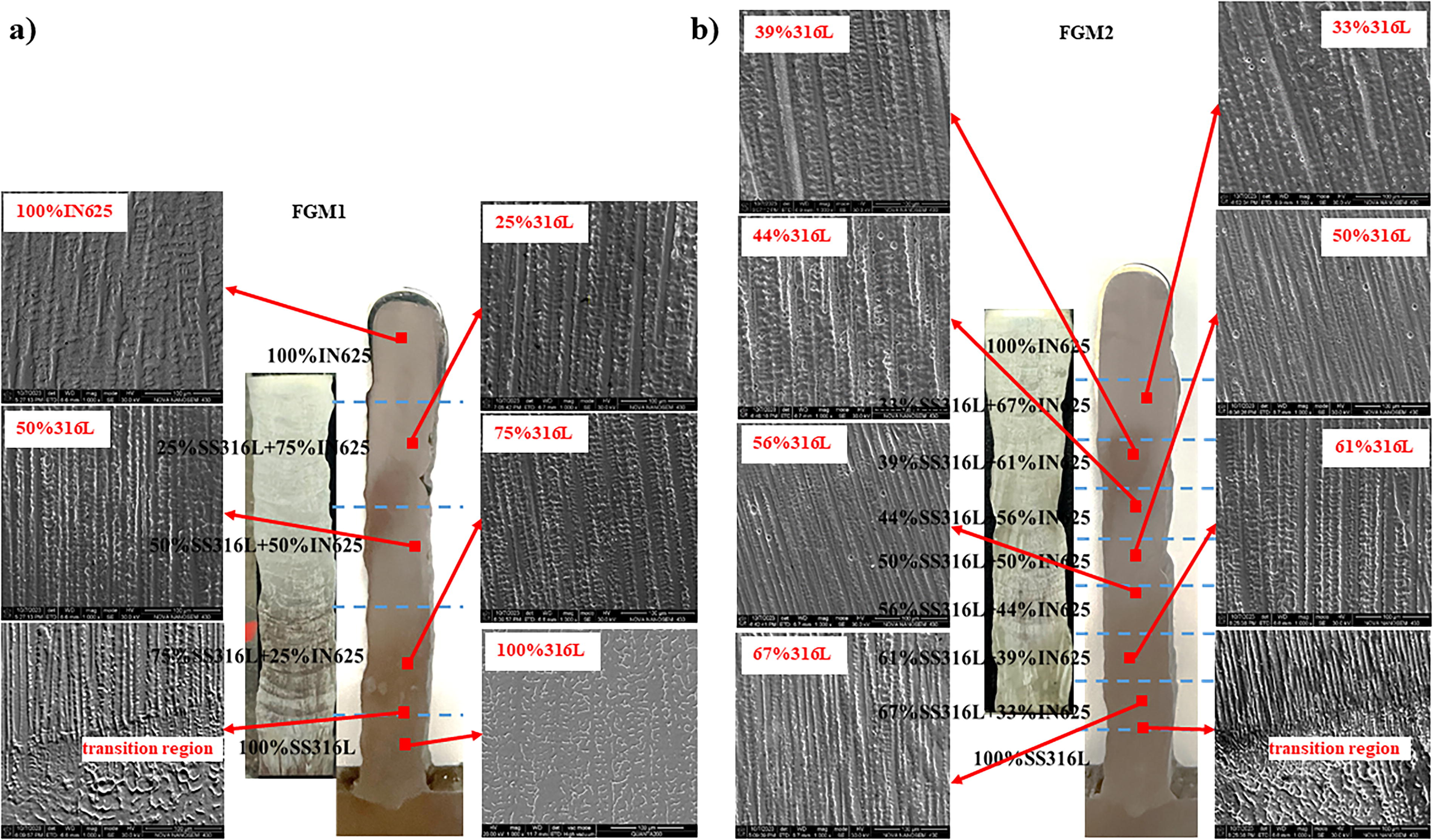
SEM microstructure and energy spectrum analysis diagram of samples;
Nevertheless, a notable difference in microstructure morphology was observed at the interface between the 75% SS316L and 100% SS316L regions when the Inconel 625 alloy was introduced. With the rise in Inconel625 content, there was a change in the element ratio, as shown in Figure 9a and b. The energy spectrum element ratio closely approximated the set ratio, suggesting a relatively uniform distribution of the mixed wires in MIG welding deposition. Furthermore, the microstructure of columnar dendrites suggests that the grains displayed a tendency for typical epitaxial growth along the deposition direction, with each region predominantly consisting of the face-centered cubic (FCC) austenite structure. Moreover, the bright white precipitates were observed to precipitate along the columnar crystal boundary in various regions, and this phenomenon will be further discussed by energy spectrum analysis.
Hardness and Composition distributions EDS along the building direction from the substrate to the last deposited layer of samples;
Figure 10 displays the EDS results for the 25% and 75% SS316L regions of FGM1, along with the 50%, 56%, and 67% SS316L regions of FGM2. Owing to the rapid solidification that occurs during the deposition process, the solidified microstructure in the gradient region comprised a primary phase and a small quantity of secondary phase. The examination of Figure 10b indicated the presence of prominent cracks in the 75% SS316L area, with crack propagation aligning with the direction of dendrite growth. In addition, the cracks were mainly located at the boundary of cellular dendrites. The EDS plots of the crack area indicated that the particles within the crack predominantly consisted of silicon (Si) and carbon (C) elements. The cause may have been the manufacturing sample experienced thermal cracks, SiC particles from the sandpaper into thermal cracks that developed in the manufacturing sample during the polishing process. The presence of carbides containing Nb and Mo was indicated by a notable enrichment of Mo, Nb, and C at the edge of the crack. This phenomenon was primarily attributed to the high affinity between Nb and C, and the ability of Mo to facilitate the formation of Nb and Mo carbides. 17 It is worth noting that the presence of brittle carbides could lead to grain deformation and cracking, a finding consistent with previous reports on the deposition of gradient material 304 L/Inconel 625 alloy using alternative methods. 18
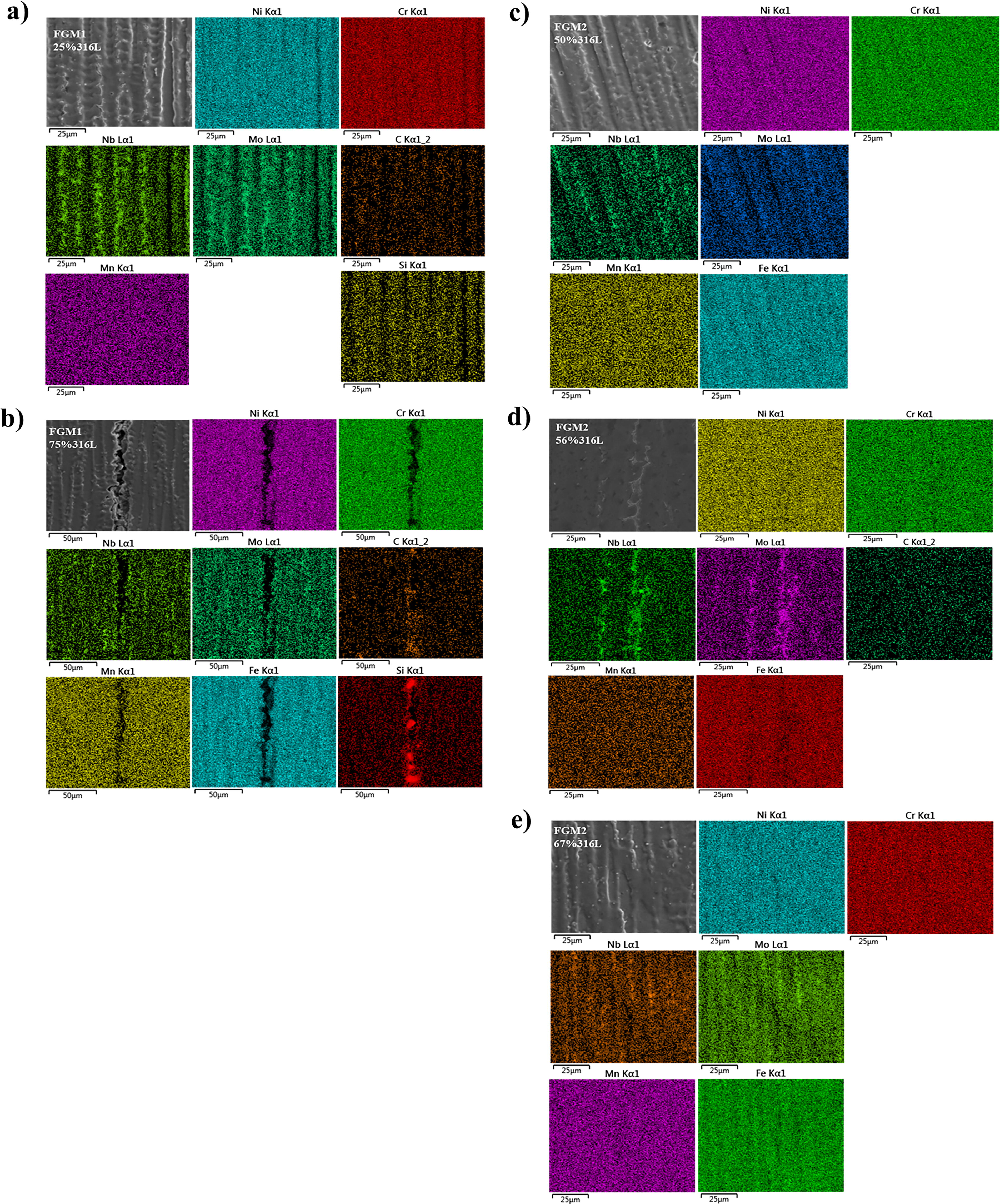
Energy spectrum analysis diagram of FGM1 and FGM2;
Moreover, the development of the crack was associated with the solidification A mode of the 75% SS316L region that was deposited, and the higher nickel content hindered the formation of δ-ferrite in this region. This inhibition of δ-ferrite formation played a role in preventing solidification cracks. 19 As a result, solidification cracks were more likely to form in the 75% SS316L area exhibiting an austenite microstructure. However, the AM process closely resembled heat treatment for each remelted layer, with each deposited layer undergoing a specific amount of heat treatment. Areas with high austenite content were susceptible to thermal cracking.
It is noteworthy that the increase in Inconel 625 content led to a corresponding increase in the number of precipitated phases. Conversely, no cracks were observed in the other areas of the two samples, as shown in Figure 10a and c–e. This phenomenon can be attributed to the reduction in carbon content provided by SS316L. The carbide content decreased with the addition of Inconel625, enabling the production of the Laves phase. Moreover, the deviation from the composition range of austenitic stainless steel in the gradient region, which contains more Inconel 625, led to a decrease in the content of carbides and the tendency to produce solidification cracks.
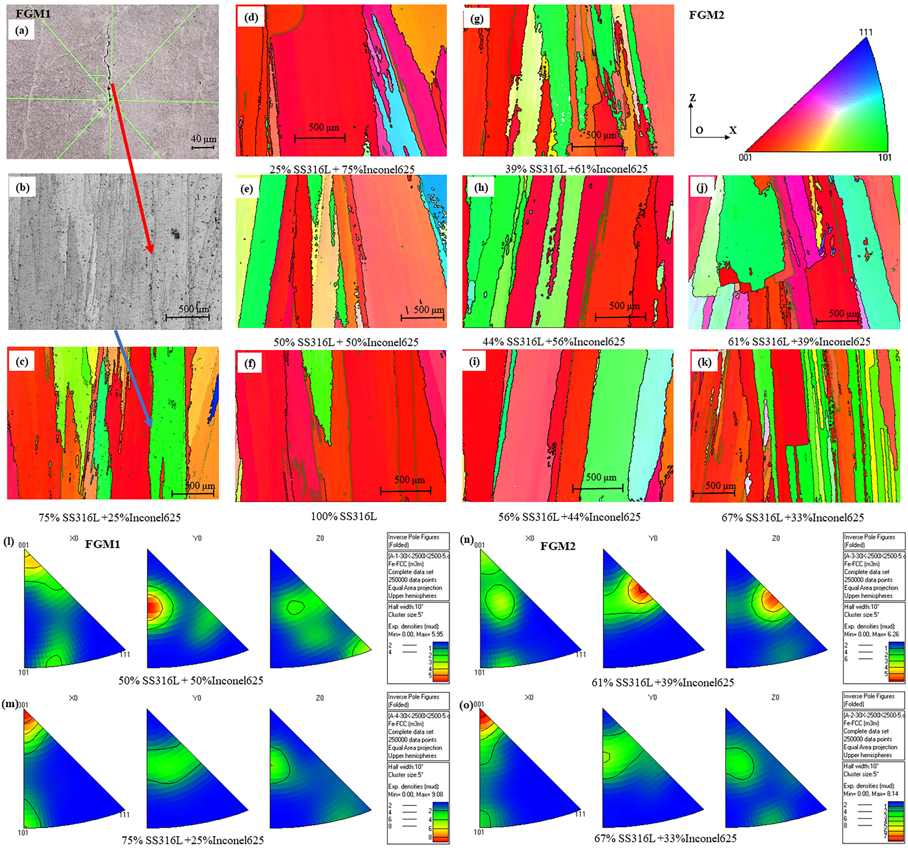
Figure 11 shows EBSD maps of different patterns and different gradients. There is only one FCC γ phase in the entire FGMs, exhibiting epitaxial growth of columnar crystals, which is consistent with the SEM observation in Figure 8. Most of the red and yellow inverse polarity figures (IPFs) in Figure 11c–k indicate that the grain mainly grows along the <001> direction of the building direction marked in the figure, while the green IPF indicates that it grows along the <101> direction. The <001> and <101> directions are austenite (FCC) and ferrite phases, respectively. Then the pole figures in Figure 11m and o also indicate that 75% SS316L/25% Inconel 625 and 67% SS316L/33% Inconel 625 have strong texture in the <001> direction, which is almost parallel to the direction of heat flow during solidification. Since SS316L and Inconel 625 are composed of austenite matrix with FCC lattice, 12 the manufacturing process from SS316L to Inconel 625 is accompanied by changes in chemical composition, the grain growth on the interface exhibits significant continuity and the same crystal orientation. The results showed that the grain was mainly columnar crystal, and no secondary precipitates were identified in the EBSD analysis.
EBSD grain orientation maps in FGM1
It is noteworthy that cracks were also detected in the 75% SS316L region of FGM1 by EBSD analysis in Figure 11a, located in the 8th to 11th layers. This indicates that the location of the cracks has undergone over eight reheating cycles during such thermal processing, then the dendritic growth and precipitation of secondary phases occurred. In contrast, the separation of secondary phases tends to cause cracks, and cracks will occur when the temperature exceeds the residual stress relaxation temperature. 20 Stress is usually caused by thermal accumulation due to multiple thermal cycles, in which the precipitation of secondary phases hinders the movement and regeneration of dislocations, resulting in stress concentration between dendrites and causing the material to fracture into cracks. 21 Cracks extend along the building direction and are mainly parallel to the <001>plane direction. Figure 11b shows that cracks are mainly located at the boundaries of columnar crystals. During AM, due to the rapid cooling and large thermal, dendrites grow along the building direction. Therefore, the expansion of cracks is almost parallel to the building direction. 10 This is because low-melting secondary phases and the matrix form a liquid film during eutectic melting under rapid solidification conditions, which can be pulled apart by stress to be a thermal crack.22,23
Figure 11a–c shows the EBSD results near the crack. The IPF results in Figure 11c indicate that there are significant differences in grain orientation on both sides of the crack. The direction of the red particles is almost parallel to the building direction, while the direction of the green particles shows a large angle with the building direction. The crack occurs at a large-angle grain boundary between dendrites, parallel to the growth direction of dendrites. The maximum texture intensity in Figure 11m is 9.08, clearly indicating its preferred grain growth direction. Thermal stress and residual stress are mainly caused by the formation of segregation and precipitation, which produce defects observed in the microscopic analysis described above. Therefore, the results of the EBSD analysis confirm that the crack defects mainly occurred at grain boundary dislocations between <001> and <101> planes.24,25 The presence of niobium-rich and molybdenum-rich precipitates along the grain boundary, and different cooling rates associated with rapid solidification and non-equilibrium processes could lead to the formation of defects in a specific transition zone near 75% SS316L/25% Inconel 625, which is the weak link of FGM.
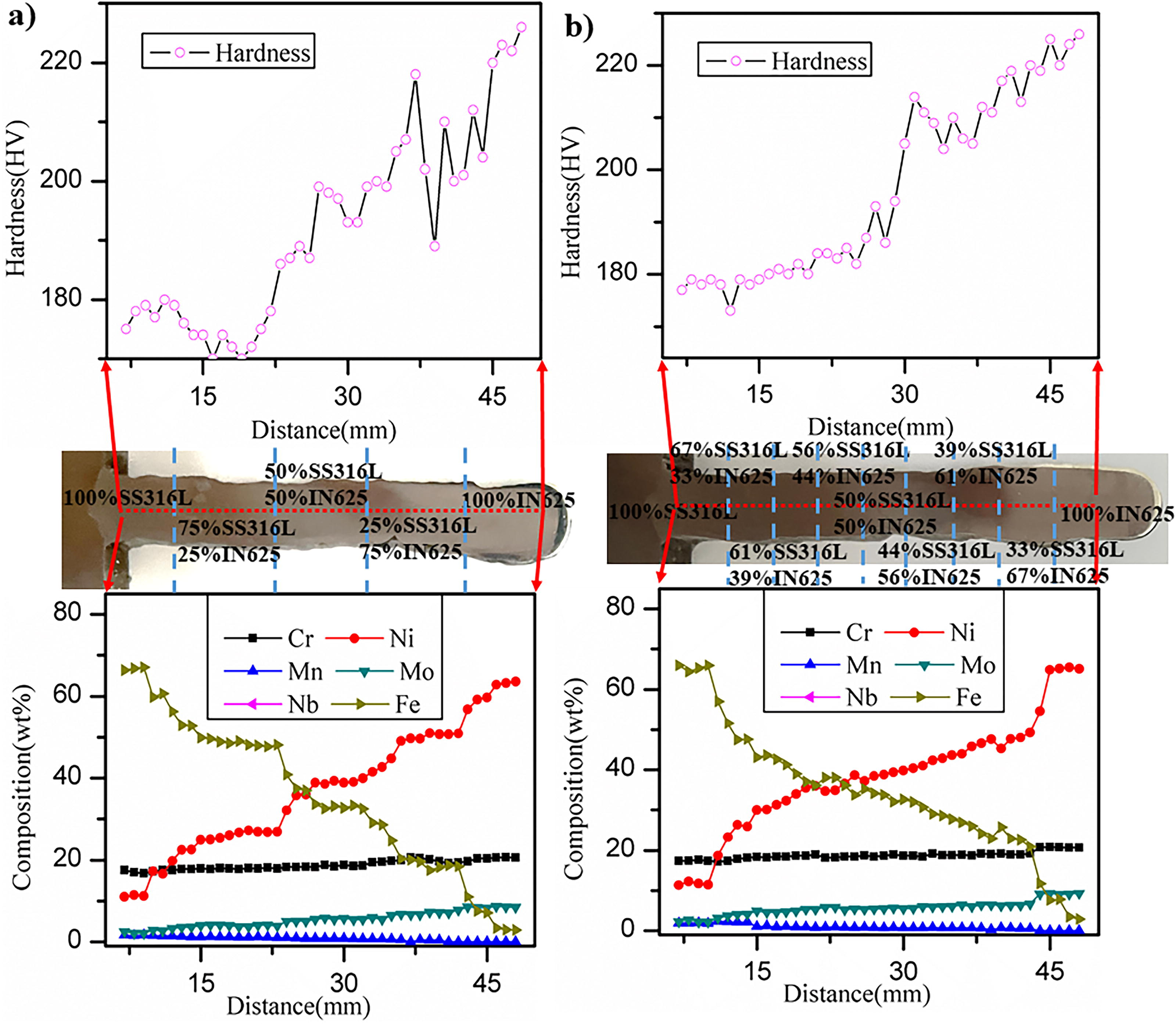
The Vickers hardness was measured along the center of the sample’s cross-section, and the element content curves were obtained using EDS, as depicted in Figure 9, respectively. The elements were distributed regularly in regions characterized by varying gradient ratios. The Fe content in the base metal was highest at the bottom position and gradually decreased towards the top position. This content was diluted to some extent as it passed through the graded zone, and ultimately, the Fe content in the surfacing layers decreased gradually. In contrast, the distribution of the Ni element was opposite to that of Fe, and there was a slight increase in the Mo element. The variations in other elements were not significant. The content of Mo and Nb within the dendrites of the deposition layers was found to be lower, while there was a slight enrichment of Ni and Cr between the dendrites. According to the hardness curves, the hardness of both samples exhibited a gradual increase. However, the curve of FGM1 showed significant fluctuations, suggesting a substantial variation in the performance of the gradient transition process. This indicates a susceptibility to failure, particularly at a distance of approximately 15 mm from the substrate. It was observed that the hardness decreased to 170 HV at a gradient of 75% SS316L, consistent with findings reported in references, 12 and, 13 thus validating the aforementioned microstructure analysis.
The average hardness values of various gradient areas in two samples are presented in Figure 12. It was observed that the overall average hardness of the two samples did not exhibit a significant difference. The average hardness exhibited slight variations at different gradients, particularly in the C region of the figure, which corresponded to the 75% SS316L gradient area of FGM1 and the 67% SS316L gradient area of FGM2. It was evident that the average hardness value of 173.5 ± 2.41 HV in the 75% SS316L gradient area of FGM1 was observed to be lower than in other areas, as well as in the 67% SS316L area of FGM2. This trend aligns with the results obtained from the hardness curves at different positions within the above region. The microhardness values of FGM1 (190.1 ± 12.2 HV) and FGM2 (186.8 ± 15.8 HV) exceeded the reported value for 316 L stainless steel (180.84 ± 2.7 HV) 26 but were lower than that for Inconel 625 (228 ± 4 HV) 27 both produced via single-material wire and arc AM (WAAM). These results demonstrate that the manufacturing process meets the FGM requirements.
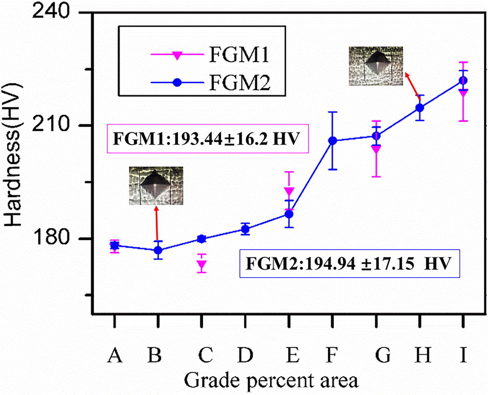
Average hardness values in different regions of FGM1 and FGM2. a, b, c, d, e, f, g, h and i represent 100% SS316L, 67% SS316L/33% Inconel 625, 61% SS316L/39% Inconel 625, 56% SS316L/44% Inconel 625, 50% SS316L/50% Inconel 625, 44% SS316L/56% Inconel 625, 39% SS316L/61% Inconel 625, 33% SS316L/67% Inconel 625, 100% Inconel 625 areas, respectively in FGM1, while a, c, e, g and i represent 100% SS316L, 75% SS316L/25% Inconel 625, 50% SS316L/50% Inconel 625, 25% SS316L/75% Inconel 625, 100% Inconel 625 areas, respectively in FGM2. FGM, functionally graded materials.
The average tensile strength and elongation for FGM1 and FGM2 were 550.8 ± 17.2 MPa and 46.4 ± 2.7%, and 562.3 ± 5.9 MPa and 51.2 ± 2.1%, respectively. When compared with the literature values for 316 L (507.6 MPa, 28 42.49 ± 2.95%, 15 ) and Inconel 625 (644.5 ± 68.5 MPa, 29 50%, 1 ) also produced via single-material WAAM, as well as with wrought alloy standards, the mechanical properties were within the expected range. Notably, the anisotropy in tensile strength was reduced compared to the two materials deposited separately, and the average tensile strength was within the acceptable range for both materials, adhering to the forging standard requirements. The histogram chart in Figure 13 a and b presents a comparison of the tensile properties at various positions of FGM1 and FGM2. The results indicate that the transverse tensile properties of each part of FGM1 were slightly inferior to those of FGM2, particularly at the H2 position. The SS316L content decreased from H1 to H5 positions, while the Inconel 625 content increased, leading to a gradual enhancement in its tensile properties. The performance of FGM1 exhibited a significant decrease to 507.53 ± 11.6 MPa in the 75% SS316L region, whereas FGM2 decreased to 538.8 ± 19.9 MPa in the 67% SS316L area. The performance of the two samples in longitudinal stretching closely resembled that of the transverse stretching result, and the tensile properties exhibited negligible anisotropy. This suggests that the method of manufacturing gradient materials by MIG welding was feasible, and the longitudinal performance also displayed a gradient.
Observing the stress-strain curves and the corresponding tensile fracture at the H2 position of FGM1 and FGM2, depicted in Figure 13c and d, it is apparent that the maximum tensile strength and elongation of FGM1 were lower than those of FGM2. This suggests that the tensile performance of FGM1 in the 75% SS316L region is inferior to the 67% SS316L gradient area of FGM2. This observation aligns with the hardness performance and the findings presented in Figure 12.

Tensile results and fracture morphology of different parts in FGM1 and FGM2;
The comparison of elongation results showed that the horizontal and vertical elongation are higher than the SS316L metal samples manufactured by the same method, 15 and the elongation of both metals is higher than that of forging. It shows that the plasticity of arc additive gradient material in this study is superior to that of single metal forging. Moreover, the plasticity of FGM2 is also better than that of FGM1, and the anisotropy can be ignored.
Upon examination of the micro-morphology of the fracture surface, it was evident that the fracture exhibited a distinct equiaxed dimple morphology, characteristic of a typical ductile fracture in Figure 13c and d. It is evident that the larger and deeper dimples in Figure 13d indicate a significant level of plastic deformation that occurred during the formation of the dimples. Consequently, a greater amount of energy would be absorbed during the process of fracture, leading to improved toughness. This observation is consistent with the elongation result depicted in Figure 13a. The cracked area is prone to failure and has poor plasticity, which is consistent with the microscopic analysis.
Conclusions
This study proposed a double-wire MIG welding process for AM, aimed at producing SS316L/Inconel 625 FGMs. Two thin-walled structures, FGM1 with a 25% gradient and FGM2 with a 5% gradient were fabricated by controlling the feeding speeds of the two wires. Subsequently, an examination was conducted to analyze the variations in morphology, microstructure, and properties in the direction of construction, with particular focus on the 67% and 75% SS316L stainless steel regions. The study’s conclusions are as follows:
The process effectively produced well-formed structures of different gradient materials, without any macroscopic cracks or flow defects. The morphology of the arc and side molten pool, as well as the waveforms of the depositions, suggest that the deposition process was relatively stable. The deposition rates of FGM1 and FGM2 were 53% and 65.4%, respectively, suggesting that a uniform transition gradient resulted in a more stable deposition process and increased forming efficiency when switching two wire feeding speeds. The microstructure exhibited columnar structures, with the addition of Inconel 625 alloy resulting in a significantly different morphology. The presence of Mo promoted the precipitation of Nb and Mo carbides, while noticeable cracks were detected in the 75% SS316L region, exhibiting propagation in alignment with the direction of dendrite growth and primarily situated at the boundary of cellular dendrites. The EBSD analysis revealed that the predominant orientation of grain growth was <001>. The hardness and horizontal tensile properties of the two samples exhibited a gradual upward trend from the substrate to the top. However, the curve of FGM1 showed significant fluctuations, and the properties of the 75% SS316L gradient apparently decreased. The tensile fracture of the two depositions exhibited typical ductile fracture behavior. The minimum hardness and tensile values of FGM1 fell within the 75% SS316L range, measuring 173.5 ± 2.41 HV and 507.53 ± 11.6 MPa, respectively. Similarly, for FGM2, the values were within the 67% SS316L region, with measurements of 177 ± 2.34 HV and 538.8 ± 19.9 MPa.
In conclusion, it is advisable to avoid positioning the gradient selection of stainless steel and nickel alloy materials in close proximity to the 75% SS316L region. Instead, a gradient range of less than 67% SS316L can be chosen as the transition ratio for two dissimilar materials. The manufactured FGMs in this study were superior to the wrought value, and the mechanical properties were higher than SS316L and lower than Inconel 625 manufacturing of single material, and the anisotropy was not obvious, in addition, the cost of FGM is lower than that of single Inconel 625 material. This achievement can have a significant impact on the extension of service life and the prevention of premature failure in disparate structural components.
Footnotes
Authors’ Contributions
W.W.: Methodology (lead), Writing—original draft preparation (lead), Project administration (lead), Funding acquisition (lead), Writing—review and editing (equal), Providing ideas (equal). P.Y.: Methodology (supporting), Project administration (supporting), Funding acquisition (supporting), Writing—review and editing (equal), Providing ideas (equal). C.W.: Writing—original draft preparation (supporting), Data curation (supporting). Z.L.: Data curation (supporting), Writing—review and editing (equal), Providing ideas (equal). W.X.: Project administration (supporting), Funding acquisition (supporting).
Author Disclosure Statement
No competing financial interests exist.
Funding Information
This work was supported by the Project of the Educational Commission of Guangdong Province of China under Grant number 2020ZDZX2019; the Talent Introduction and Scientific Research Launch Project under Grant number 2021SDKYA086; and the Key Construction Discipline Research Ability Improvement Project of Guangdong Province, under Grant number 2021ZDJS027.