
Abstract
The high plateau and cold environment can easily lead to ice formation on the engine lip and other parts of the aircraft, increasing the flight risk. Conventional aircraft electrothermal anti-icing/de-icing utilizes flat structures for heating and lacks the ability to flexibly fit complex surfaces. In this study, based on the programmable design of electric power density of continuous wire composite thermoplastic polymer (WCTP) heated film, an optimization model for the WCTP electric power density is established. A fabrication method for curved composite heating plates (CHP) combining 3D printing and molding has been proposed. The experimental results show that the power density deviation of the curved CHP is a mere 1.25% and the temperature of the curved CHP can swiftly reach 50°C within 30 s under the extreme condition of −40°C, indicative of its rapid warming capability.
Introduction
When an airplane flies through clouds with low temperatures, the airflow-facing components such as the leading edges of the wings and tail, the engine lip, the airspeed tube, and the antenna cover are susceptible to ice formation. The accumulation of ice on these critical component surfaces can lead to alterations in wing shape, reduction in lift, augmentation of drag, and diminished aircraft stability.1–3 Therefore, it is crucial to examine the technology used to prevent or remove ice from the complex surfaces of an aircraft.
Aircraft anti-icing/de-icing methods are mainly classified into two methods: active and passive. 4 Active anti-icing/de-icing uses energy from external sources 5 and the main methods include pneumatic de-icing, 6 hot air de-icing, 7 and electric heating anti-icing/de-icing, 8 while passive anti-icing uses physical or chemical properties of a substance to prevent icing and the main methods include coating anti-icing.9–11 Among them, electric heating anti-icing/de-icing has received a lot of attention due to its advantages such as precision controllability, stability, and high efficiency.12,13 Electrically heated anti-icing/de-icing systems use strip or thin-film heating elements embedded in the structure to continuously or periodically heat the aircraft surface so that the temperature of the aircraft surface exceeds the icing temperature point to achieve the purpose of anti-icing/de-icing.13–16 They are classified into two types: internal heating and external heating anti-icing/de-icing methods. The external heating method involves applying electric heating material directly onto the outermost surface of the aircraft and heating it directly at the interface where ice accumulation occurs. The internal heating method generates heat from the embedded electric heating element and then transfers it to the outermost surface of the aircraft through the substrate, which will cause some loss during the heat transfer process and is suitable for the parts where the outer surface requirements are high and the external surface heating cannot be used.8,17 Commonly used heat-generating materials in electric heating are carbon nanotubes (CNTs),18,19 graphene, 20 nanowires, 21 and metal elements.17,22 For example, Rashid et al. 23 created an electric heater using CNT films polymerized polyethylene terephthalate (PET) substrate for effective anti-icing/de-icing. However, the general electric heating structure is mainly for flat structures, which makes it difficult to meet the demand for anti-icing/de-icing of complex surfaces of aircraft.
In recent years due to the constant development of manufacturing technologies, many different electro-thermal anti-icing/de-icing strategies have emerged to solve this problem. Jo et al. 24 developed flexible copper fiber heaters using electrostatic spinning and plating techniques and the heaters can be transferred to structurally complex surfaces. Mohseni et al. 17 employed discrete constantan thermal components to prevent icing and de-icing wind turbine blades and aircraft wing structures. Meanwhile, the flexible electric heating structure enables it to conform to complex curved surfaces to a certain extent. Xia et al. 25 manufactured a flexible pressure-sensitive adhesive graphene-based composite heater from several graphene nanosheet papers and styrene-butadiene rubber layers. Due to its flexibility, this heater can be applied to complex-shaped surfaces. Zhao et al. 26 developed a biaxial stretchy electric heating film by combining conductive rubber material with stretchable electrodes manufactured by silver plating on fiber cloth, resulting in a highly flexible deformation capability and heat generation performance. Improvement of the heat conductivity or electrical conductivity of polymers by nanofillers can also play an important role in the anti-icing/de-icing of complex surfaces. 27 Zhao et al. 28 created electrothermal coatings by adding multiwall CNTs into a polyurethane matrix. Li et al. 29 fabricated photothermal nanocoatings by spraying TiN nanoparticles and SiO2 particles over complicated cable surfaces to provide effective anti-icing/de-icing. Besides, 3D printing technology, as an emerging manufacturing method, is being applied in electric heating anti/anti-icing systems to address icing problems. However, research on its anti/anti-icing performance for complex surfaces is still relatively limited.
As a result, the article presents a method for designing and fabricating a 3D printing programmable wire composite thermoplastic polymer (WCTP) a continuous WCTP electric heating film that can be applied on complex surfaces. The study explores the programmable design of WCTP electric power density, utilizing a combination of 3D printing and high-temperature molding to manufacture a curved WCTP, which is then used as a heating layer to cure a curved composite heating plate (CHP). Subsequently, the consistency of power density design and fabrication, temperature uniformity, and thermal performance of the curved CHP were then analyzed. Additionally, the stability of the overall panel operation after damage to one of the curved CHP’s branches and the feasibility of using it as a heating element. This novel approach presents a promising avenue for addressing the anti-icing/de-icing of aircraft complex surfaces.
Programmable Wire Composite Thermoplastic Polymer Design
Wire composite thermoplastic polymer working principle
The structure of WCTP is shown in Figure 1b, where the wire is embedded in the thermoplastic polymer substrate and a closed loop is formed by connecting the wires at the junction through copper tape. The equivalent circuit of the WCTP is shown in Figure 1c, each branch of the wire is equivalent to a resistor and the overall structure of the WCTP can be equated to a parallel circuit, which generates Joule heat as a heat source through electricity and then transfers it to the ice layer via heat conduction, thereby facilitating the anti-icing/de-icing function. Because WCTP is more fragile when directly used as an anti-icing/de-icing element, it is generally put as a heating layer in the CHP to improve its stability. Figure 1a shows the structure of the CHP, which is made up primarily of a heating layer, two insulating layers, a windward layer, and a leeward layer. The insulating layers prevent the WCTP from contacting other conductive substances, the windward and leeward layers provide resistance to external impacts to ensure the stability of the WCTP during operation. Notably, the windward layer is thinner than the leeward layer to enhance anti-icing/de-icing efficiency. Additionally, a thermocouple is placed in the insulation layer to facilitate subsequent temperature measurement. There is an ice layer that forms on the outside of the windward layer due to environmental factors.
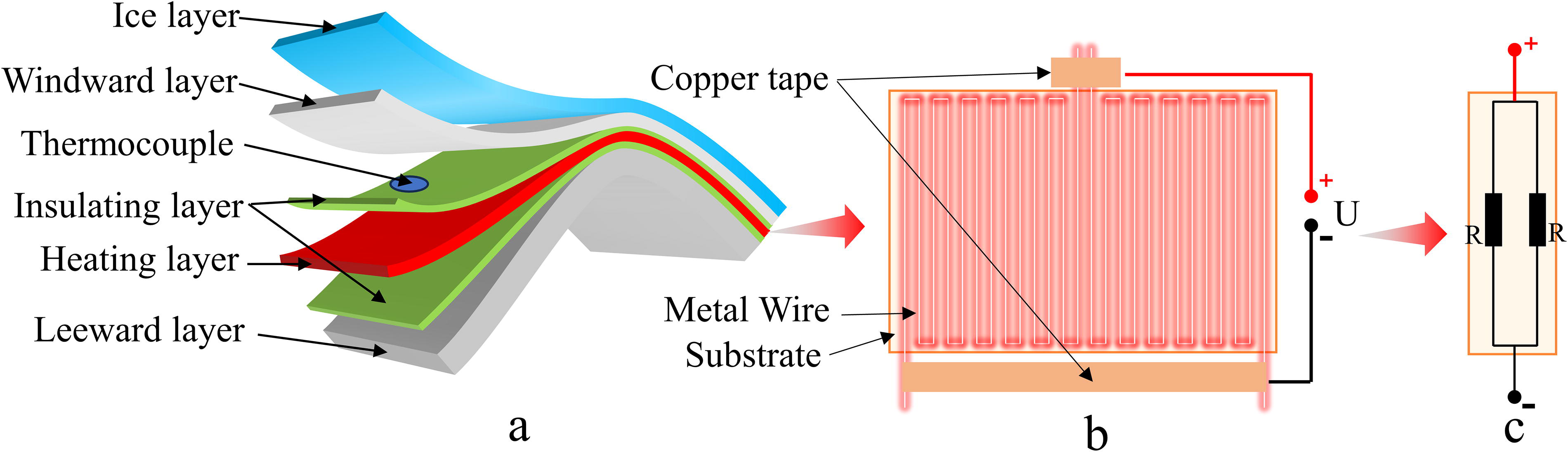
Schematic of WCTP.
The Joule heat generated by CHP can be estimated by the following equation:

Where
The total heat

According to the law of conservation of energy, WCTP diffusion loss of heat is equal to the energy damaged in the process of heat conduction, convection, and radiation. The absorbed heat

Where c is the specific heat capacity of the materials in the windward and leeward layers;
By equating Equations (1)–(3), the following expression is also obtained:

Equation (4) shows that the final temperature transferred to the ice layer and the electric power density of WCTP are strongly connected, which influences the warming rate of the windward layer and the final balance temperature. The actual use of the working circumstances will be determined first by the target power density of WCTP and its operating mode, thus it is vital to fabricate WCTP that meets the power density requirements.
Optimized modeling of power density programmable wire composite thermoplastic polymer
Due to the stability of the resistance value of the wire and the flexibility of the 3D printing process, the electric power density of the WCTP can be adjusted flexibly to a large extent by changing the printing pitch, embedded trajectory, wire material, wire diameter and other factors.
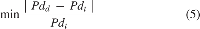
For the design of WCTP, the ultimate goal is to minimize the deviation of WCTP design power density (
The design power density of WCTP and the current


Where U is the supply voltage of WCTP; S is the area of WCTP; R is the total resistance value of WCTP; and N is the number of branches connected in parallel.
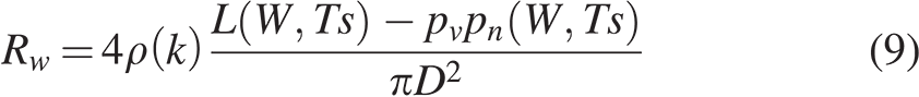
The relationship between the total resistance value of WCTP (R) and the total resistance value of the continuous wire (

Where α indicates the ratio between
By equating Equations (5)–(9), The final optimization model can be expressed as:


So far, the programmable principle for WCTP electric power density has been summarized into a parametric optimization model, with five design variables represented by X= [
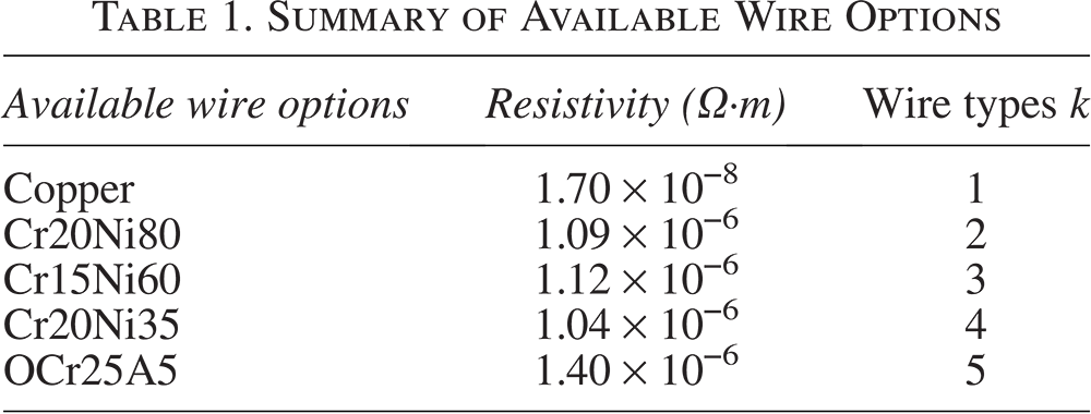
Multiple feasible solutions for a certain electric power density of WTCP can be produced by setting the beginning conditions of the optimization model and solving it, as well as feasible solutions for other electric power densities of the same shape. For example, consider the design of a 50 × 50 mm square WCTP, the supply voltage is 28V, and the target power density of 1.0 W/cm2, 1.2 W/cm2, 1.4 W/cm2, and 1.6 W/cm2, respectively. Available wire options are shown in Table 1. The design results in Figure 2 are obtained by solving the optimization model. Among them, Figure 2a and b represents the three feasible design schemes for a target electric power density is 1.0 W/cm2, while Figure 2a and c represents the feasible design schemes when the target electric power density is 1.0–1.6 W/cm2. It can be seen that the programmable design of WCTP can get the results to satisfy different power density targets and there are also a variety of design options under the same power density target, demonstrating a high degree of design flexibility and can be adapted to a variety of applications.
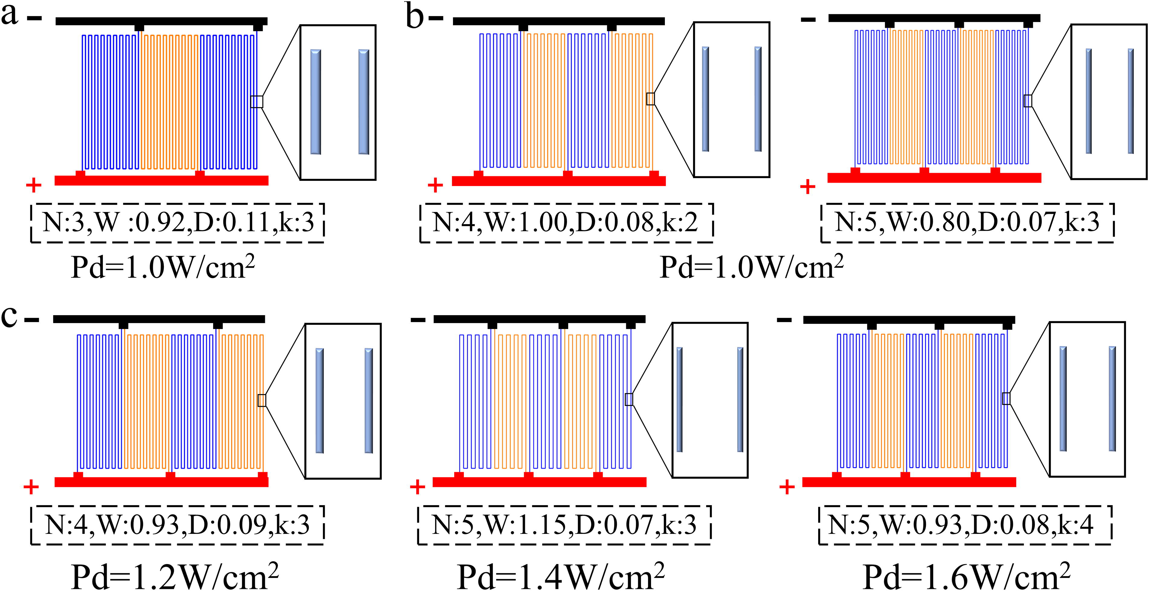
50 mm × 50 mm square WCTP programmable design results (the black dashed boxes indicate the values of the design variables, where the unit of W and D is mm).
Summary of Available Wire Options
Curved Composite Heating Plate Fabrication Process
Wire composite thermoplastic polymer 3D printing process
In this article, a two-inlet and one-outlet printer structure is utilized, including components such as an extruder, heat sink, heating block, and nozzle. With the help of the heating block structure proposed by Yehia et al., 15 which features two inlets, one inlet serves for the transportation of thermoplastic filament, while the other inlet facilitates the feeding of the wire using a metal tube, as depicted in Figure 3a. During the printing process, the filament is continuously fed into the heating block through the extruder and melts inside the heating block. Meanwhile, the wire is continuously drawn into the interior of the heating block through the adhesive force with the platform and the wire and the molten filament are combined inside the heating block, so that the filament wraps around the wire, which is then extruded together through the nozzle and then quickly solidified to form the WCTP, as shown in Figure 3b.
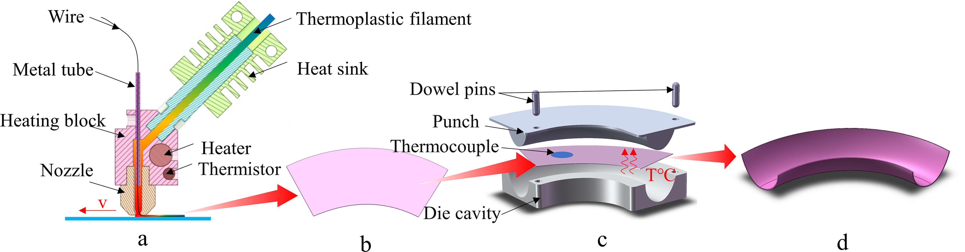
Curved WCTP fabrication process diagram.
Curved wire composite thermoplastic polymer fabrication process
Although 3D printing offers significant fabrication flexibility, molding curved WCTP in a single pass proves challenging due to the complexity of curved surfaces and the limitations of printer structure size and shape. Therefore, this article proposes a simple fabrication approach for curved WCTP. Thanks to its thermoplastic substrate, WCTP can undergo secondary deformation by heating the substrate to a softening temperature post-molding. This allows for plastic deformation of the WCTP under the mold’s squeezing action. Upon cooling and subsequent substrate recurring, the WCTP restores its original strength and hardness, resulting in the desired curved WCTP shape.
At the same time, because the WCTP has the ability to self-heating, no additional external energy input is required during the molding process of curved WCTP, which significantly simplifies the process, as depicted in Figure 3c. The prepared WCTP is laid flat on the surface of the die cavity and a thermocouple is placed on the plane of the WCTP to enable real-time temperature sensing. After the WCTP is activated to generate Joule heat, the substrate reaches the softening temperature. Subsequently, the punch gradually descends and upon complete closure of the mold, heating ceases. As the temperature cools down to room temperature, the curved WCTP is removed from the mold, as shown in Figure 3d.
Curved composite heating plate curing process
To ensure high stability during usage, the prepared curved WCTP serves as a heating layer in the curved CHP depicted in Figure 1a. The windward and leeward layers need to have the ability to withstand the external environment, usually using glass fiber prepreg. Due to the glass fiber is not conductive and the same material having a similar coefficient of thermal expansion, the same glass fiber prepreg is used for the insulation layer, and the curved CHP has a higher stability after layup and curing. After the layup is completed, the curved CHP is insulated and pressurized in a hot press tank and the curved CHP is finally cured and fabricated.
Experimental Verification
Design of curved wire composite thermoplastic polymer for aircraft inlet lips
In this article, the design of WCTP is simulated on the curved surface of the lip of a specific section of aircraft inlet lip, with its shape and 3D projection shown in Figure 4a and the target power density is 1.6 W/cm2. Additionally, the mean curvature is shown in Figure 4b, all of which are positive, indicating that the overall shape of the WCTP is a convex surface. Figure 4c depicts the Gaussian curvature, which is positive on the outer side and negative on the inner side, suggesting that the outer side is similar to an ellipsoid surface and the inner side to a saddle surface, both of which belong to a complex hyperboloid surface. With the help of CATIA, the surface is unfolded into a plane, as seen in Figure 4d and the plane area measures 37.74 cm2.
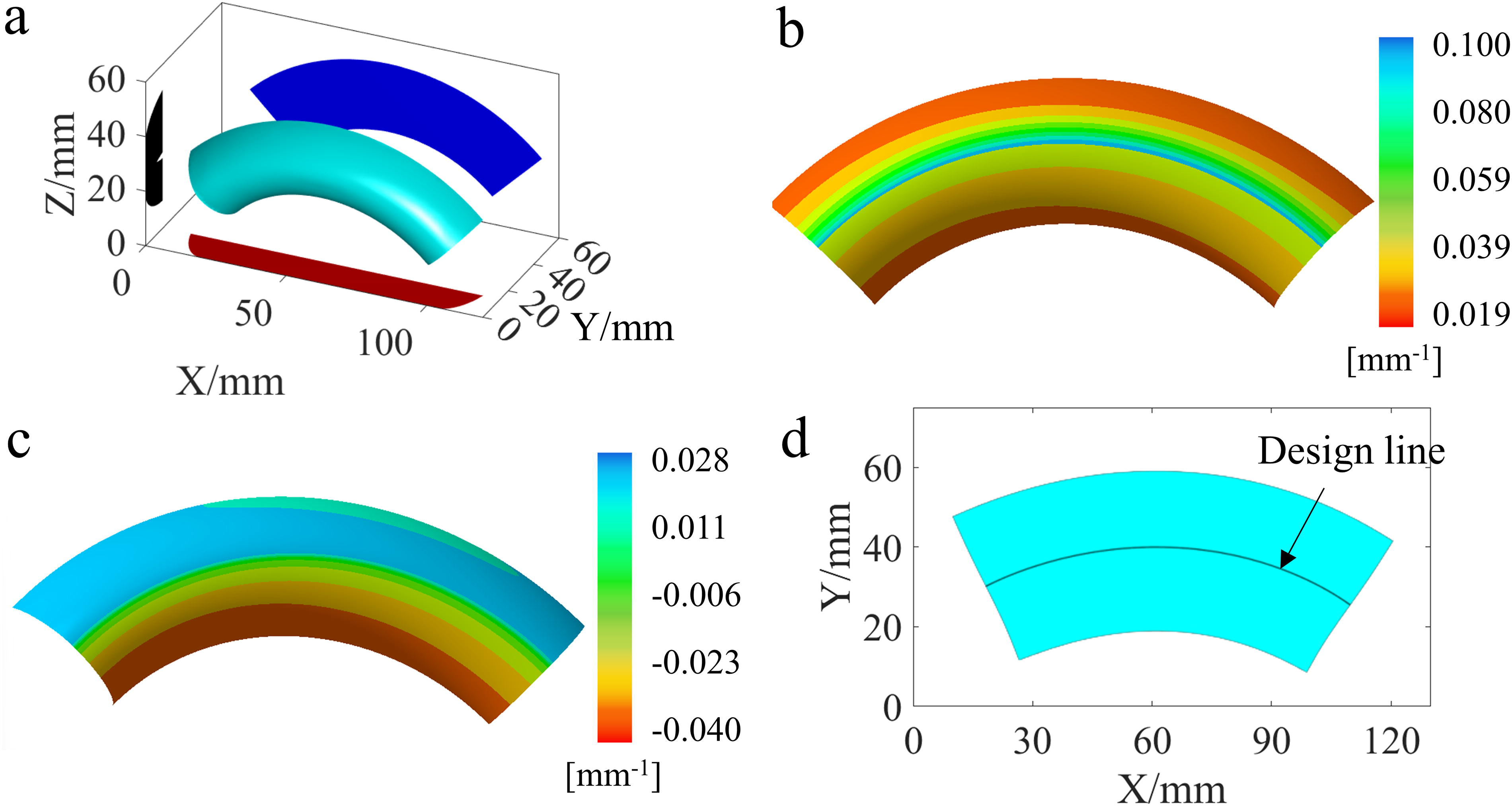
Aircraft inlet lip model.
Then the WCTP’s electric power density is designed. Because the airplane’s DC supply voltage is 270 V or 28 V,
30
to avoid excessive onboard power consumption when the curved WCTP is in operation, this article chooses 28VDC as the WCTP supply voltage. The wire type
Subsequently, the optimization model is solved by genetic algorithm, the number of populations is set to 50, the selection method is roulette wheel selection, the crossover method is scatter crossover, the crossover probability is 0.8, the mutation algorithm is Uniform mutation, and the proportion of mutation is 0.01. The iteration process is shown in Figure 5a, where the final average fitness reaches 4.48% after 35 iterations, the best fitness function value is only 0.19%. Meanwhile, the subsequent iteration fluctuations are stable, indicating that the algorithm has obtained an optimal solution. The individual values of this solution are shown in Figure 5b, which means that a 0.1 mm diameter Cr20Ni80 wire with a print width of 0.95 mm is used and divided into six branches for the fabrication of the WCTP and the final print trajectory is shown in Figure 5c.
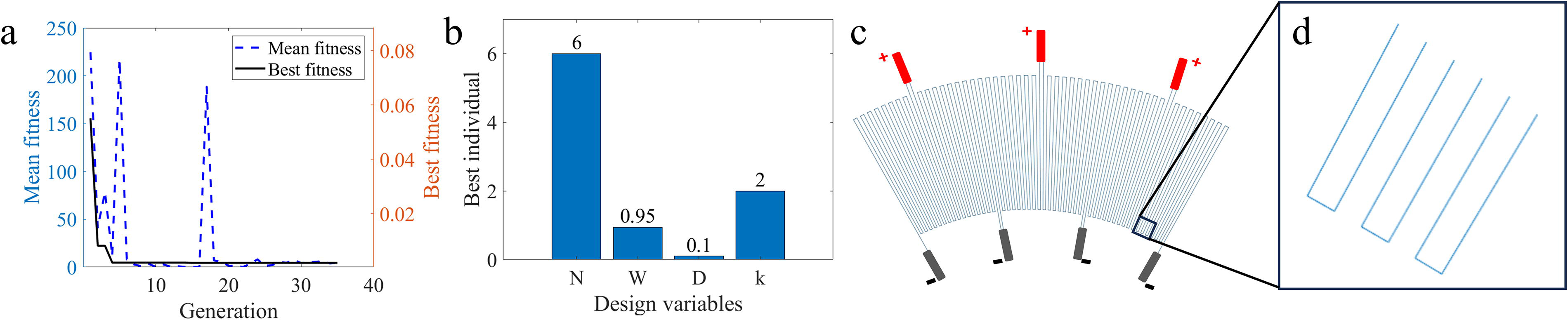
WCTP power density design result diagram and trajectory diagram.
Fabrication of Curved Composite Heating Plate for Aircraft Inlet Lips
Polycarbonate PC (provided by Attoblue) was selected as the WCTP’s substrate, which can withstand temperatures up to 100°C and has good plasticity as well as heat resistance. 31 Using 0.1 mm diameter Cr20Ni80 wire (provided by Changzhou Bayi Resistance Factory), the WCTP was 3D printed according to the designed trajectory, as shown in Figure 6b, and its local enlargement is shown in Figure 6a, which shows that the wire spacing is uniform and the surface quality is good. Then, based on the shape of the curved surface of the lip of a specific section of the aircraft inlet lip, construct the mold required for curved WCTP molding, switch on the 28V power supply, wait for the PC to exceed the softening temperature up to 120°C, and slowly drop until it closes. Wait about 1 min, turn off the power source, wait for the temperature to decrease to room temperature, and then carefully remove the punch to produce the curved WCTP, as shown in Figure 6c. Finally, the curved WCTP is embedded into the CHP as a heating layer and the windward, leeward, and insulating layer layers are made of glass fiber/epoxy resin prepreg EW100/IS1302 (provided by Tianjin Aisda Aerospace Science and Technology Co., Ltd.). The windward layer consisted of 6 layers and the leeward layer comprised 14 layers, each with a thickness of 0.1 mm. After the layers are laid, the temperature is raised to 130°C by applying four atmospheres of pressure through the hot press tank, followed by 2.5 h of heat treatment. After this process, the curved CHP was finally formed, as shown in Figure 6d.
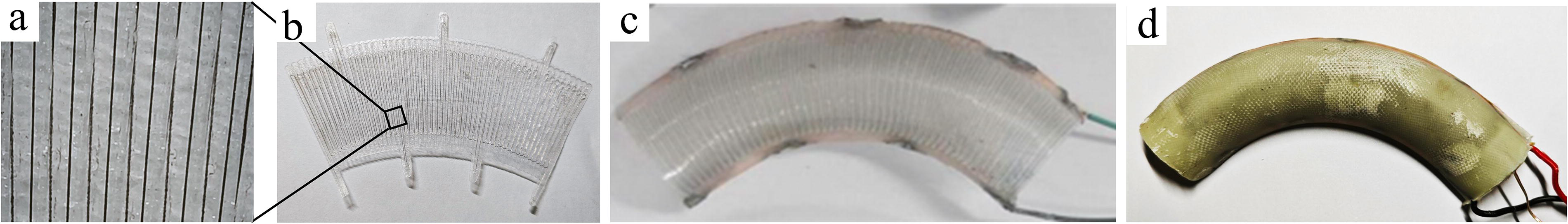
Physical images of WCTP and CHP
Results and Discussion
Electric power density analysis of curved composite heating plate
The heating element of the curved CHP consists of wire and its resistivity changes with temperature, leading to fluctuations in the actual electric power density during operation. Because the electric power density of the WCTP is considered in the programming of the electric power density of the room temperature and the electric power density of the nonelectrified conditions, the electric power density test of the curved CHP is also carried out in this work. Using a multimeter to test the resistance of the curved CHP is 12.82Ω and under the working voltage of 28 V, its actual electric power density is 1.62 W/cm2 as calculated by Equation 6. The slight deviation from the target power density of 1.6 W/cm2 can be attributed to several factors. First, although the design takes into account the existence of the wire retraction of the 3D printing WCTP, the length of the retraction at each time will fluctuate within a certain range, which makes it difficult to accurately compensate for these variations. Furthermore, the additional wire drawn to meet the parallel trajectory design may lead to changes in the resistance value, which in turn affects the change in the actual electric power density. Nevertheless, the deviation between the actual power density and the target power density is only 1.25%, demonstrating the high engineering and fabrication consistency of the curved CHP, as well as the feasibility and stability of the 3D printed programmable power density WCTP, which can meet the demands of the actual working conditions of anti-icing/de-icing.
Temperature uniformity analysis of curved composite heating plate
The thermal infrared image of the curved CHP is shown in Figure 7, under room temperature conditions with an electric power density of 1.6 W/cm2 and natural convection. Figure 7a and b represents the thermal infrared images of the curved CHP with the heating time of 5 s and 15 s, respectively. As the energization time rises, the heat is continuously generated in the wires, leading to the warming up of the curved CHP due to heat conduction. The temperature rise rate inside the curved CHP is higher than that on the outside, attributed to the smaller heating print width on the inner side and the larger print width on the outer side during the printing process, as evident throughout the warming-up process. But as time rises, the temperature continues to transfer to the outside and the overall temperature uniformity has been improved. At the same time, because the 3D printing wire arrangement is denser, the overall temperature distribution of the curved CHP is more uniform. Throughout the entire heating process, the temperature difference within the central area of the curved CHP remains within 10°C. Additionally, if the external proportional-integral-derivative (PID) temperature control device sets its heating temperature of 50°C, through repeated on and off heating, heat continues to diffuse, and the final overall temperature uniformity of the CHP will be further improved, as shown in Figure 7c. However, the edge of the temperature will still be lower than the center of the temperature, which is due to the edge of the part of the direct contact with the air increasing the loss of heat and ultimately the center of the region for the difference between the temperatures in the 5°C or less. It is worth noting that, due to the parallel relationship between the branches of the CHP, damage to one branch does not affect the normal operation of the other branches, as shown in Figure 7d, demonstrating that it can retain some anti-icing/de-icing ability in the case of unforeseen or harsh conditions.
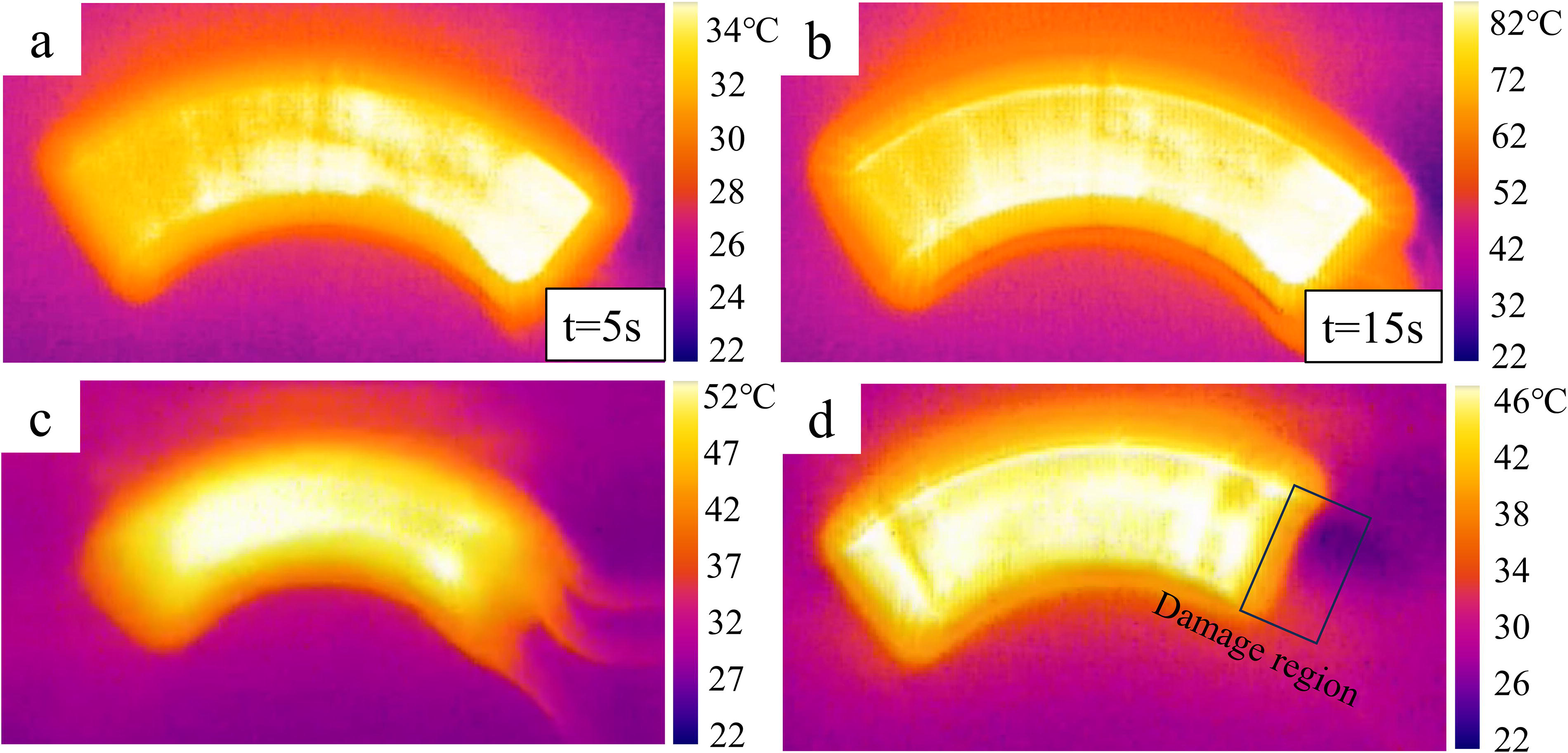
Infrared image of the CHP.
Electrical heating properties of curved composite heating plate
The electrical heating properties of the curved CHP are shown in Figure 8, where the temperature rise curves of the windward layer of the CHP are measured under different low-temperature operating conditions and power densities of 0.3 W/cm2, 0.8 W/cm2, and 1.6 W/cm2, respectively, by giving different operating voltages. Figure 8a–c displays the temperature rise curves at −20°C, −30°C, and −40°C ambient temperature, respectively. Within the depicted heating time range, the temperature shows an approximately linear increase. As the power density increases, the rate of heating K also rises significantly. At −30°C, heating power density of 1.6 W/cm2 corresponds to a temperature rise rate of 3.99°C/s, which is 6.1 times that of 0.3 W/cm2. Furthermore, it should be noted that K at the same power density exhibit only minor differences across different ambient temperatures. This is primarily due to the relatively stable thermal conductivity of the CHP under consistent conditions, resulting in similar temperature rise rates.

Electrical heating properties of the curved CHP (The symbol K represents the rate of heating and its unit is °C/s). Electrical heating curves at
Figure 8d shows the variation of the ratio of temperature change
Conclusions
In this study, we propose a novel method for anti-icing/de-icing of complex aircraft surfaces, where a WCTP electric heating film is fabrication by 3D printing and a CHP is further formed by utilizing high-temperature molding. The optimization model of WCTP design based on electric power density is explored, which can realize the design of WCTP to meet the target electric power density under specific voltage and specific shape, showing high design flexibility. The electrical power density of the fabricated curved CHP differed from the target by only 1.25%, demonstrating excellent design and fabrication consistency. In addition, the curved CHP can not only be on complex surfaces for efficient heating, such as in the environment of −40°C, 1.6 W/cm2 power density of the curved CHP works 10 s up to the temperature above the melting of the ice, and 30 s temperature of up to 50°C, but also damage to one branch will not affect the heating of other branches, showing great electric heating properties and work stability. The WCTP heated film fabricated by this method is well-suitable for complex surfaces that require anti-icing/de-icing in the aerospace field.
Footnotes
Author Disclosure Statement
No competing financial interests exist.
Funding Information
The work was supported by the National Natural Science Foundation of China (grant no. 52275255) and National Key Research and Development Program of China (grant nos. 2023YFB4603901 and 2023YFB4603900).