
Abstract
As a post-processing process of additive manufacturing, laser remelting can greatly improve the quality of laser selective melting formed parts. It is of great significance to study the influence mechanism of laser remelting process for the development of laser selective melting technology. Due to the rapid and microscopic evolution of rough surfaces during laser remelting, it is extremely challenging to analyze them using experimental methods. In this paper, based on the level set method, a multi-physics coupled finite element model is established to simulate and analyze the evolution process of rough surface during laser remelting. The model comprehensively considers the influence of energy density, Marangone effect and fluid mass transfer on surface morphology evolution. Through numerical simulation, it is found that in the process of laser remelting 316L stainless steel, the Marangoni effect plays an important role in the shape evolution of rough surface. Due to the fluid flow under the Marangoni effect, the uneven surface becomes smooth, and the surface roughness is improved. The effectiveness of the simulation is verified by experiments. The experimental results show that the surface roughness after laser remelting is reduced to different degrees, and the Ra and Sa values of the surface roughness are reduced by 54.4% and 68.3%, respectively, which is consistent with the trend of the simulation results. In addition, the changes of the roughness under different laser remelting power and scanning speed were analyzed by numerical simulation.
Introduction
Selective laser melting (SLM) forming technology is one of the most promising metal additive manufacturing technologies, 1 which realizes high-precision and integrated forming of metal parts based on the layer-by-layer fine powder laying of powder bed and layer-by-layer melting and stacking of laser beam. 2 This process method is especially suitable for the manufacturing of metal parts with complex structures, and has the advantages of short design and manufacturing cycle and easy to achieve lightweight, etc. It has been widely used in aerospace, biomedicine and other fields.3,4 Although the SLM forming process has many advantages compared with the traditional process, it still has many shortcomings, and poor surface quality and roughness are one of them. Generally, the surface roughness Ra value of parts manufactured by traditional machining processes (such as turning and milling) is 1–2 µm, while the Ra value of parts manufactured by SLM process is usually between 10 and 30 µm. 5 Surface roughness plays an important role in the performance of mechanical parts such as fit, wear resistance, fatigue strength, contact stiffness, vibration, and noise. Especially in some high-end applications, the surface roughness of parts is extremely high, 6 and the surface roughness of SLM formed parts is difficult to meet the needs of these application scenarios. This undoubtedly limits the further development and application of SLM technology.
The poor surface quality of SLM formed parts is mainly related to the step effect and surface defects such as unfusion and spherification generated in the forming process, and the generation of surface defects is closely related to the forming process parameters (such as laser power, laser energy density, and scanning speed). The surface quality and roughness of the formed parts can be changed by adjusting the SLM forming process parameters. Using appropriate post-processing technology is also one of the effective means to improve the surface roughness of SLM formed parts, and many researchers have studied in this aspect. Chen et al. 7 set magnetic properties in the alloy powder through numerical simulation to simulate the effect of generating Lorentz force in the molten pool. The simulation results show that Lorentz force can reduce the influence of Marangoni effect, and then control the surface deformation in the SLM forming process to obtain a smooth surface of the part. Zhang et al. 8 used electrochemical polishing (ECP) technology to post-process the Inconel718 sample formed by SLM, which could significantly reduce the surface roughness of the sample. Similarly, Tyagi et al. 9 also used ECP technology to post-process the samples of metal additive manufacturing, and the results showed that the surface roughness was decreased significantly. Although ECP technology can improve the surface quality of SLM forming samples, the technology is cumbersome and expensive, and requires complex post-treatment of SLM samples after the end of the process, which is not convenient for industrial applications.
Another feasible post-processing method is laser remelting. Laser remelting post-processing is to re-scan the surface layer of the part after SLM forming, change the temperature gradient and optimize the organizational structure, 10 reduce or eliminate the surface defects of the SLM formed part,11,12 and improve the surface quality and roughness. Yung et al. 13 used the layered laser remelting method to reduce the surface roughness of CoCr samples with complex surface shapes. This method could continuously adjust the defocus distance of the laser according to the surface shape of the sample. The experimental results show that the surface roughness of the sample after layered laser remelting is reduced by 93%. Ukar et al. 14 showed through experimental research that many factors, such as laser power, laser energy density and scanning speed, can affect the effect of laser remelting. Otherwise, the effect of laser remelting can be improved by optimizing the process parameters of laser remelting. Boschetto et al. 15 studied and analyzed the treatment effect of laser remelting on the roughness of inclined surfaces, and developed a corresponding prediction model. The results show that the laser remelting can greatly reduce the roughness of the inclined surface, and the maximum reduction is up to 95%. Temmler et al. 16 studied the influence of laser remelting on the microstructure characteristics of the surface layer of tool steel H11, and the results showed that the thermal temperature gradient in the process of laser remelting was the main driving force for the significant change of surface roughness. Yu et al. 17 studied the laser remelting of AlSi10Mg samples formed by SLM, and adopted two laser remelting strategies with different scanning directions. The results show that the two laser remelting strategies can significantly improve the surface roughness of the sample, and the Ra value is reduced from 20.67 µm to 11.67 µm and 10.87 µm, respectively, and the remelting effect is at the same level. Yasa et al. 18 studied the influence of laser remelting on the density, surface quality and staircase effect of AISI 316L SLMed parts, and compared the remelting during and after SLM. The results show that the average roughness reduction is better when laser remelting is performed after the SLM process.
According to the above analysis, the laser remelting post-treatment process can significantly improve the surface roughness of SLM formed parts. At present, the surface roughness of SLM parts influenced by different laser remelting treatment had been analyzed by many researchers through experimental means. Analysis and research on the evolution process of rough surface morphology in laser remelting process is of great help to select and optimize the laser remelting process strategy, but this research has not been reported so far. Because the evolution process of rough surface in laser remelting is rapid and microscopic, it is very challenging to analyze it by experimental methods. Therefore, a multi-physics field coupled finite element model based on level set is established to simulate the evolution process of surface morphology in laser remelting of 316L stainless steel. This model takes into account the influence of energy density, Marangoni effect and fluid mass transfer on the surface topography evolution. In addition, the 316L sample was prepared by SLM process, and the surface of the sample was processed by laser remelting, which was used to observe the surface morphology changes and compare with the simulation analysis results. The experimental results verify the effectiveness of the simulation. Finally, the changes of the roughness under different laser remelting power and scanning speed were analyzed by numerical simulation.
Materials and Methods
Modeling and simulation
Multiple physical model and assumptions
The principle description of laser remelting is shown in Figure 1(a). The temperature of the surface material will rapidly rise to its melting point when the laser beam is applied to the rough surface of the model, and a molten pool will be formed in the action area of the laser beam, so that the material will undergo melting and rapid solidification again, and a heat affected zone will be formed around the molten pool 19 [as shown in Figure 1(b)].
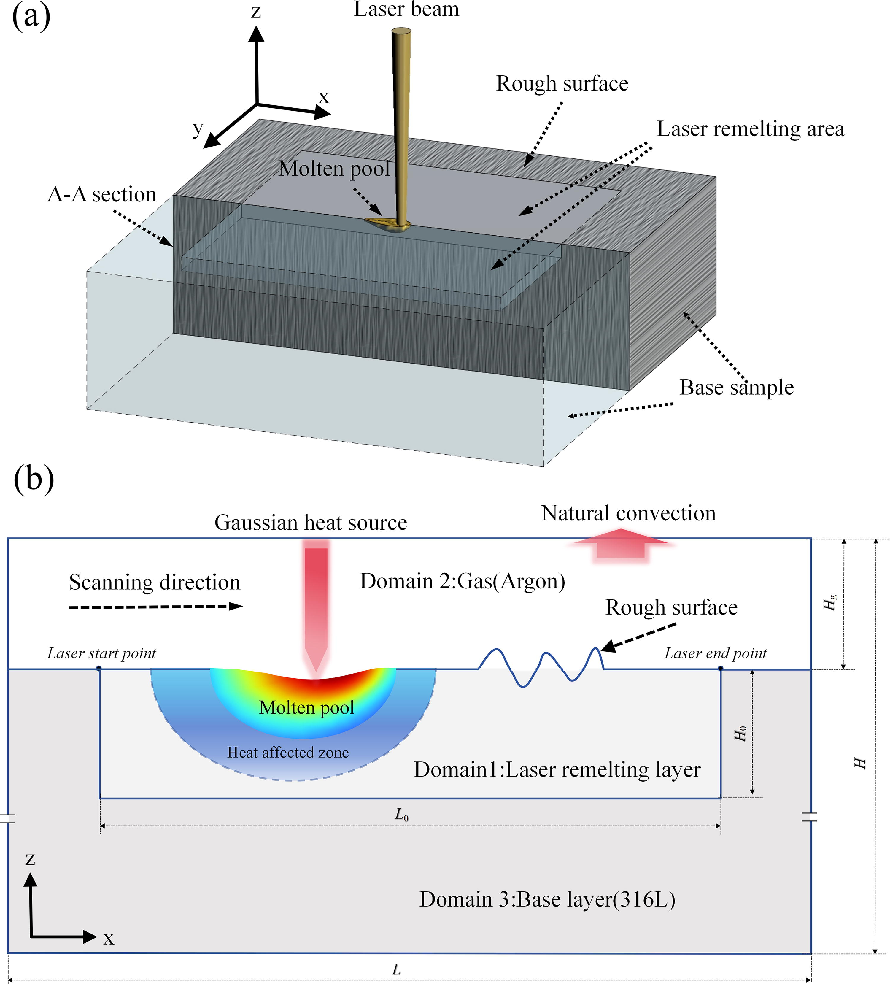
In order to analyze the evolution mechanism of rough surface during laser remelting, numerical simulation is a simple, intuitive, economical and efficient method. In this paper, using simulation software (COMSOL Multiphysics 6.2a, COMSOL Inc., Sweden), based on the Level-set method and considering the Marangoni effect, heat transfer, laminar flow and surface tension, A two-dimensional time-dependent Multiphysics-coupled finite element model of the laser-material interaction is developed [Figure 1(b)]. The basic idea of level-set method is that the interface is regarded as the zero Level set of a function (called level set function) in a higher dimensional space, and the evolution of the interface is extended to a higher dimensional space. The level set function is evolved or iterated according to the development equation it satisfies until the evolution becomes stable, then the interface shape can be obtained and the interface tracking can be carried out. Therefore, the level set method is an effective and reliable method to track the geometric shape evolution of rough surfaces. 20
As shown in Figure 1(b), in order to reduce the influence of boundary conditions on the simulation results, the size of the two-dimensional simulation region is set to be much larger than that of the molten layer, and the size of the two-dimensional simulation region is
Numerical Simulation Scheme
Thermal Property Parameters of 316L Stainless Steel
To simplify the numerical calculations, the following assumptions are made on the simulation model:
Governing equations and moving gaussian heat source
Navier-Stokes equation plays an extremely important role in fluid mechanics. It describes the conservation of momentum and mass of Newtonian fluid, and considers pressure, temperature, density and other factors. The model in this paper simulates the mass and momentum transfer of fluid based on the Navier-Stokes equation of incompressible fluid, and its equations are as follows:
24
Where
Considering the heat convection between the laser remelting layer and the argon protective layer and the heat radiation to the environment when the laser beam is scanning, the heat transfer equation can be expressed by Fourier formula as follows:
20
Where,
The laser beam in the laser remelting process is regarded as a continuous Gaussian heat source, and its equation is as follows:
25
Where,
Material phase transition
In the process of laser remelting, the temperature of the material will quickly rise to the melting point due to the action of the laser beam, and the material will change from solid phase to liquid phase. The latent heat of phase change of 316L stainless steel can be described as follows
26
:
Where
Where,
The phase transition latent heat distribution
Where,
In order to keep the unmelted material in a static flow field, the dynamic viscosity of the solid phase material is set to 1000
Surface tension and marangoni effect
The thermal gradient on the melting region and the surface tension
Where,
Recoil pressure
When the material reaches the boiling point stably and evaporation occurs, the recoil phenomenon will appear on the surface of the material. The recoil pressure
Where
Experimental procedure
Sample fabrication
A DiMetal-100 SLM forming device (Guangzhou Leijia Additive Technology Co., LTD., China) was used in the sample fabrication process, which used an IPG fiber laser with a wavelength of 1080 nm and a maximum output power of 500W. The material used to make the sample is 316L stainless steel powder. SEM (FEI Company, model Nova NanoSem 450) image of the powder material is shown in Figure 2(a), the detailed parameters of the SEM are as follows: high vacuum mode resolution: 1nm (15 KV) and 1.6 nm (1 KV); acceleration voltage: 50 V–30 kV continuously adjustable; magnification: 40×–800,000×; tilt angle: −10°−70°; sample table moving range: X = Y = 110 mm, Z = 50 mm; vacuum: sample chamber vacuum ≤ 6e-4Pa, electron gun vacuum ≤5e-7Pa.
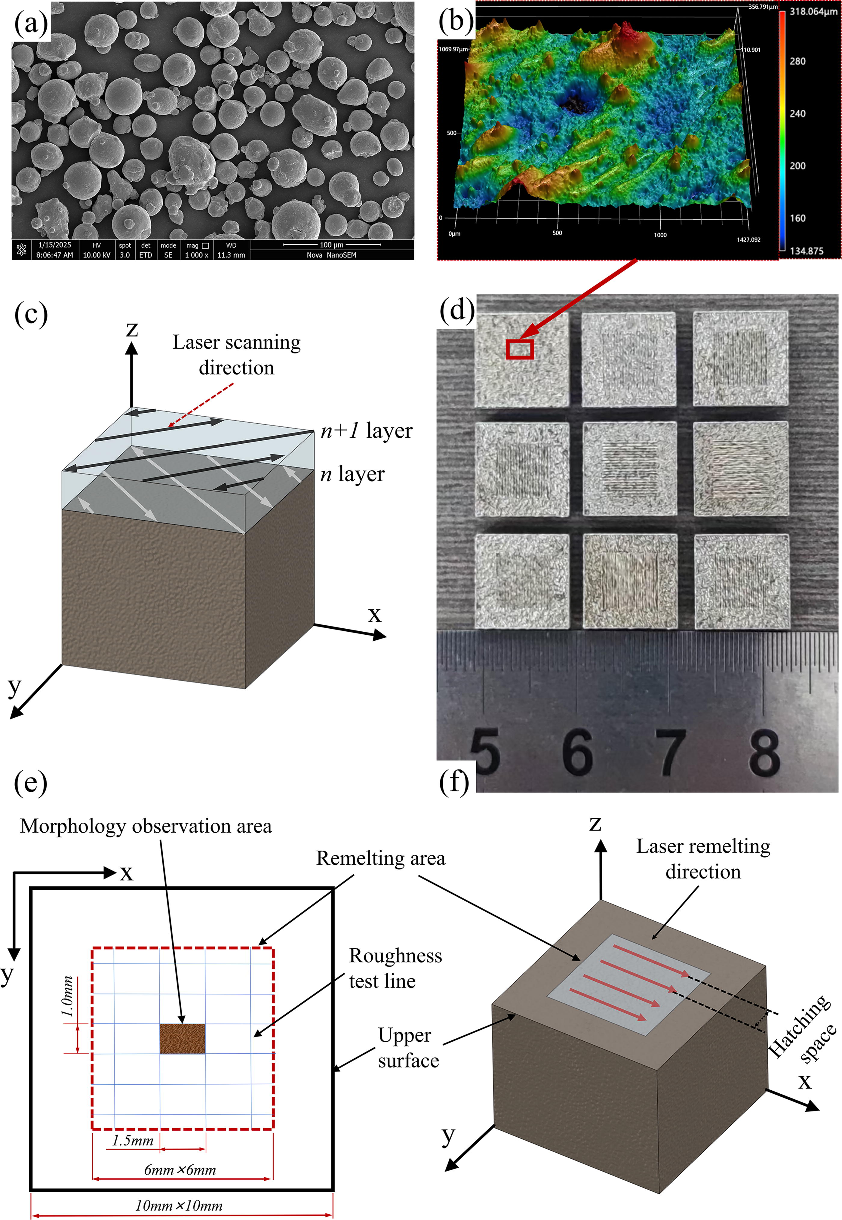
Most of the powder particles are spherical, and the particle size range is 15 − 53 μm. Before the fabrication of the sample, the platform was preheated to 400 K, and argon was turned on as a protective gas, the laser power was set to 200 W, the laser spot radius was 40 μm, the powder layer thickness was 30 μm, the scanning spacing was fixed at 40 μm, and the laser scanning speed was set at 1 m/s. In order to avoid the phenomenon of stress concentration in the rapid prototyping process, which affects the detection of sample morphology and roughness, the forming method of rotation and interleaving of adjacent layers is adopted in the forming process, 31 as shown in Figure 2(c).
A total of 9 samples were made [as shown in Figure 2(d)], and the sample size was 10 mm× 10 mm× 3 mm. After the sample was manufactured, the fixed surface of the sample was directly processed by laser remelting in the SLM equipment. The laser remelting area was a rectangular area with a size of 6 × 6 mm, as shown in Figure 2(e). The laser remelting process adopts the same direction scanning mode, and the scanning spacing is fixed as 40 μm, as shown in Figure 2(f). The laser remelting scheme is shown in Table 3. In order to facilitate analysis and comparison, only 8 of the samples were processed after laser remelting, and the remaining one sample was used for comparison of surface morphology and roughness. Figure 2(b) shows the microscopic morphology of the central region of the sample without laser remelting.
The Laser Remelting Strategy in the Experiment
Morphology observation and roughness test
After laser remelting, the sample was separated from the substrate by a wire cutting machine for surface topography observation and roughness measurement. Before testing, the sample was cleaned by ultrasonic wave to remove the residual powder and dirt on the surface. The surface roughness of Ra and Sa was measured using a roughness profiler (MMD-HPG100, Xi ‘an Weierxin Precision Instrument Co., LTD., China) and a 3D surface profiler (VK-X5000, Keenshi Co., Japan), respectively. The Ra was tested as follows: 10 test lines [as shown in Figure 2(e)] were divided in the laser remelting area on the upper surface of each sample, and their roughness values were tested respectively, and then the final Ra value was obtained by averaging the 10 measurement results. The test method of Sa is as follows: the central area of the sample is selected as the Sa measurement area, and the measurement area is a rectangular area with a size of 1.5 × 1.0 mm [Figure 2(e)]. The surface topography of the sample is photographed by a 3D surface profiler, and the Sa value is detected and obtained by the built-in system of the device.
Results and Discussion
Evolution of roughness and surface topography
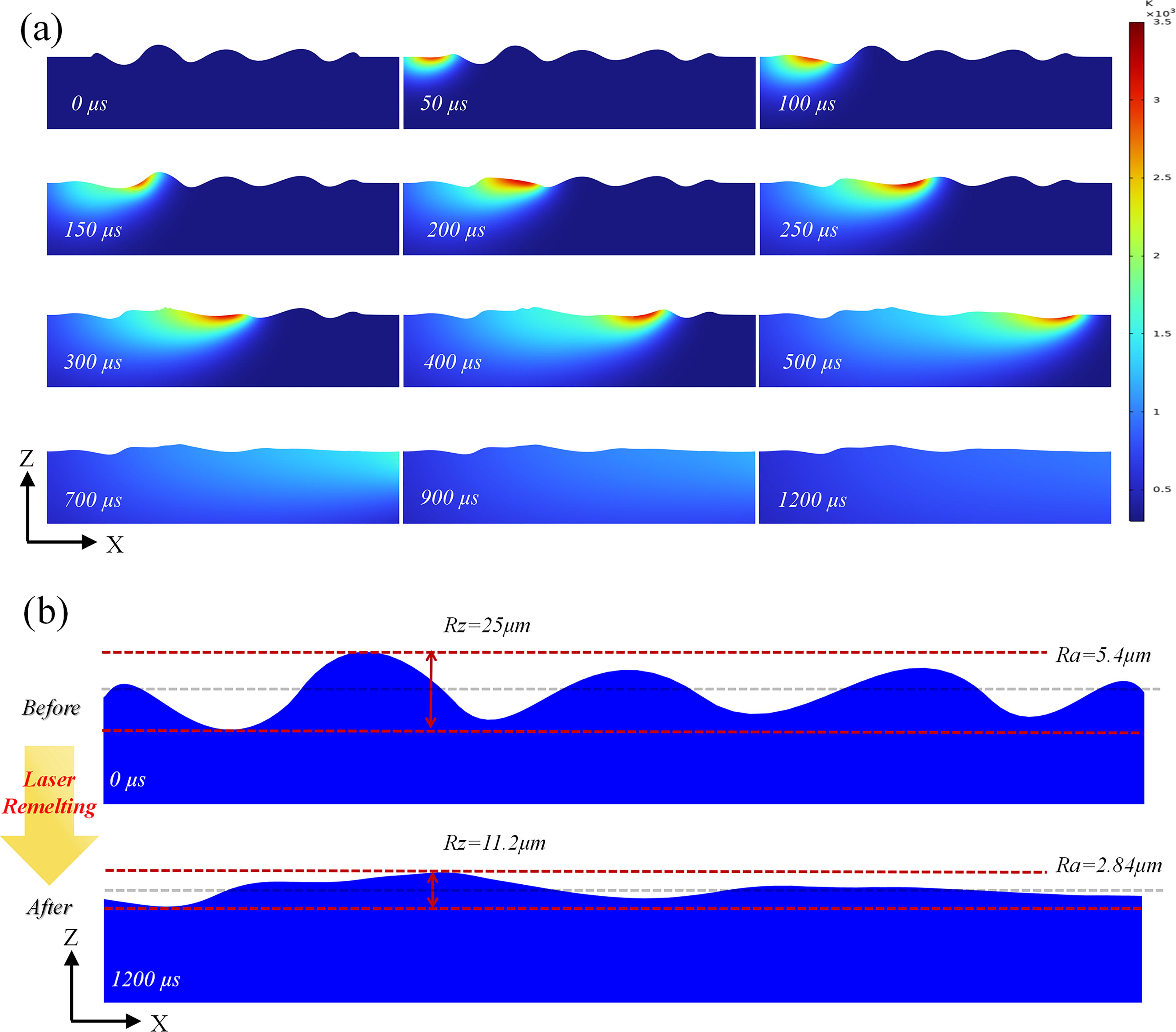
Figure 3 shows the evolution and temperature distribution of the rough surface when the laser remelting power is 300W and the scanning speed is 0.75 m/s. As can be seen from Figure 3(a), under the action of laser heat source, the temperature on the upper surface of the model gradually increases, and at t = 50 μs, a molten pool appears when the temperature rises to the melting point of 316L stainless steel material. Then, under the continuous action of the laser heat source, the molten pool gradually expanded, and after about t = 100 μs, the size of the molten pool basically reached stability, and a relatively stable temperature gradient distribution was formed around the molten pool. With the movement of the laser beam, the molten pool also moves along the positive direction of the X-axis. Under the influence of Marangoni effect, the material at the peak of the wave flows to the trough, the height difference between the peak and the trough gradually decreases, and the rough surface becomes smoother. After t = 700 μs, the temperature of the upper surface gradually decreases and the material gradually coals, but the change of the surface topography is not large due to the high cooling rate. 32 After cooling (t = 1200 μs), the free surface area is smooth and the roughness is significantly reduced. It can be seen from Figure 3(b) that after laser remelting, the peak and trough of the upper surface are significantly reduced, as well as the surface topography is smoother; therefore, the surface roughness decreases significantly. Before laser remelting, the maximum difference between peak and peak valley Rz is 25 μm, and the average roughness Ra is 5.4 μm. After laser remelting, the Rz value is reduced to 11.2 μm, Ra value is reduced to 2.84 μm, and the reduction rate of Ra is 47.4%.
Experimental results verify the effectiveness of the simulation, as shown in Figure 4, which shows the optical morphology of the central region of the sample processed after laser remelting. It can be seen from the figure that after laser remelting, the large peaks and valleys on the upper surface of the sample are significantly reduced, and the surface trajectory is more orderly and obvious. Compared with before laser remelting, the roughness Sa and Ra are all reduced to different degrees. As shown in Table 4, is the surface roughness of the sample obtained by measurement and the comparison with the simulation results. As can be seen from Table 4, the measured Sa and Ra of the initial sample are 30.9 and 12.5 μm, respectively. After laser remelting treatment, Sa and Ra are reduced to 9.8 and 5.7 μm at the lowest, and the reduction rate is 68.3% and 54.4%, respectively. Compared with the Ra reduction rate obtained by simulation analysis, it is found that the error is within 8%, and the simulation results obtained under different laser power and scanning speed show the same trend as the experimental results.

The microscopic morphology of the central region of the samples.
Surface Roughness of the Experimental Sample
Influence of laser power and scanning speed
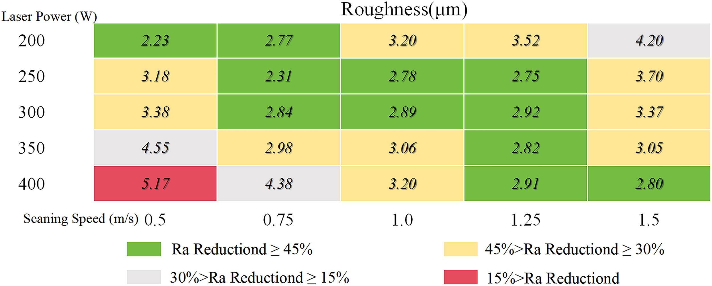
Figure 5 shows the roughness Ra values obtained by simulation analysis after remelting post-processing under different laser power and scanning speed. It can be seen from Figure 5 that mainly shows three cases: (1) When the laser power is fixed, the roughness after laser remelting gradually increases with the increase of scanning speed, as shown in Figure 6(a); (2) when the scanning speed is fixed, the roughness after laser remelting decreases gradually with the increase of laser power, as shown in Figure 6(b); and (3) the laser power and scanning speed can obtain a small roughness within a certain interval, but beyond this interval, a large roughness will be obtained, as shown in Figure 7.
Roughness Ra values obtained from numerical simulations.

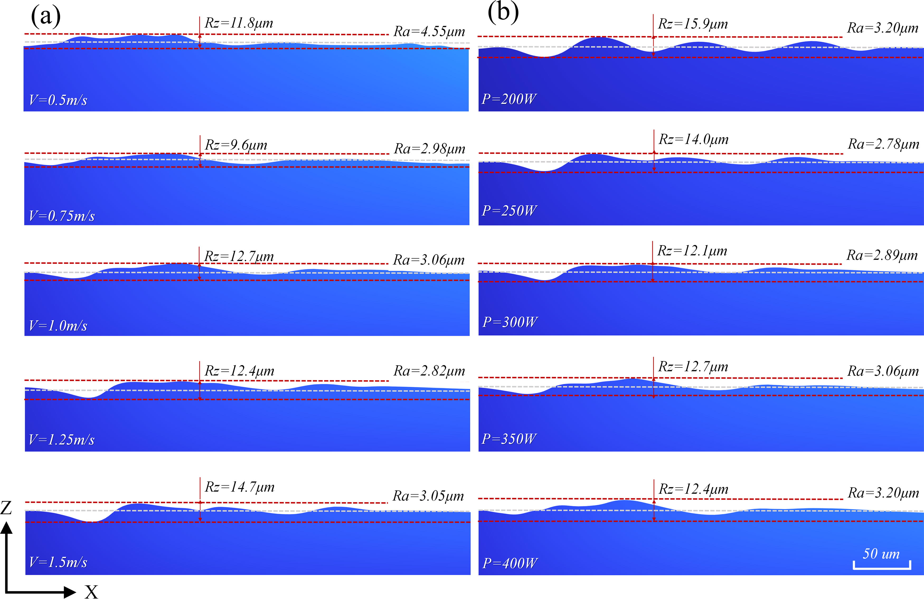
As shown in Figure 6(a), the roughness variation at different scanning speeds is shown when the laser power is fixed at 200 W. When the laser power P = 200 W and the scanning speed V = 0.5 m/s, the Rz value and Ra value obtained after laser remelting are 8.6 and 2.23 μm, respectively. When the laser scanning speed is increased to 0.75 m/s, the Rz value and Ra value obtained by laser remelting are increased to 12.9 and 2.77 μm, respectively. As the scanning speed continues to increase, due to insufficient melting of the surface material, the size of the molten pool becomes smaller, and the influence on the rough surface becomes weaker. 33 After laser remelting, the Rz value and Ra value also gradually increase, that is, the roughness gradually increases. Therefore, it can be seen that the roughness value is proportional to the laser scanning speed when the laser power is fixed. It is also shown in Figure 6(b), which shows the roughness variation under different laser powers when the scanning speed is fixed at 1.5 m/s. The Rz value is 18.8 μm and the Ra value is 4.20 μm when the scanning speed V = 1.5 m/s, as well as the laser power P = 200 W. When the laser power is increased to 250 W, the Rz value and Ra value obtained by laser remelting are decreased to 18.1 and 3.7 μm, respectively. As the laser power continues to increase, the size of the molten pool increases, and the influence on the rough surface is enhanced. After laser remelting, the Rz value and Ra value also gradually decrease, that is, the roughness gradually decreases. Therefore, it can be seen that when the scanning speed is fixed, the effect of laser remelting is increased with the increase of laser power.
As shown in Figure 7, the situation is different from the aforementioned process strategy. Figure 7(a) shows the roughness variation at different scanning speeds when the laser power is fixed at 350 W. Different from the situation shown in Figure 6(a), when the scanning speed gradually increased, the roughness Rz and Ra did not show a certain change rule. When the scanning speed increased from 0.5 to 0.75 m/s, the roughness Rz value decreased from 11.8 to 9.6 μm, and the Ra value decreased from 4.55 to 2.98 μm. When the scanning speed is gradually increased to 1.5 m/s, the roughness Ra value is basically maintained at about 3 μm, and there is no significant change. Figure 7(b) shows the roughness variation under different laser powers when the scanning speed is fixed at 1.0 m/s. Similar to the situation shown in Figure 7(a), when the laser power gradually increases, the roughness Rz and Ra do not show a certain change rule, and when the laser power increases from 350 to 400 W, the roughness Ra value increases from 3.06 to 3.2 μm. When the laser power is increased from 250 to 350 W, the Ra value of the roughness is basically maintained at about 3 μm, and there is no significant change.
In summary, different combinations of laser power and scanning speed have different effects on the post-processing effect of laser remelting of 316L stainless steel samples. When the laser power P = 200W or the scanning speed V = 1.5 m/s, the laser remelting effect will show a certain rule with the change of the scanning speed or the laser power. When the laser power P = 350 W, the change of scanning speed has little effect on the roughness in a certain range, while too low or too high scanning speed will cause large roughness. Similarly, when the scanning speed V = 1.0 m/s, the change of laser power also has little effect on the roughness within a certain range, while too low or too high laser power will cause large roughness. The specific roughness variation is shown in Figure 5.
Influence of marangoni effect
Le et al. 34 studied the influence of Marangoni effect on the formation of molten pool in the process of SLM forming stainless steel, and found that the Marangoni effect had a great influence on the geometric shape of molten pool, which would affect the formation of surface defects and the size of surface roughness. In the study presented in this paper, it is found that the Marangoni effect also has a great influence on the geometric changes of rough surfaces. In order to facilitate analysis and comparison, the first two wave peaks in the simulation model are taken as examples to analyze the evolution law of the rough surface under different laser power and scanning speed, as shown in Figure 8. In the figure, the thin black line is the boundary line between solid phase and liquid phase of the material, the black arrow represents the flow direction of the fluid in the molten pool, and the size of the arrow represents the size of the fluid flow rate.
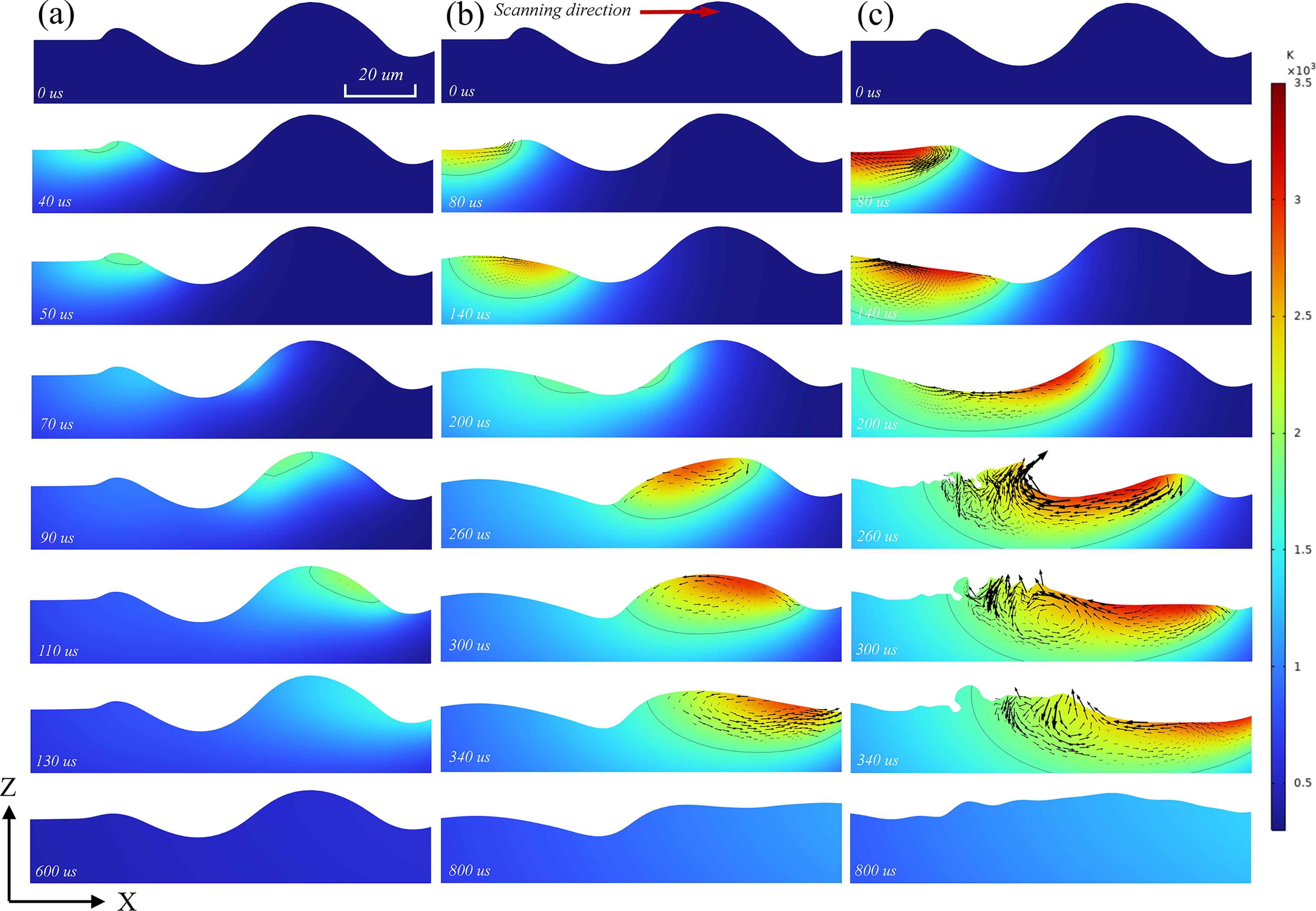
As shown in Figure 8(a), it shows the flow field variation of the molten pool when the laser power P = 200W and the scanning speed V = 1.5 m/s. When t = 40 us, the molten pool is formed at the first wave peak, but due to the fast-scanning speed, the laser action time on the surface of the material is short, the temperature of the material is not high, and the size of the molten pool is small, and the fluid flow rate in the molten pool is small. At t = 110 us, the fluid flow rate in the molten pool reaches the maximum, but it is only 0.13 m/s. In this case, because there is no obvious fluid flow in the molten pool during the scanning process, it is difficult to eliminate the wave peaks and troupes. The rough surface morphology after laser remelting has little difference from the initial state, and the roughness improvement is not obvious.
As shown in Figure 8(b), it shows the flow field variation of the molten pool when the laser power P = 200 W and the scanning speed V = 0.5 m/s. Similarly, under the action of the laser beam, a molten pool is formed on the upper surface of the model at t = 40 us and moves to the first wave peak at t = 80 us. Because the scanning speed is slow, the laser beam acts on the surface material for a long time, and the material temperature is high, so the size of the molten pool is obviously larger than that shown in Figure 8(a), and the fluid flow in the molten pool is also relatively obvious. Due to the Marangoni effect, the fluid in the molten pool moves toward the tail region of the molten pool. 35 Until t = 260 us, when the molten pool passes through the second wave peak, the peak material can flow to the trough, and the peak gradually decreases. At t = 300 us, under the effect of Marangoni effect, eddy current is formed at the top of the peak, meanwhile the fluid has a tendency to move to the trough. At t = 340 us, the molten pool fluid flows from the peak to the trough under the action of gravity, and the peak is further weakened. At this time, the fluid flow velocity also reaches a maximum of 1.2 m/s. After t = 400 us, the material gradually coals, and due to the fast-cooling rate, the fluid flow rate approaches zero after cooling of the molten pool, and the surface morphology does not change much. At the final t = 800 us, it can be seen that the peaks and troughs become significantly smaller, and the rough surface is significantly improved.
As shown in Figure 8(c), the flow field of the molten pool changes when the laser power P = 350 W and the scanning speed V = 0.5 m/s. As shown in Figure 8(b), a molten pool is formed on the upper surface of the model at t = 40 us and moves to the first wave peak at t = 80 us. The difference is that due to the higher laser power, the size of the molten pool is significantly larger and the fluid flow rate in the molten pool is faster. At t = 200 us, the molten pool moves to the second wave peak. At this time, the molten material of the first wave peak and the molten material of the second wave peak move to the trough under the force of gravity, so that the trough is further filled. At t = 260 us, the fluid velocity in the molten pool reaches a maximum of 2.4 m/s. Due to the high fluid velocity, turbulent flow is formed at the tail of the molten pool, which is basically stable until t = 340 us, which leads to the formation of a new, smaller rough surface. After cooling of the molten pool, at t = 800 us, it can be seen that the trough has been completely filled, but due to the disorder of the fluid flow direction, new smaller peaks and troughs are formed on the rough surface, 35 and the roughness is not as good as that shown in Figure 8(b).
Conclusion
In this paper, a multi-physics coupled finite element model based on the level set method is established, and the evolution of the rough surface during laser remelting is studied in detail by numerical simulation. Through numerical simulation, it is found that in the process of laser remelting 316L stainless steel, on the one hand, the molten pool fluid will move to the tail of the molten pool under the action of Marangoni effect, on the other hand, the molten pool fluid will flow from peak to trough under the action of gravity. It is this mass transfer movement that weakens the peak and trough of the rough surface and improves the surface roughness. In addition, the effectiveness of the numerical simulation is verified by experiments, and the maximum error between the experimental results and the simulation results does not exceed 8%. The main conclusions of this study can be summarized as follows:
Laser remelting post-processing is one of the effective ways to improve the surface quality of SLM formed parts, and the process does not need additional equipment, and can be carried out directly after SLM forming, which greatly improves the process efficiency; The main reason that laser remelting can reduce the roughness is that the difference between the peak and the trough of the wave is reduced by the fluid flow after the surface material is melted, and the flow of the molten material is mainly affected by the Marangoni effect and gravity; The laser power and scanning speed has a certain impact on the effect of laser remelting, and appropriate laser power and scanning speed can achieve better laser remelting effect. In the numerical simulation of this paper, when the laser power P = 200 W and the scanning speed V = 0.5 m/s, the laser remelting effect is the best, and the reduction rate of roughness Ra reaches 58.7%。 In the future research work, the multi-physical field finite element analysis model will continue to be developed to consider more influencing factors, such as scanning path and scanning interval to simulate and analyze the influence of different process strategies on the laser remelting effect.
Footnotes
Authors’ Contributions
Z.L.: Conceptualization, methodology, formal analysis, investigation, and writing—original draft. Y.G.Z.: Funding acquisition, writing—review and editing, and project administration. Y.P.M.: Methodology, formal analysis and investigation. J.Y.D.: Formal analysis, investigation. F.W.: Experiment and test.
Author Disclosure Statement
No competing financial interests exist.
Funding Information
This research was funded by the National Natural Science Foundation of China under Grant No. 62063010;Science and Technology project of Education Department of Jiangxi Province, China, Grant No. GJJ2407704.