
Abstract
In the frame of the EXPOSE-E mission on the Columbus external payload facility EuTEF on board the International Space Station, passive thermoluminescence dosimeters were applied to measure the radiation exposure of biological samples. The detectors were located either as stacks next to biological specimens to determine the depth dose distribution or beneath the sample carriers to determine the dose levels for maximum shielding. The maximum mission dose measured in the upper layer of the depth dose part of the experiment amounted to 238±10 mGy, which relates to an average dose rate of 408±16 μGy/d. In these stacks of about 8 mm height, the dose decreased by 5–12% with depth. The maximum dose measured beneath the sample carriers was 215±16 mGy, which amounts to an average dose rate of 368±27 μGy/d. These values are close to those assessed for the interior of the Columbus module and demonstrate the high shielding of the biological experiments within the EXPOSE-E facility. Besides the shielding by the EXPOSE-E hardware itself, additional shielding was experienced by the external structures adjacent to EXPOSE-E, such as EuTEF and Columbus. This led to a dose gradient over the entire exposure area, from 215±16 mGy for the lowest to 121±6 mGy for maximum shielding. Hence, the doses perceived by the biological samples inside EXPOSE-E varied by 70% (from lowest to highest dose). As a consequence of the high shielding, the biological samples were predominantly exposed to galactic cosmic heavy ions, while electrons and a significant fraction of protons of the radiation belts and solar wind did not reach the samples. Key Words: Space radiation—Dosimetry—Passive radiation detectors—Thermoluminescence—EXPOSE-E. Astrobiology 12, 387–392.
1. Introduction
The European Space Agency astrobiology facility EXPOSE-E, which was attached to the external European Technology Exposure Facility (EuTEF) platform of the International Space Station (ISS) for 1.5 years (Fig. 1), housed a variety of organisms (from microorganisms to plant seeds) and organic chemical compounds. The samples were exposed to selected space conditions (vacuum, solar UV, cosmic rays, and varying temperatures), and their reactions were analyzed after retrieval. EXPOSE-E was launched by STS-122 on 7 February 2008 and returned to Earth by STS-128 on 12 September 2009.
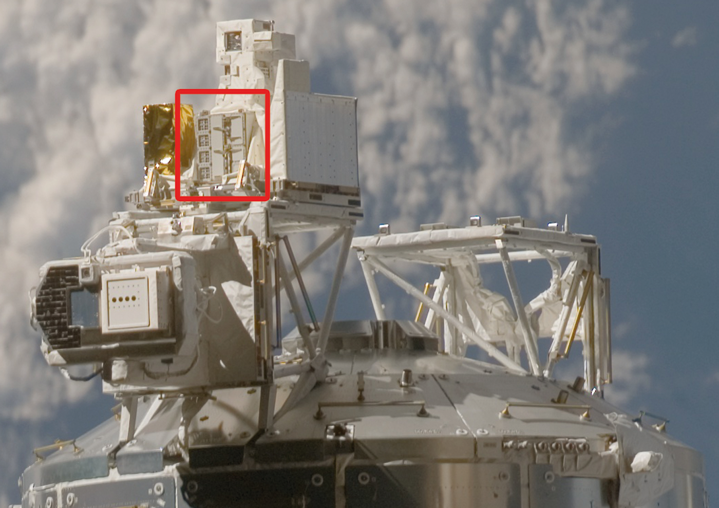
EXPOSE-E experiment carrier (framed) attached to the EuTEF external platform of the European Columbus laboratory. Color images available online at
The absorbed dose received by the biological samples contained in the EXPOSE-E experiment carrier was measured within the Dose Distribution Inside the ISS (DOSIS) experiment. As a follow-up of the Dosimetric Mapping (DOSMAP) experiment (Reitz et al., 2005), DOSIS is a comprehensive and overarching international dosimetry program dedicated to determining the nature and mapping the distribution of the radiation field inside and outside the European Columbus laboratory with active and passive radiation detectors. Passive thermoluminescence detectors (TLDs) have been applied for radiation measurements on board various space stations and space shuttle missions since the beginning of the space age (Berger, 2008; Reitz et al., 2005, 2009; Hajek et al., 2008). Their small size of a few cubic millimeters and low mass (around 20 mg) allow affixing them close to the samples of interest. During the EXPOSE-E mission, TLDs were accommodated at different sites in close vicinity to the biological specimens. The data acquired within the experiment provided reference doses for the ADAPT, PROTECT, and LIFE missions (Rabbow et al., 2009, 2012; Horneck et al., 2012).
2. Material and Methods
2.1. Radiation detectors
Thermoluminescence detectors made of 7LiF with Mg and Ti dopants, which were provided by Thermo Fisher Scientific, Inc. (former Harshaw Chemical, Co.), Solon, Ohio, USA, under the trade name TLD-700, and TLD Poland, Krakow, Poland, under the trade name MTS-7, were used as passive radiation dosimeters. The energy deposited by ionizing radiation in the TLDs is stored at defect centers in the crystal lattice. During readout in the laboratory, the stored energy is released as light upon heating. When the light intensity is plotted over temperature, which yields the so-called glow curve, the amplitude or region of interest (ROI) of specific peaks is proportional to the absorbed dose and thus enables TLD utilization in radiation dosimetry upon calibration in gamma-ray fields. The experimental protocols, used by the different research groups for TLD annealing and readout, are summarized in Table 1. Throughout the present paper, all doses are given in terms of absorbed dose in water.
ATI and DLR applied TLD-700 detectors manufactured by Thermo (USA) with a dimension of 3.2×3.2×0.9 mm.
IFJ and SCK·CEN applied MTS-7 detectors manufactured by TLD Poland with a diameter of 5 mm and a thickness of 0.9 mm.
2.2. Spaceflight experiment
It was expected that the doses would vary over the area of EXPOSE-E according to the variation in shielding by the different structural materials in the vicinity of the facility (Fig. 1).
To obtain the actual doses received by the biological samples of EXPOSE-E to the best extent possible, the radiation detectors were placed close to the samples. TLDs were located in each compartment of the biological experiments ADAPT, PROTECT, and LIFE at two different sites to provide information on the following radiation parameters: • Mission dose: TLDs of the types TLD-700 (ATI and DLR) and MTS-7 (IFJ and SCK·CEN) enclosed in acrylic glass holders with a dimension of 28×28×8.5 mm were placed beneath the biological sample carriers in tray 1 and tray 2 of the EXPOSE-E facility (Fig. 2 left). • Depth dose distribution: Small holes of 5 mm diameter and 8 mm depth were drilled in the sample carriers between the biological samples of the ADAPT, PROTECT, and LIFE experiments in tray 1 and tray 2 of the EXPOSE-E facility to house the so-called “depth dose samples” (Fig. 2 right). Within these holes, stacks of eight TLDs (TLD-700 and MTS-7) were used to measure the dose gradient from top to bottom.
After return of EXPOSE-E to ground, the TLDs were extracted from the facility at DLR, Cologne, Germany, and distributed to the project partners (ATI, Vienna, Austria; IFJ, Krakow, Poland; and SCK·CEN, Mol, Belgium) for processing and evaluation. TLD readout and data acquisition followed the protocols outlined in Table 1. Due to the fact that TLDs are integrating devices, only the total absorbed dose accumulated over the entire duration of the EXPOSE-E mission was measured.
3. Results
To study the absorbed dose from ionizing radiation during the EXPOSE-E experiment, TLDs of the types 7LiF:Mg, Ti were contained in acrylic glass holders below the biological sample carriers (see left part of Fig. 2) or in dedicated drilled holes next to the biological samples (see right part of Fig. 2). The mission-integrated absorbed dose beneath the biological sample carriers is shown for each position within trays 1 and 2 of the EXPOSE-E facility in Fig. 3. The given uncertainties correspond to one standard deviation of the mean. Position #1 is located closest to the EuTEF platform and the Columbus module (Figs. 1 and 3). In both trays, position #1 gave the lowest dose values: 129±13 mGy (tray 1) and 121±7 mGy (tray 2), which indicates the shielding by the adjacent structures. There was an increase in dose from position #1 to position #8, reaching at position #8 a dose of 208±8 mGy for tray 1 and 215±16 mGy for tray 2. In both trays, the dose increased by about 70% when moving from position #1 to position #8. Position #8 was pointing more toward space and obviously provided the lowest shielding (Figs. 1 and 3).
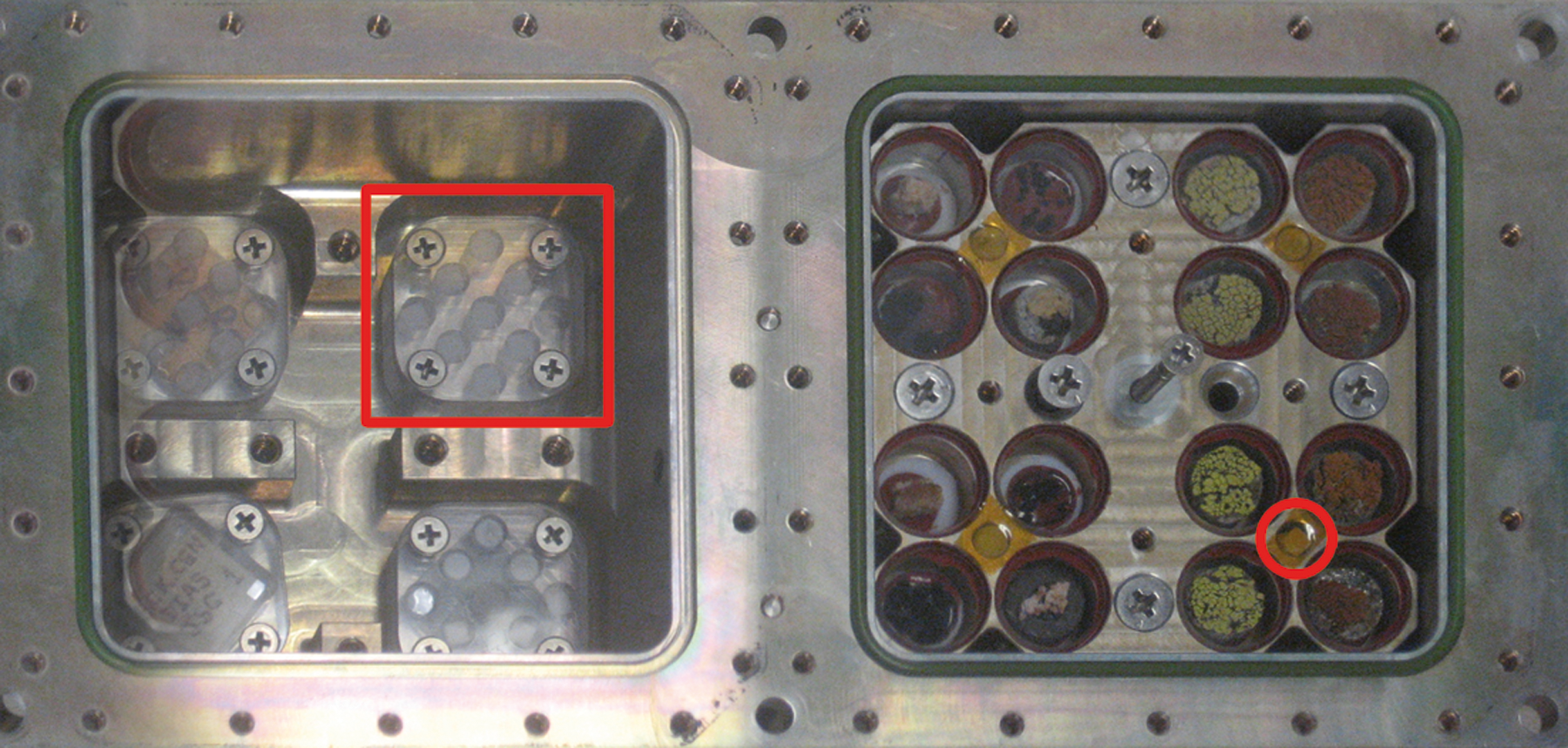
Left: TLDs in acryl glass holders (framed) installed beneath the ADAPT-1 dark samples in Tray-1 of the EXPOSE-E facility. Right: DOSIS “depth dose samples.” The location of a TLD stack is indicated exemplarily by a circle. Within one of these holes eight TLDs are stacked to measure the depth dose distribution. Color images available online at
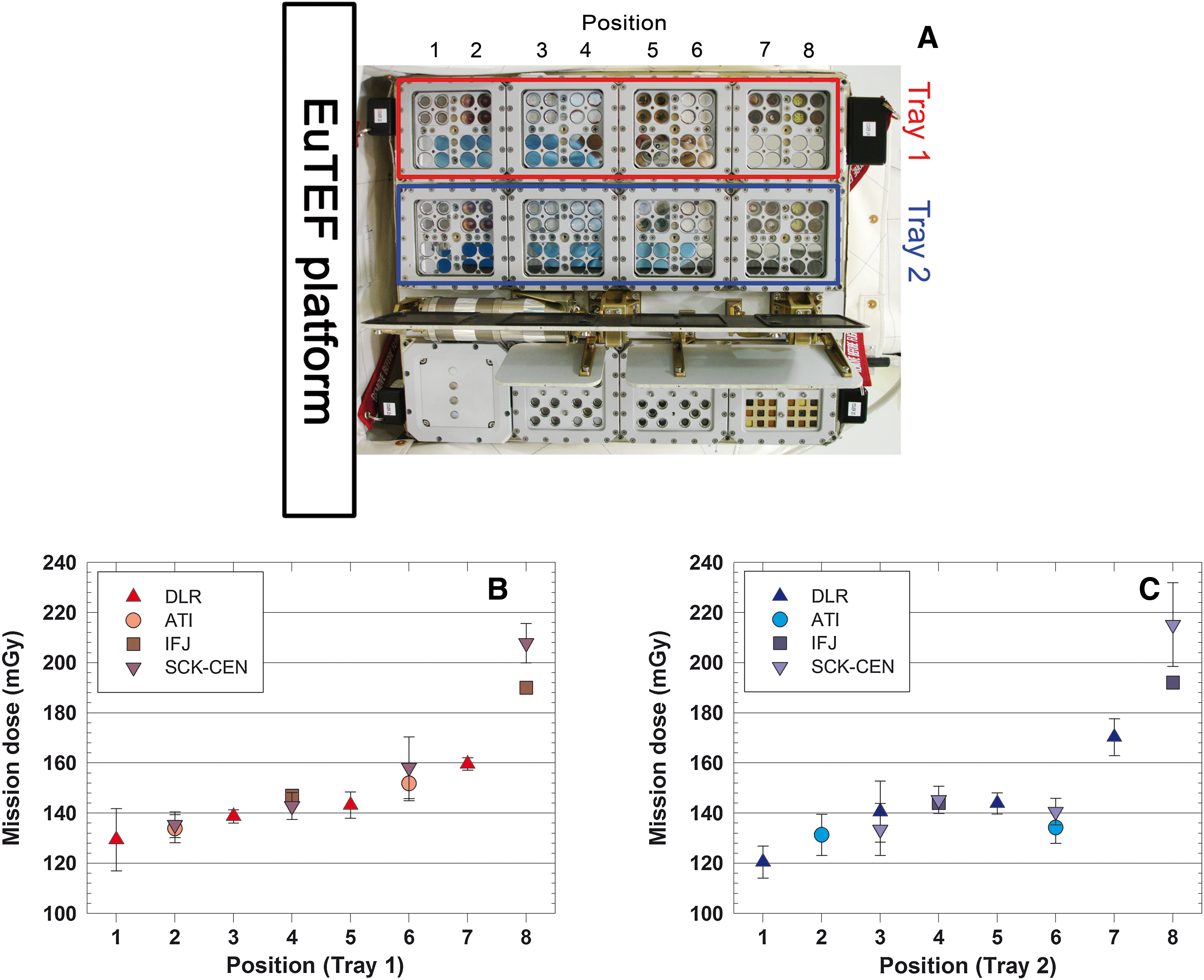
Total mission dose determined by TLDs beneath the biological sample carriers in trays 1 and 2 of the EXPOSE-E facility in dependence on the location of the sample. (
The results from the DOSIS depth dose experiment at three sample locations within tray 2 of the EXPOSE-E facility are illustrated in Fig. 4 as mission-integrated absorbed doses for the entire duration of the experiment. Uncertainties of evaluated doses were estimated from repeated calibrations of the individual TLDs. For each site, they show a slight decrease of dose with depth, for example, from 144±6 mGy to 137±5 mGy at position #2 and from 238±10 mGy to 211±8 mGy at position #8. Similar to the data of the total mission dose (Fig. 3), the highest dose was encountered at site #8 with the lowest shielding from the EuTEF platform, while the lowest dose was seen at the best-shielded position #2. In addition, position #8 showed the steepest gradient and position #2 the flattest gradient of the depth dose decrease.
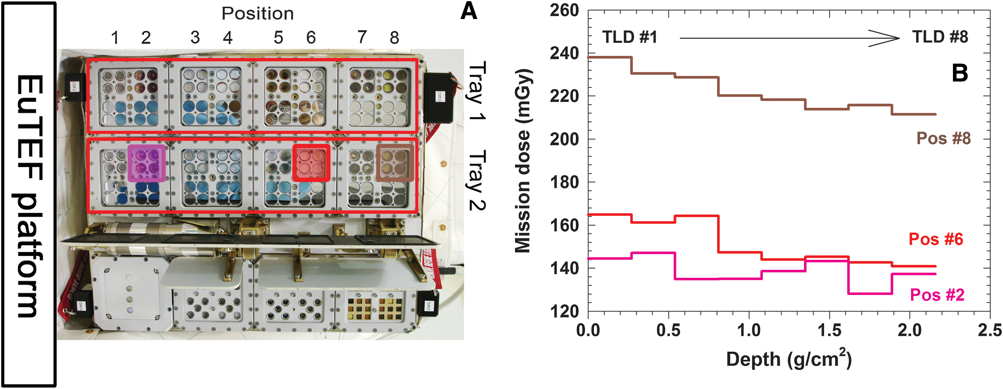
Depth dose distribution measured with a stack of eight 7LiF:Mg, Ti TLDs at sites #2, #6 (data: DLR), and #8 (data: IFJ) in tray 2 of the EXPOSE-E facility. (
4. Discussion
In EXPOSE-E, the biological samples were accommodated beneath an optical filtering system that consisted of either a 0.8 cm thick MgF2 window (tray 1) or a 0.8 cm thick quartz window (tray 2), which caused shielding of 2.52 g/cm2 or 2.20 g/cm2, respectively. A best approximation of their radiation exposures is obtained from the absorbed doses, determined in the upper layers of the depth dose experiment (Fig. 4). The maximum dose of 238±10 mGy measured at position #8 corresponds to a dose rate of 408±16 μGy/d, while the maximum dose of 144±6 mGy encountered at position #2 yields a dose rate of 246±10 μGy/d.
Because the biological samples were housed in two aluminum carriers put on top of each other, a further decrease in dose occurred toward the bottom layer, beneath which the TLDs were placed (compare Fig. 3 with Fig. 4). In addition, shielding by the EuTEF platform and the Columbus module caused a gradient of dose; it increased by about 70% from the highly shielded position #1 to the less shielded position #8 (Fig. 3). From the mission-integrated doses, the average dose rate was calculated to range from 207±12 μGy/d to 368±27 μGy/d. These numbers are very close to the dose rates measured inside the Columbus laboratory and other segments of the ISS, which have an average shielding between 5 and 10 g/cm2 (Hajek et al., 2008; Reitz et al., 2005, 2009; Berger, 2008). This similarity in dose rates inside EXPOSE-E and inside the Columbus module reflects the high amount of shielding of the biological samples located within the EXPOSE-E facility.
Depth dose measurements at the surface of the human phantom Matroshka, which was attached to the outside of the ISS and exposed to open space from January 2004 to August 2005 (Reitz et al., 2009), showed a steep decrease in the absorbed dose within the first 2 g/cm2 of shielding (Fig. 5). Behind a shielding of around 2 g/cm2 or more the radiation dose is mainly attributed to galactic cosmic rays, while electrons and a significant fraction of protons of the solar wind and the radiation belts are already stopped in the outer layers. As a consequence, the biological specimens of EXPOSE-E that were located behind a shielding of 2.2 g/cm2 or more were mainly kept clear from the electrons and the majority of protons of the radiation field in space, and heavy ions predominantly reached the samples.
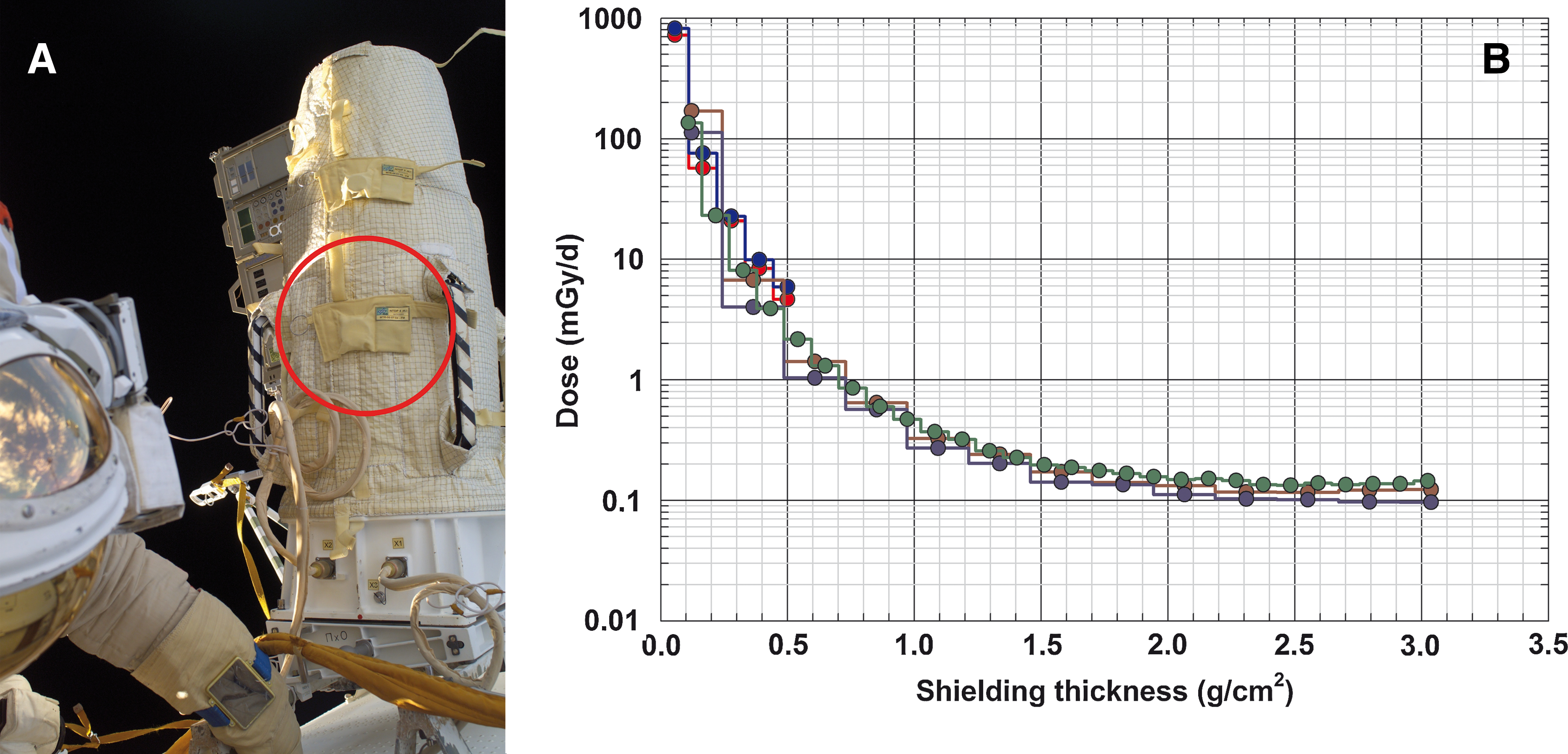
Decrease of the absorbed dose rate with shielding (
5. Outlook
Reliable assessment of characteristic radiation field parameters in low-Earth orbit, such as the absorbed dose from ionizing radiation, is a crucial prerequisite for the plausible modeling of potential radiation effects for various biological endpoints. The DOSIS experiment measured the absorbed dose within the EXPOSE-E facility for the total mission duration, which resulted in doses between 121±6 and 238±10 mGy. Investigations in the frame of the EXPOSE facility class will be continued with the EXPOSE-R and the upcoming EXPOSE-R2 missions.
Footnotes
Acknowledgments
The Austrian participation in this experiment was supported by the Austrian Space Applications Programme (ASAP) of the Federal Ministry for Transport, Innovation and Technology under contract no. 819643. The Polish contribution to this work was supported by the Ministry of Science and Higher Education, grants No. DWM/N118/ESA/2008 and N N505 261 535.
Author Disclosure Statement
No competing financial interests exist.
Abbreviations
ATI, Institute of Atomic and Subatomic Physics; DLR, German Aerospace Center; DOSIS, Dose Distribution Inside the ISS; EuTEF, European Technology Exposure Facility; IFJ, Institute of Nuclear Physics; ISS, International Space Station; ROI, region of interest; SCK·CEN, Belgian Nuclear Research Centre; TLD, thermoluminescence detector.