
Abstract
The Mars Icebreaker Life mission will search for subsurface life on Mars. It consists of three payload elements: a drill to retrieve soil samples from approximately 1 m below the surface, a robotic sample handling system to deliver the sample from the drill to the instruments, and the instruments themselves. This paper will discuss the robotic sample handling system.
Collecting samples from ice-rich soils on Mars in search of life presents two challenges: protection of that icy soil—considered a “special region” with respect to planetary protection—from contamination from Earth, and delivery of the icy, sticky soil to spacecraft instruments. We present a sampling device that meets these challenges. We built a prototype system and tested it at martian pressure, drilling into ice-cemented soil, collecting cuttings, and transferring them to the inlet port of the SOLID2 life-detection instrument. The tests successfully demonstrated that the Icebreaker drill, sample handling system, and life-detection instrument can collectively operate in these conditions and produce science data that can be delivered via telemetry—from dirt to data. Our results also demonstrate the feasibility of using an air gap to prevent forward contamination. We define a set of six analog soils for testing over a range of soil cohesion, from loose sand to basalt soil, with angles of repose of 27° and 39°, respectively. Particle size is a key determinant of jamming of mechanical parts by soil particles. Jamming occurs when the clearance between moving parts is equal in size to the most common particle size or equal to three of these particles together. Three particles acting together tend to form bridges and lead to clogging. Our experiments show that rotary-hammer action of the Icebreaker drill influences the particle size, typically reducing particle size by ∼100 μm. Key Words: Mars—Analogue—Life-detection instruments—Planetary protection—Spacecraft experiments. Astrobiology 13, 354–369.
1. Introduction
T
Future robotic missions to Mars with the capability to gather samples at greater depths are now under consideration and being developed. The Mars Icebreaker Life mission, a Discovery-class mission to the polar region of Mars, is an example of such a mission. The primary sampling goal for Icebreaker is to drill and sample to 1 m in the ice-cemented ground near the Phoenix site. There, biomarkers and organics may be preserved in that they are shielded from harmful surface radiation and oxidants. A specially designed auger has been developed for this mission (Glass et al., 2011; Zacny et al., 2013), and the associated science instruments have been identified (McKay et al., 2013). The 1 m drill itself or an end-to-end pneumatic system may be used to deliver samples to the science instruments (Zacny et al., 2012). However, the instruments require that small measured amounts, in some cases 1 mL, are delivered to intake ports smaller than a matchbox. A precision sample delivery system for future Mars missions is explored here.
The Icebreaker mission will search for life on Mars with a new class of instrumentation—immunoassay detection of biomarkers. Immunoassays detect a range of biomarkers, from complex molecules that would constitute persuasive evidence of life down to simple organics that may be biological or nonbiological in origin.
The Mars Icebreaker Life mission focuses on the following science goals (McKay et al., 2013): (1) Search for specific biomolecules that would be conclusive evidence of life. (2) Search for organic molecules in the ground ice. (3) Determine the processes of ground ice formation and the role of liquid water. (4) Understand the mechanical properties of the Mars polar ice-cemented soil. (5) Assess the recent habitability of the environment with respect to required elements to support life, energy sources, and possible toxic elements. (6) Compare the elemental composition of the northern plains with midlatitude sites.
Icebreaker capitalizes on the Phoenix mission's discovery of a habitable environment by returning to the ice-rich regions of the martian arctic to search for life (Smith et al., 2009; Stoker et al., 2010). The mission also takes advantage of the Phoenix heritage and future heritage of the Mars InSight mission by employing the same lander.
Sample handling and delivery are technical challenges for robotic planetary missions. Designs must take into account the physical and chemical properties of the sampled materials, the requirements of different payload instruments, and planetary protection constraints to avoid forward, backward, and cross contamination. The designs must allow remote operation by using automated sequences. Because of light-speed delays, teleoperation on Mars is not feasible; hence drilling placement and control, both nominal and in fault modes, must be automated (Glass et al., 2011). Icebreaker's two main challenges in sample handling are (1) meeting planetary protection requirements and (2) retrieving icy, clumpy, subsurface samples.
The sample handling system must feed cuttings from the drill to instruments on the lander deck in a manner consistent with planetary protection requirements.
Icebreaker will drill into ice-rich subsurface material, which is defined as a “special region” by COSPAR (Beaty et al., 2006; Kminek et al., 2010), so exceptional planetary protection requirements apply. Special regions are locations on Mars in which the growth of contamination microbes from Earth cannot be ruled out at this time (Beaty et al., 2006; Kminek et al., 2010). Because the Icebreaker drill will contact the subsurface special region of ice, according to Planetary Protection Category IVc it must be subjected to Viking-like dry heat microbial reduction and transported in a biobarrier—as was the Phoenix arm (Salinas et al., 2007; Bonitz et al., 2008).
The second challenge for the Icebreaker sample handling system is the prospect of sticky soils. During the Phoenix mission, nearly one-third of attempts to deliver samples were unsuccessful due to the cohesive nature of local soils (Arvidson et al., 2009). The Viking 2 lander also experienced a clogged instrument input port and strong cohesive clods (Moore and Jakosky, 1989) and observed ice on the martian surface (Svitek and Murray, 1990). This cohesive soil consistency, believed to be due to perchlorate salt and water ice that form a eutectic slush (Arvidson et al., 2009), may be present in many areas on Mars and is known to be present at the Phoenix site—the nominal target site for the Icebreaker Life mission.
In this paper, we present a conceptual design that meets both the planetary protection and sticky soil challenges. Please note that although cohesive soil could be defined as soil that clings to itself and sticky soil could be defined as soil that clings to other objects, we use these terms interchangeably. We report prototype testing completed in Mars-like environmental conditions for a sampling device that collected cuttings produced by a drill and delivered them to science instruments. We believe our observations and results may apply to any future method of retrieving icy soil on Mars.
The first section describes the challenges of planetary protection and sticky soil in more detail. We then describe the current sample delivery prototype and its performance in the range of tests both outside and inside a Mars simulation chamber. A useful product of this research is the analysis of a set of Earth soils spanning a range of cohesiveness and textural features, and their comparison with Phoenix soils. Some generally applicable design principles related to jamming of sample systems by soil grains derived from this comparison are presented in the final section.
2. Design Challenges: Planetary Protection and Sticky Soils
The main design goal of the sample handling system is to develop a system that can successfully deliver sticky dirt samples produced by the drill to the science instruments while ensuring that planetary protection requirements are met. For the Phoenix mission, the arm was the only spacecraft element that entered the special region, so it was dry heat processed and enclosed in a biobarrier on the lander deck to prevent it from contacting the other parts of the lander or receiving any cross contamination (Salinas et al., 2007; Bonitz et al., 2008). The nominal operating mode of the arm was to scoop up martian soil and let it drop, by gravity alone, onto the screens above the sampling ports of the science instruments.
We have assumed that the Icebreaker drill will be similarly processed by dry heat to reduce microbial contamination and encased in a biobarrier during the launch and cruise phases of the mission (Paulsen et al., 2011; McKay et al., 2013; Zacny et al., 2013). The barrier keeps the drill from accumulating contaminants while on Earth and from other parts of the spacecraft during cruise and after landing. The drill will break out of its biobarrier just before use (see Fig. 1). This design meets COSPAR “special region” regulations that (1) all elements that enter the special region and contact the subsurface ice be subjected to dry heat microbial reduction and (2) subsystems not subjected to dry heat microbial reduction must not come in contact with the hardware that has been subjected to dry heat microbial reduction.
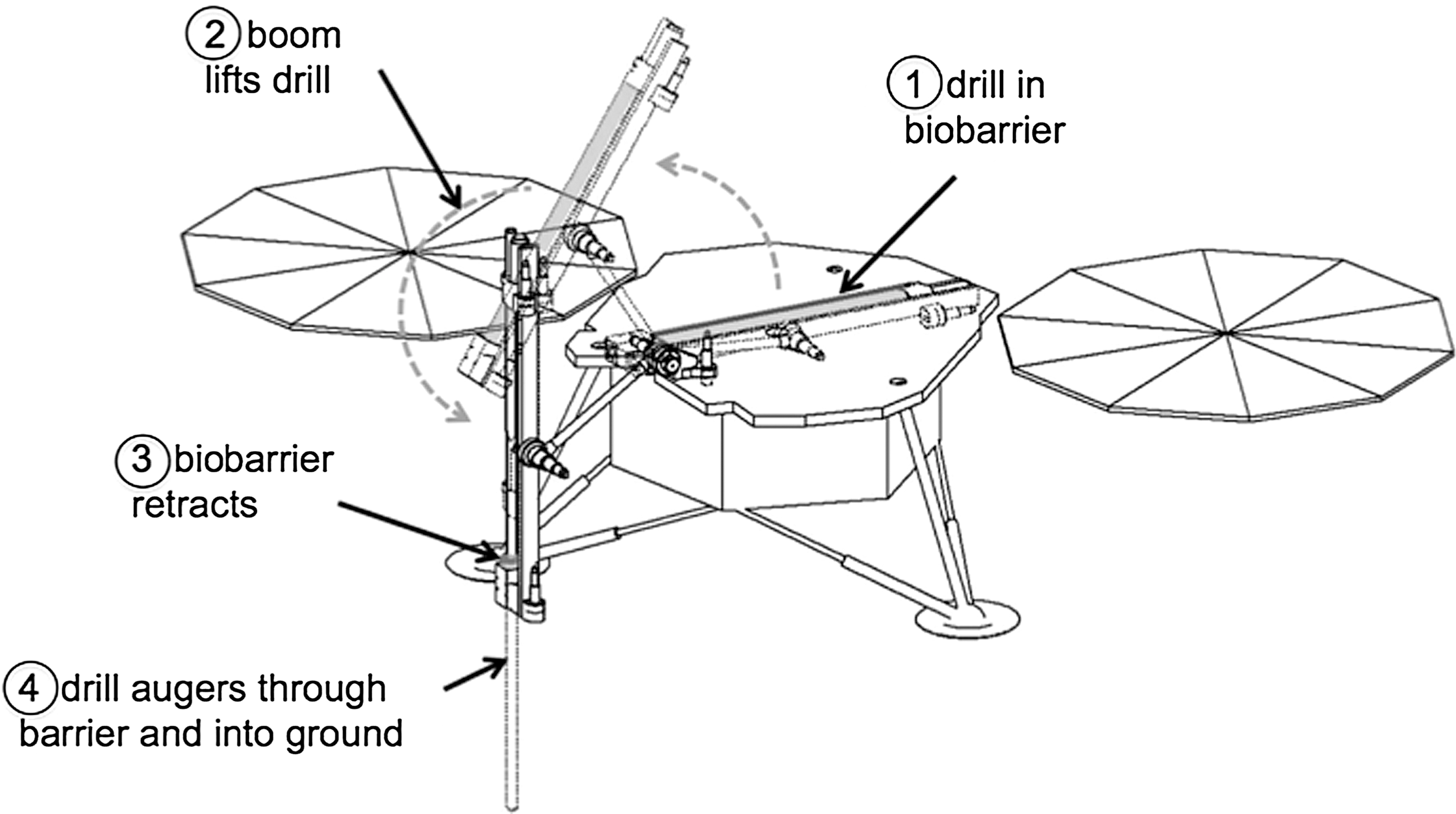
The lander with the drill in its biobarrier moving from the stowed to deployed configuration.
After the biobarrier is opened, the drill will auger into the subsurface and bring cuttings to the surface. A sample handling system will then collect these cuttings and transfer them to scientific instruments on the lander's deck. The sampling device must not touch the clean drill when retrieving soil samples, so as not to introduce contamination from the spacecraft to the subsurface special region. Therefore, an “air gap” between the device and the drill must be maintained (see Fig. 2). This air gap eliminates the need for the sample handling device, the instruments on deck, and the deck itself to follow Category IVc requirements because they are isolated from the drill and do not enter the special region. Samples can be transferred from the drill to the sampling device by passive (gravity feed) or active (brush or compressed air) mechanisms. It is important to note that this design is based on our interpretation of the Category IVc requirements and how they were implemented into the Phoenix mission. Final decisions on the planetary protection requirements will be reached once the mission is selected for Phase A studies. A formal agreement with NASA's Planetary Protection Officer based on the operative COSPAR regulations will be made during that time.
(
A second challenge to the Icebreaker Life sample handling system is the prospect that the soil will be sticky and will not easily come loose from the sampling system. This was observed during the Phoenix mission (Arvidson et al., 2009) and posed a major obstacle to sampling. Soil not only stuck within the sample scoop, but when placed over the inlet screen of the Thermal Evolved Gas Analyzer (TEGA) instrument, it did not fall through the screen even with extensive vibration. It has been suggested that the stickiness was due to perchlorate salt and ice forming a eutectic slush (Arvidson et al., 2009). This is consistent with the fact that after a few days on the lander deck the sample easily fell through the TEGA screen—presumably after drying by sublimation.
The problem of sampling cohesive soils on Mars will also be experienced outside the polar regions. Mars landers often need to move soil samples from the ground into instruments on deck. The presence of water, salts, and temperature gradients can all cause soil to adhere to scoops, screens, and instrument doors and to hamper the sample transfer process. Both Viking 2 and Phoenix saw cloddy, cohesive soil (Moore and Jakosky, 1989; Arvidson et al., 2009). Even though Viking and Phoenix used sample acquisition systems that did not compact the soil, they still experienced difficulties with sifting cohesive soil through screens. The screen mesh covering Phoenix's TEGA oven had 1×1 mm openings. The primary screen on Viking's X-ray fluorescence spectrometer was a 1 cm screen (Holmberg et al., 1980) with a 2.5 cm diameter delivery port that was clogged with clods by the end of the extended mission (Moore and Jakosky, 1989). Examples of other instrument screens include the primary screen on Viking's Acquisition Assembly, which had 2 mm diameter holes; the secondary screen on the Gas Chromatograph Mass Spectrometer Processing and Distribution Assembly, which had 0.3 mm mesh; and the secondary screen on the biology Processing and Distribution Assembly, which had 1.5 mm mesh (Holmberg et al., 1980).
If soil is dry, its strength (which is a function of friction angle and cohesion) will also depend on the surface charge of individual particles. Electrostatic charge is especially higher in drier atmospheres (e.g., Mars). Sullivan et al. (2011) determined cohesions and friction angles of martian regolith from Mars Exploration Rover wheel trenches and wheel scuff experiments in Gusev Crater and Meridiani Planum. They concluded that the friction angles were 30–37°, and cohesions were 0–2 kPa. They also measured cohesions in wheel-scuffed regoliths for the range of friction angles and found cohesion to be 0–11 kPa.
There is a general need for a sample delivery system that can reliably release sticky soil. We have tested a delivery system that works with sticky soils, which we simulated, using a variety of clay, sand, and ice-cemented soil. This system is flexible enough to deliver to side- or top-mounted instrument ports in any orientation on the deck and is consistent with planetary protection. The testing of the prototype sampling device brought it to Technology Readiness Level (TRL) 5. With flight-rated actuators and qualification testing to bring it to TRL 6, it could provide a credible adjunct to Mars lander proposals.
3. Design and Testing of the Sample Handling System
We began with defining the requirements and basic physical principles involved with the sample handling system and stepped through the design process, ultimately testing a prototype in a simulated martian environment. In terms of the formal TRL scale, this process brought the sampling device from TRL 1 to TRL 5. In this section, we briefly review the design choices and testing results by using the TRL scale as the guide (Table 1).
Table 1 lists the key design and testing steps in the development process from TRL level 1 to 5.
3.1. TRL1–3. Sample handling concept defined and tests for proof of concept
The design discussed here, an arm attached to the deck that could reach down to the drill and up to deck-mounted instruments, was chosen on the basis that it was the most lightweight and had the least impact on the existing instruments and drill design. It benefits from the design and operations experience of the Phoenix arm (Bonitz et al., 2008).
Note that the arm could provide a contingency soil sample, in case the drill deployment system or the drill itself fails.
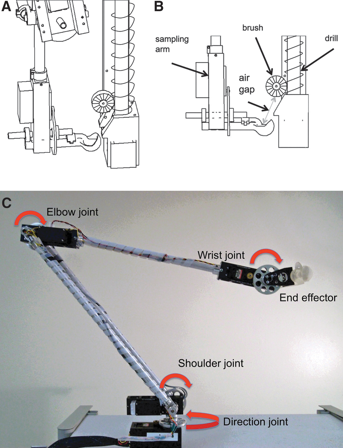
The chosen arm design (Fig. 2) has four joints—a “shoulder” with two orthogonal axes of rotation, an “elbow” and “wrist” each with a single axis of rotation—that provide a total of four degrees of freedom. The arm is long enough to reach the drill work area; however, the device does not contact the drill. It either catches samples that are brushed off the drill or scoops up samples from a cuttings pile. This is the way the air gap, a planetary protection requirement, as discussed above, is maintained.
Based on similar designs from other industries, we selected four concepts for end effectors that would involve the fewest moving parts and rely on mechanical ejection of the sample rather than gravity alone (Fig. 3). The four designs include the following: the conical screen (from the construction industry), the bucket dredge (from the salvage industry), the soil test corer (from the agricultural industry), and the ice cream scoop or melon baller (from food service).
Design drivers for sampling device end effectors. Color images available online at
The screen concept was eliminated because it could only capture and transport cohesive soil and not loose, sandy, or dusty soil. The dredge design was not pursued. It had the greatest amount of residue, 20%, because its corners had acute valley angles where soil could accumulate. The two remaining concepts, the corer and the scoop, were selected for further development and testing. These concepts are shown in Fig. 4. The design of the injector in the sample handle for control samples (organic-free blanks, positive biomarkers, etc.) is also shown. This control sample can then be delivered to the instruments following the same protocol as sampling from the drill. The controls are for end-to-end tests of the sample handling system.
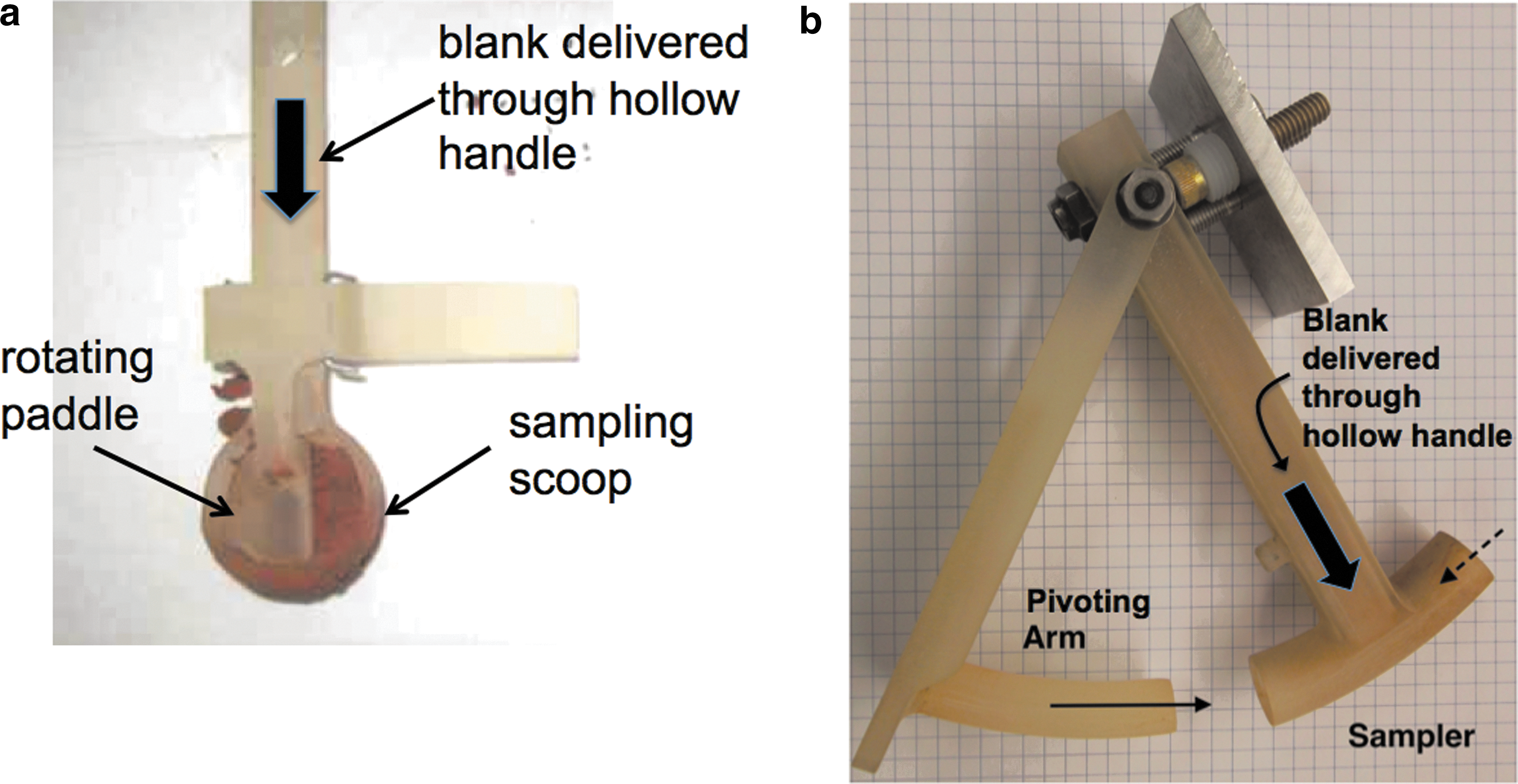
“Scoop” and “Corer” end effectors. (
The next step was to test the two remaining designs to determine whether they could work with a range of soil types expected in the northern regions of Mars. This range of soils includes modestly cohesive “crusty to cloddy” materials as seen by the Viking 2 lander (Moore and Jakosky, 1989) and the Phoenix lander (Arvidson et al., 2009) and strongly cohesive icy soil as seen by the Phoenix lander (Arvidson et al., 2009). We also wanted to test the extreme cases of noncohesive soil, as we might expect to see should the drill penetrate solid rock, or sample material similar to the weakly cohesive loose “drift” material seen at lower latitudes by Viking 1 (Moore and Jakosky, 1989).
As discussed in the next section on Analog Soils, we defined a set of six Earth analog soils that span a range of cohesiveness, which were chosen for mechanical qualities that bracketed the handling difficulty of the Phoenix soil. We used a high-cohesion clayey soil as the benchmark. Success with this stickiest type would ensure that all sample types could be released into an instrument funnel.
We tested the two types of end effector, the scoop and the corer, with these six soil types to see whether they could meet the basic requirements of sample collection and release for delivery.
3.1.1. Collection
For the Icebreaker mission, the soil samples are originally broken up and acquired by the drill, which augers the cuttings up to where a passive brush pushes them from the flutes (Zacny et al., 2013). The end effector of the sampling arm then collects a sample of these cuttings without touching the drill.
We tested collection in ambient conditions by measuring whether the amount of sample acquired by the device was in the 1–4 mL range. We derived that range from the amount of sample required by the Icebreaker instruments as follows: Alpha Proton − ray Spectrometer (APXS): 1.1 mL per analysis Signs of Life Detector (SOLID): 1.6 mL per analysis Laser Desorption Mass Spectrometer (LDMS): 1 mL per analysis Wet Chemistry Laboratory (WCL): 6 × 1 mL per analysis
The total number of instruments receiving sample in any 1-sol operation is two. The highest volume needed in any 1-sol operation is 7.6 mL (the volume needed by WCL and SOLID). The 7.6 mL volume requires two deliveries of soil by a 4 mL device.
3.1.2. Release
The end effector must be able to push the collected soil out and into an instrument intake by mechanical displacement. We tested release by measuring the amount of the original sample that was pushed into a 10 mL funnel used to model the intake of the science instruments.
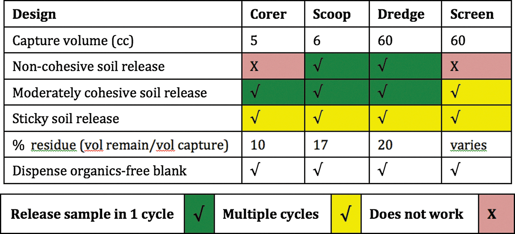
Figure 5 shows the results of the tests for the corer's and scoop's abilities to collect and release a range of soil types in room temperature and pressure conditions. The corer design, which relied on an enclosed plunger to dislodge samples, revealed a tendency to retain soil longer and to jam more easily than the scoop, which relied on a scraping paddle to dislodge samples. This was quantitatively measured in number of actuator cycles needed to dislodge samples. As discussed above, the ability to hold the sample in atmosphere to allow sublimation would permit delivery of a dryer sample. The scoop provides a larger (∼5×) surface area per unit volume of sample than the corer to allow this sublimation.

Summary of test results for the scoop and the corer at room temperature and pressure. Color images available online at
The analog soil testing of the end effectors brought them to TRL 3: “Experimental demonstration of critical function.”
3.2. TRL 4. End effector tested with arm assembly in Earth ambient conditions
The next step was to attach the scoop and corer to the robotic arm. When testing the end effectors by themselves, human strength and coordination were used to position the effectors and cycle their soil-pushing mechanisms. We then determined whether these steps could be duplicated with the use of robotic strength and coordination. This testing would show whether the actuators had sufficient strength to overcome cohesion and the ability to return to the sample collection position without touching the drill.
The driving software, arm, scoop (or corer) assemblies were tested within simulated spacecraft geometry at Earth ambient conditions with low- to high-cohesion soils. A laboratory bench was set up to resemble the geometry of a lander deck, with soil samples below the deck and instruments, the drill, and the sample handling system above it. The ability of the arm to return to the sampling position was especially important in helping satisfy planetary protection requirements by maintaining an air gap between itself and the drill. The arm's movement was further restricted to the dimensions of the Mars simulation chamber, which would be used in the next phase of testing. This facilitated the move from the lab to the Mars simulation chamber.
Our test bed used a commercial four-degree-of-freedom robotic arm to carry the end effector, driven by custom automation software. A six-axis coordinated arm controller was used to control the servos on the arm, giving the required repeatability. High-level control was implemented on a front-end Linux operating system.
The sampling device assembly was “graded” on its ability to (1) collect an amount of soil in the 1–4 mL range, the typical amount needed by our proposed Icebreaker instruments, (2) collect soil while maintaining a distance of 1 cm or more from the drill, (3) translate to one of three different instrument locations, (4) dislodge stuck soil, (5) deliver 1–4 mL soil into a simulated instrument funnel, and (6) minimize compaction to allow soil to fall through instrument screens.
The lab testing of the prototype device was done with mock-ups of the Icebreaker drill and the SOLID2 instrument (Parro et al., 2011). Soil samples were delivered to the scoop and corer, as they would be brushed off or fall next to the drill due to gravity. The total amount collected was measured in a 10 mL graduated cylinder. The sample delivered with each attempt was collected in a paper funnel placed over the mock-up of the SOLID instrument and transferred to the graduated cylinder for measurement. Photographs were taken of the delivered sample splatter pattern on the paper funnel, which graphically showed whether the sample was compacted by the end effector.
The arm was assembled with each of the end effectors in turn and run from the drill mock-up to the instrument mock-up. The arm driver software accurately moved the device to three different locations, parked near the drill, and collected soil in the 1–4 mL range needed by the instruments. Together, the arm and each sampling device successfully delivered increasingly sticky soil samples within the limits of the arm's servo torque of 5.4 N·m (765 oz·in.). Although the software that determined the arm position used no external reference points, the servos' internal reference system behaved well at room temperature and reliably returned the scoop to within 1 cm of the drill. This system was later proved to work in the Honeybee Mars simulation chamber as well, with the addition of a warm-up period.
Differences between the scoop and the corer were found when these devices dislodged their samples. The corer design required multiple cycles of its plunger to dislodge nearly all soil types, from noncohesive to highly cohesive. The corer also jammed if there were enough soil particles of the same size as the clearance around its plunger. The scoop only required more than one cycle of its paddle to dislodge moderate to highly cohesive soil. The scoop, however, retained more residue than the corer: 17% of original sample for the scoop versus 10% for the corer. Both were able to deliver at least 1–4 mL of soil to the simulated instrument funnel. The corer had the ability to dispense sample in measured amounts but also compacted the sample into cylindrical lumps as it did so. Compaction makes a sticky sample more likely to remain on top of a science instrument's inlet screen rather than falling through.
At this point in the design process, there was no clear mechanical advantage of the scoop over corer; however, based on the science objectives of the Icebreaker mission, we decided that the scoop's higher residue would be less troubling than the corer's tendency to jam and to compact soil. Residue is undesirable because it can mix with the next sample, but for our purposes the 17% residue would be acceptable. The science goals of the Icebreaker mission center on the detection of strong evidence for life in any sample, so mixing is of lower importance than successful delivery to instruments (McKay et al., 2013). The scoop's ability to deliver loose soil and allow sublimation outweighed its tendency to carry residue. For this reason, testing the scoop was given priority over testing the corer.
The result of testing at room temperature and pressure was the demonstration that the scoop, integrated with the arm, could acquire and deliver soil samples while avoiding contact with the drill. This demonstration raised the TRL of the sample delivery arm to 4: “Technology component and/or basic technology subsystem validation in a laboratory environment.”
3.3. TRL 5. End effector tested with arm assembly and drill under Mars conditions
Once we had a working prototype arm that could move sticky soil in Earth ambient conditions, our next step was to show that it would work as intended with icy soils in simulated Mars environmental conditions. In addition, we conducted an end-to-end simulation that included the drill and the SOLID science payload element (Parro et al., 2011; McKay et al., 2013). The simulation would go from “dirt to data”: dirt in a frozen icy column to data read out from the SOLID instrument electronics.
For our testing, we utilized Honeybee Robotics' large Mars simulation chamber in Pasadena, California (Fig. 6). This test chamber can provide pressures and soil temperatures consistent with Mars polar environments as seen by the Phoenix lander. Test pressures ranged between 680 and 853 Pa, at or below Phoenix pressures of 725–855 Pa (Haberle and Kahre, 2010), and soil temperature was kept below −20°C, compared with −58°C to −80°C for the air temperature seen by the Phoenix lander (Haberle and Kahre, 2010). The −20°C was sufficiently below freezing to cause the ice shavings to behave like sand and allowed a temperature gradient that caused sintering of the sample in the scoop. Soil cohesion due to temperature gradient was observed during the Robotic Arm Experiment on the Phoenix lander (Arvidson et al., 2009).
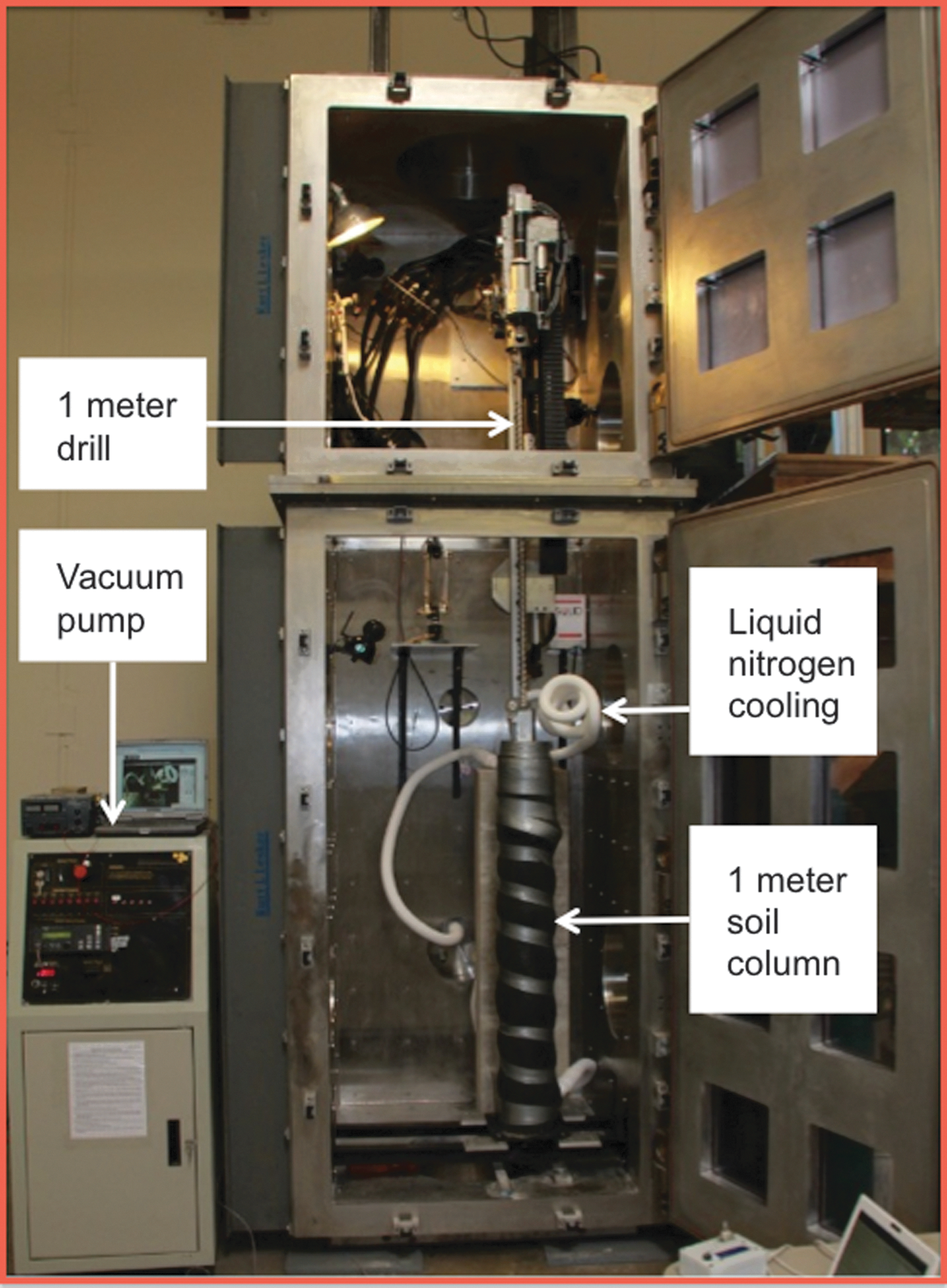
Honeybee Robotics Mars simulation chamber. Color images available online at
The automation software allowed reliable operation within the sealed chamber. The software relied on its internal servomotors' position feedback to return the arm to position and was unaffected by low temperature and pressure.
The arm reliably returned to position to collect soil from the drill while maintaining the 1 cm or greater distance from the drill during the chamber test. Our tests showed that the arm required a half-hour warm-up period prior to operations to meet the 1 cm air gap requirement. Future tests should include instrumentation to measure the temperature of the arm. The cold temperatures and reduced pressures within the test chamber improved the arm's ability to collect soil because the icy soil stuck to itself more readily than at room temperature. The crystalline icy soil was able to rest at a steeper angle of repose, and more sample could pile up on top of the scoop. Our results show that, after warm-up, the arm was as capable in Mars conditions as it was at Earth ambient conditions of moving a sample over the instrument funnel and running through its dislodging routine. This step, which required one rotation of the paddle to release the sample at Earth ambient, now required three to four rotations due to increased cohesion, but the routine showed it could, in due course, release 1–4 mL of soil into the instrument funnel.
3.3.1. Soil column composition
After hardware testing with soils that were sticky due to high organic content or other Earth-type chemical compositions, we tested the hardware with soils that were chemically similar to those at the Phoenix landing site. Clumpy, cohesive soil was observed at both the Phoenix and Viking 2 sites, possibly due to the presence of water and salts (Arvidson et al., 2009). We created a moderately cohesive soil mix with Mars Mojave Simulant (MMS) and known quantities of water ice, salt, and organics added, which we interspersed with some pure ice lenses. (See Fig. 7, example soil column.)
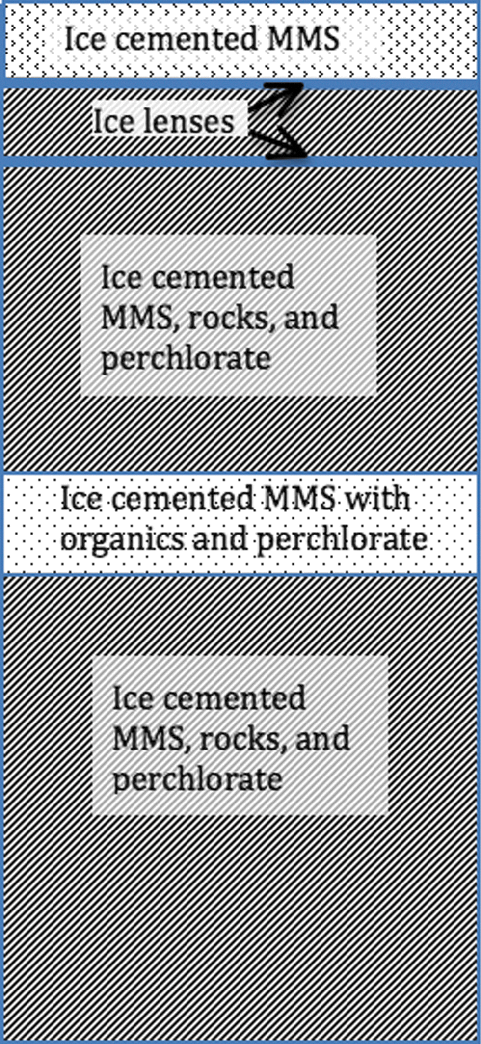
Example of a soil column used in chamber testing the sampling device together with the Icebreaker drill and SOLID instrument.
Finally, we observed that the sample delivery to SOLID met the instrument requirements. The sample fell within the 22 mm diameter input cylinder, was not compacted, and had a grain size of ≤0.5 mm (500 μm) due to the pulverizing action of the drill. SOLID was used to analyze the samples and revealed that they contained organics, thereby demonstrating the science telemetry end of the sample handling chain.
Success was measured by automation and mechanisms that allowed (1) repeated positioning of the arm to collect soil from the drill while maintaining ≥1 cm distance from the drill; (2) collection of 1–4 mL of soil; (3) movement of the sample from the excavated soil pile up to a deck-mounted instrument funnel, without touching the drill; (4) use of a fixed post near the instrument to activate the lever dislodging stuck soil; (5) release of 1–4 mL of soil into the instrument funnel without touching the funnel; and (6) delivery of the sample in a condition that meets the requirements for the SOLID instrument. (See Fig. 8 for a diagram of this operation.)
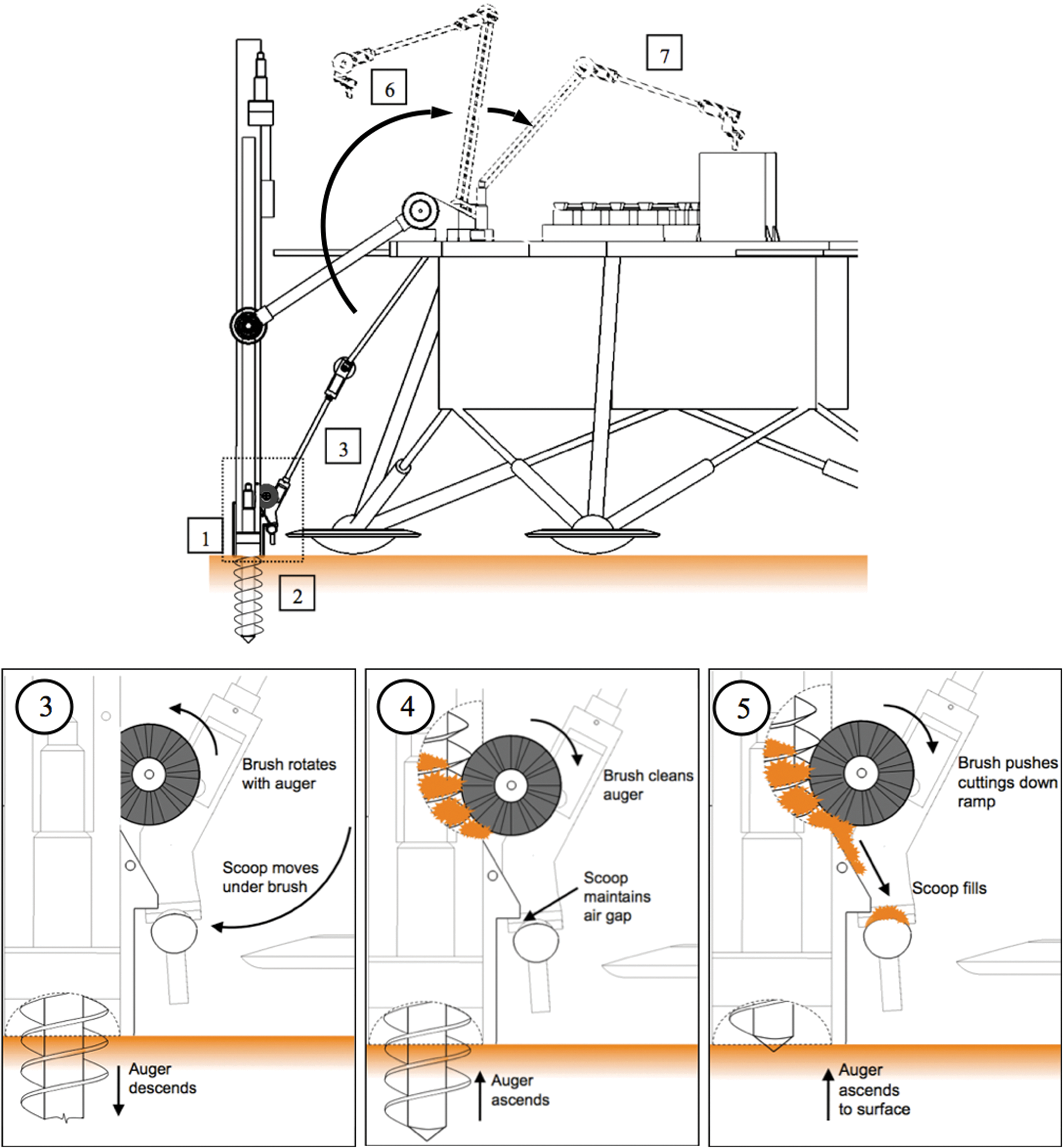
Diagram stepping through the sample retrieval operation. Color images available online at
Figure 9 shows the scoop design successfully capturing 5 mL of ice mixed with MMS from a passive brush mounted on the drill string. Note that the scoop does not touch the drill string while collecting the sample.

The scoop design successfully capturing 5 mL of ice mixed with MMS from a passive brush mounted on the drill string. Note that the scoop does not touch the drill string while collecting the sample. Color images available online at
3.3.2. Requirements of sample for the SOLID instrument
After the sample was delivered to the instrument funnel, it was tested to show whether it was suitable for analysis by the SOLID life-search instrument. The samples for the SOLID instrument were required to fall within 22 mm diameter input cylinder, have a volume of ≤1.6 mL, and have a grain size of ≤0.5 mm (500 μm).
Our tests in the Mars simulation chamber demonstrated that the material broken up and brought to the surface by the drill could be moved by the device to the input funnel in a condition that allowed SOLID to test it for signs of life, demonstrating the feasibility of the entire “dirt to data” process in a Mars-relevant environment. By demonstrating that the sampling device worked and was well integrated with collateral and ancillary systems, we achieved TRL 5: “Technology component and/or basic technology subsystem validation in a relevant environment.”
4. Analog Soils
As discussed above, the Viking 2 and Phoenix missions encountered sticky soils that challenged the soil handing equipment and impeded sample delivery to the science instruments. It is therefore imperative that sample handing systems for Mars be tested over a range of soil types, including highly cohesive soils. For proof-of-concept testing of designs, it is convenient to operate at room temperature and pressure. For room-temperature tests, we defined a set of six Earth analog soils that spanned a range of cohesiveness and textures. For tests in which frozen samples were used in the Mars simulation chamber, we constructed a test soil based on a mixture of ice, perchlorate salt, and MMS sand (Peters et al., 2008).
Our approach to selecting simulants differs from the way typical Mars simulants have been chosen. For the tests of the arm at Earth ambient, we chose soils for their shear strength (friction angle and cohesion) rather than their chemical or spectral similarity to martian soils (e.g., Allen et al., 1998; Peters et al., 2008).
Friction angle is influenced by the grain size distribution, the level of compaction, particle size, and their angularity. The soil angularity is dependent on soil textural maturity (i.e., soil particles become rounded after aqueous weathering). However, high aqueous weathering is not expected in young martian soils; hence soil particles will be mostly angular. Cohesion is influenced by cementing agents (e.g., Fe2O3) or electrostatic forces. Apparent cohesion can also exist due to capillary pressure (when soils are wet). Hence, cohesiveness is used interchangeably with stickiness.
We found that Mars hardware testing before Phoenix assumed that Mars soil would “be relatively dry sand and silt. These soils typically have negligible cohesion” (Perko et al., 2006). Hygroscopically inert simulants were valued because they enabled consistent hardware testing results regardless of ambient humidity (Peters et al., 2008). We were working, instead, to create soil that was highly cohesive even at room temperature, most likely due to its ability to absorb water.
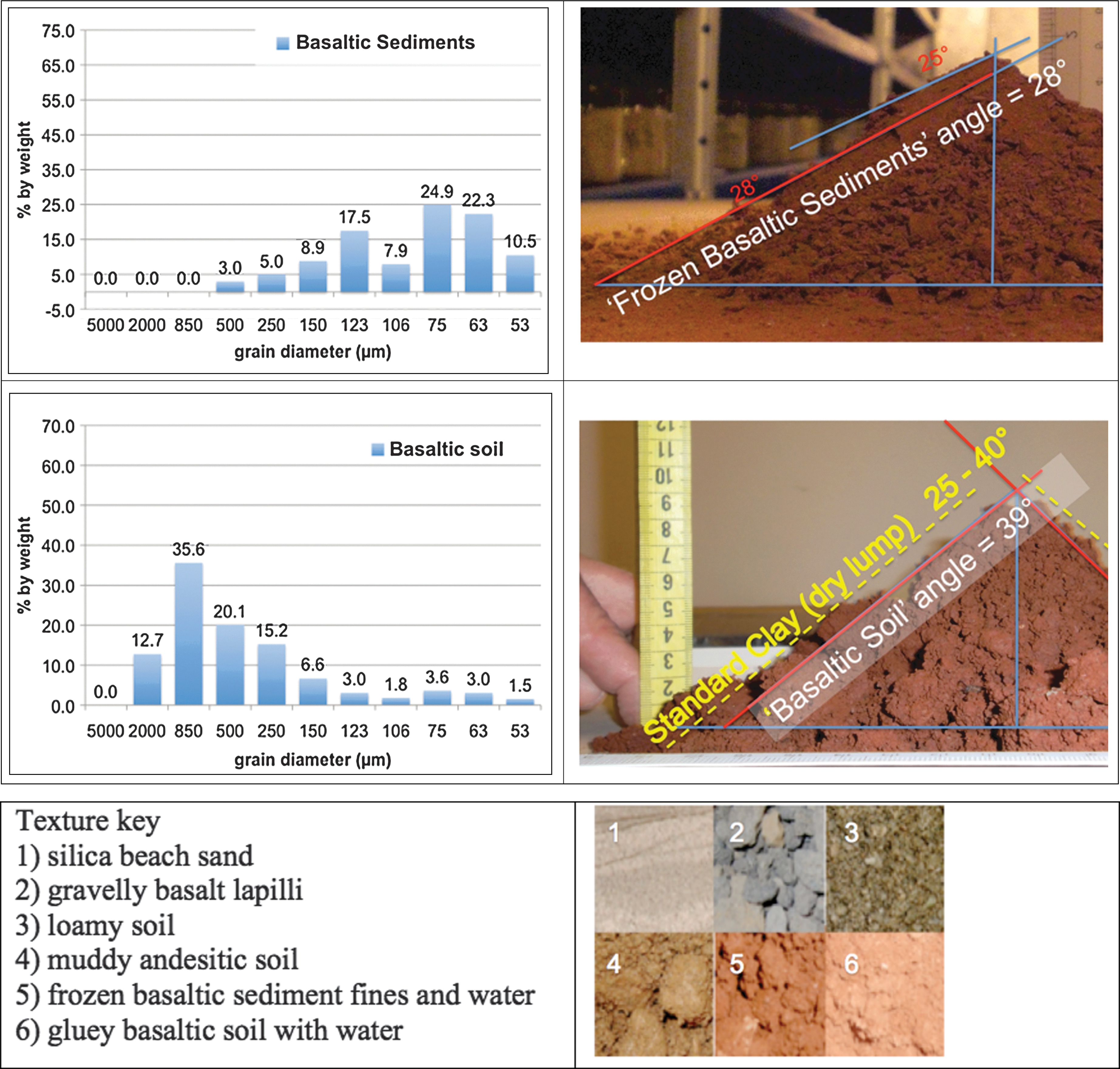
We selected six soils and analyzed them, using two parameters that were also used by landed Mars missions: particle size distribution and angle of repose (Perko et al., 2006; Goetz et al., 2010). For our particle size analysis, we utilized three methods. We looked at the larger components of the soils, using dry sieves with mesh sizes of 5000, 2000, 850, 500, 250, 150, 123, 106, 75, and 53 μm. For analysis of the smaller (<1 mm) components of the soil, we fed samples into a Microtrac particle size analyzer and reported mean particle diameter. A large difference between these two measurements indicates the presence of pebbles. We also spot-checked these particle size distributions with optical microscope counts. This allowed direct comparison with particle size data from the Phoenix camera and optical microscope (Goetz et al., 2010; Pike et al., 2011). From this comparison, we concluded that the range of soil properties in the six analog soils we used covered the range of soil mechanics at the Phoenix site. The analog soils we used are listed in Table 2 and are shown in Fig. 10.
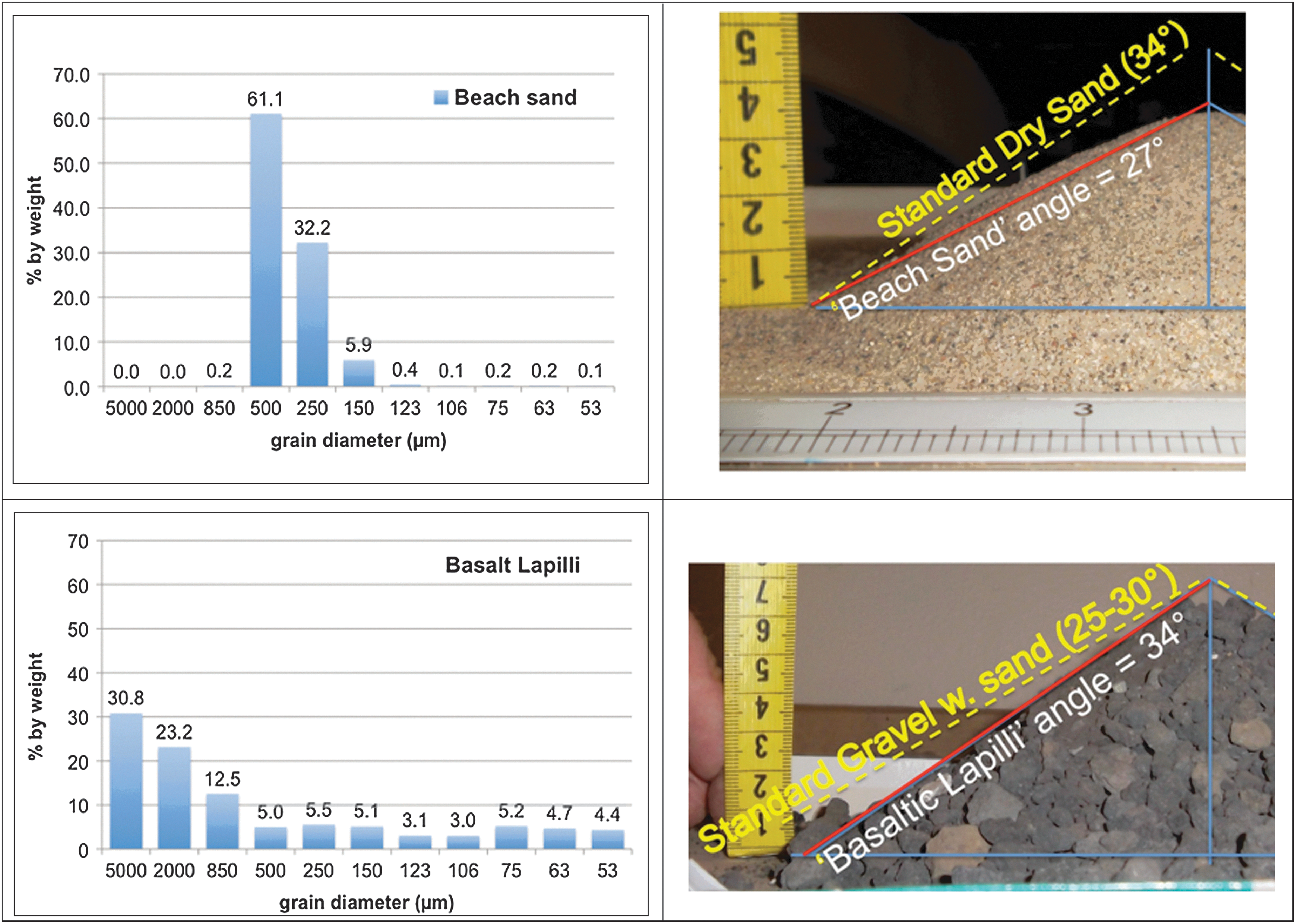
Types of samples used in testing. From top to bottom: (1) silica beach sand, (2) gravelly basalt lapilli, (3) loamy soil, (4) muddy andesitic soil, (5) frozen basaltic sediment fines and water, (6) gluey basaltic soil with water. Color images available online at
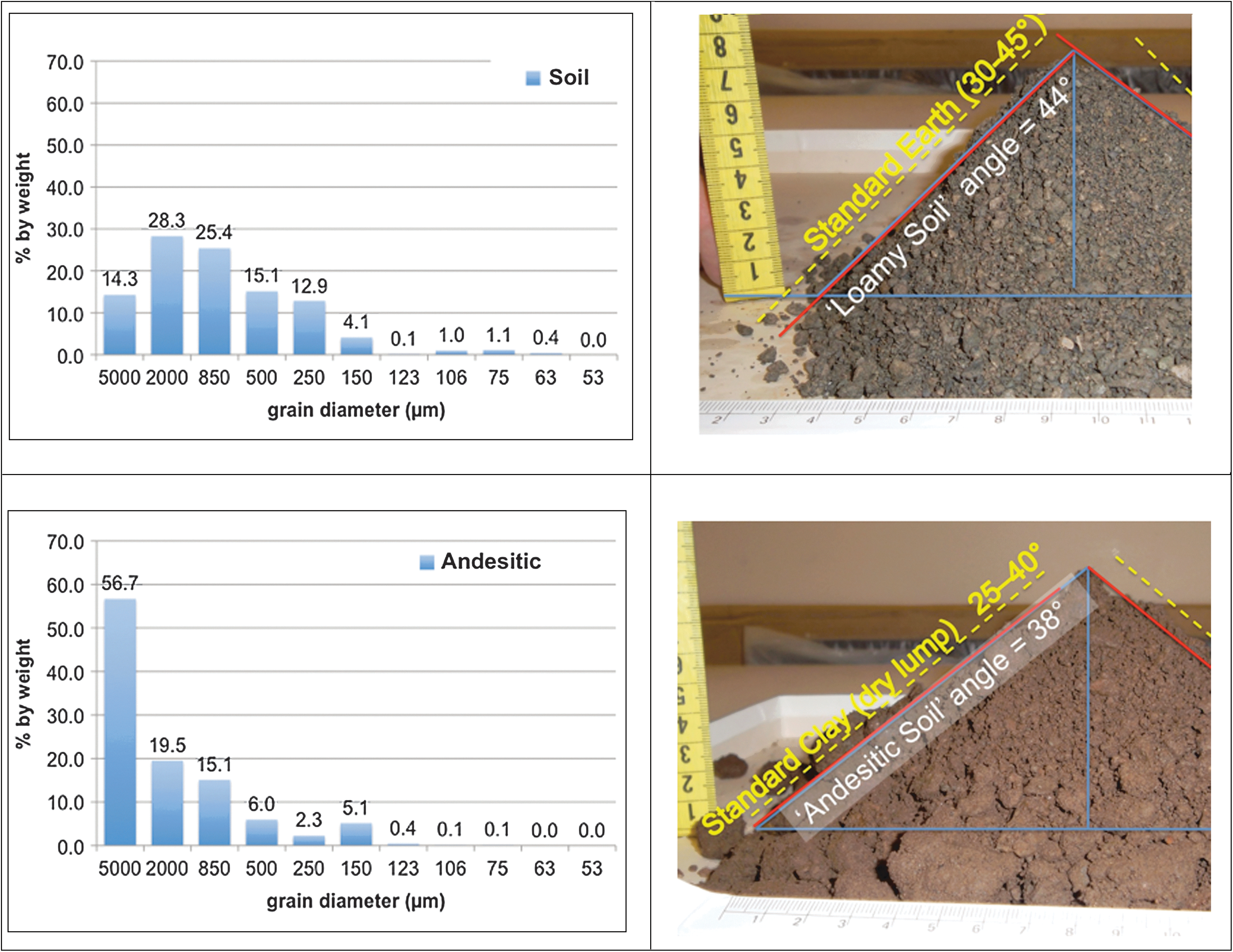
Of the six samples used in ambient tests, the basaltic soil bounded the upper end of the cohesiveness range with an angle of repose of 39°. It was the stickiest sample, and the ability to release this soil type proved to be the benchmark of a successful end effector. An example of its adhesive character was discovered when it was placed in a 10 mL graduated cylinder by gravity feed in order to measure its volume. It would not fall out when inverted, and it adhered so well it required twenty knocks against the lab bench to fall out of the cylinder. It would consistently leave the most residue in the end effectors (≥17%).
The basaltic lapilli was at the lower end of the cohesion range with an angle of repose of 34° and derived coefficient of static friction of 0.67. It was the easiest sample to handle. It would fall out by gravity feed alone and left negligible residue (<1%).
The six samples used in the lab also differed from one another in their ability to jam the moving parts of the end effectors. Dry beach sand, which was made up of particles nearly all the same size (see Fig. 11), caused the most jamming in the ambient tests. The plunger for the corer was immobilized by beach sand, and repeated cycling could not loosen the plunger. Greater force than the servo's 5.4 N·m (765 oz·in.) was required to overcome the friction of the beach sand. Basaltic lapilli and andesitic soil also caused jamming, but two or three attempted cycles of the plunger would loosen and then break up the jam.
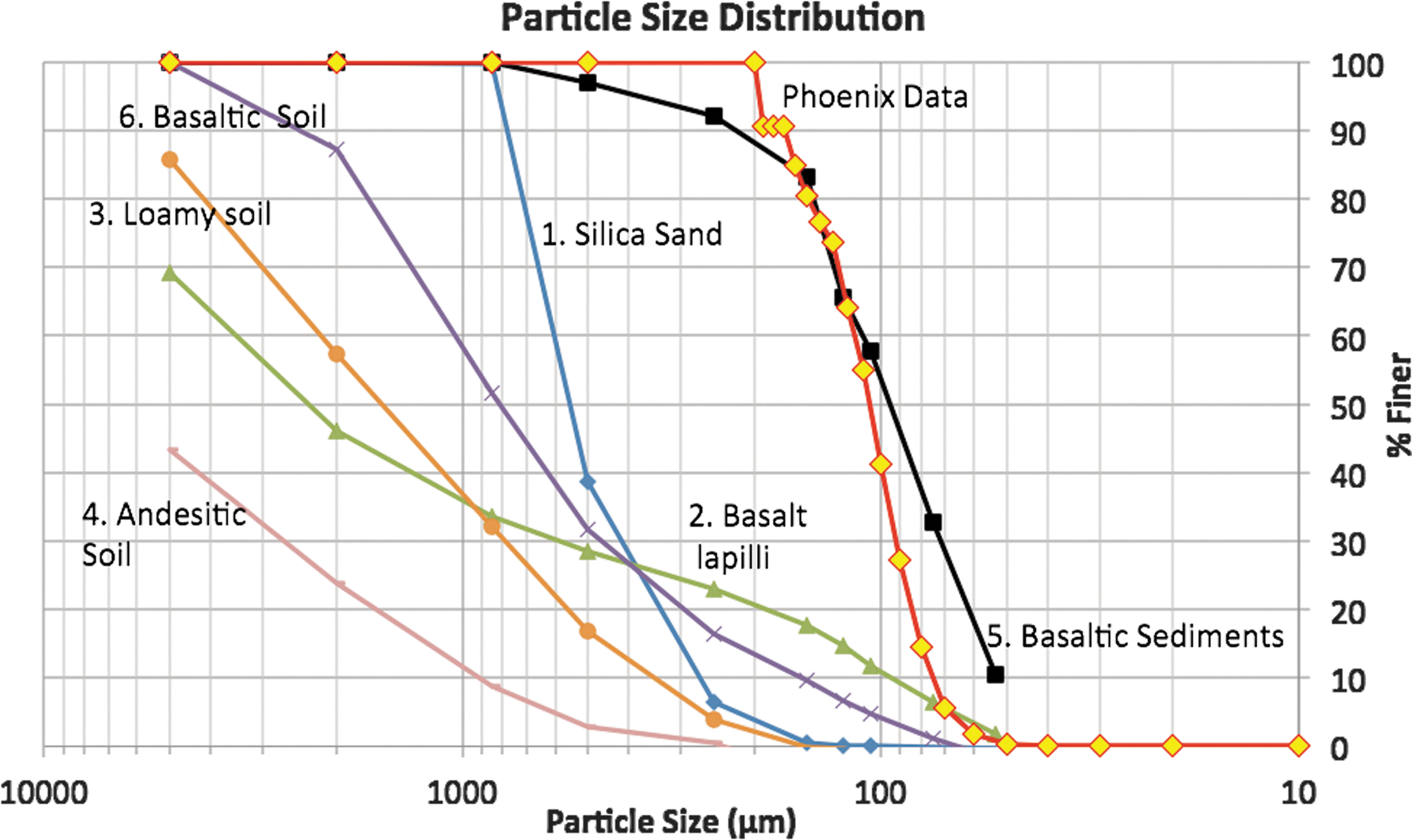
Particle size distribution of the six soils used in laboratory testing, along with Phoenix soil data derived from diameter counts (Goetz et al., 2010; Pike et al., 2011). (1) Silica beach sand, (2) gravelly basalt lapilli, (3) loamy soil, (4) muddy andesitic soil, (5) frozen basaltic sediment fines and water, (6) gluey basaltic soil with water. Color images available online at
For our last-room temperature test, we used basaltic sediments that had been mixed with water then frozen and finally brought into the lab and drilled. As shown below, as well as in Fig. 11, the frozen basaltic sediments most closely resembled the Phoenix site soil's mechanical properties. The cuttings had a weak adherence to the sampling device and left a thin, flourlike coating. Its angle of repose was 28–33°, and its derived coefficient of static friction was 0.65. Falling between the extremes of highly cohesive and noncohesive soils, it was neither the easiest nor the most difficult sample to manipulate. Our goal was to test our sampling device to greater extremes of soil mechanics than it was likely to encounter on Mars.
For simulations under Mars conditions, we constructed an ice-salt-soil mixture based on the Phoenix results, using MMS. Results of Phoenix's microscopic and Surface Stereo Imager (SSI) camera analysis of the surface soils (Goetz et al., 2010; Pike et al., 2011) indicate what a sampling device would have to handle in the top 5 cm below the surface. Beneath that depth, Phoenix encountered a layer of hard ice and icy soil (Arvidson et al., 2009). Although a small drill called the Rasp engaged this icy surface and acquired some icy samples, no telemetry was acquired to determine its mechanical properties (i.e., strength). However, we believe that the strength of this icy formation would be similar to icy soils found for example in the Dry Valleys of Antarctica (Zacny et al., 2013).
Mars Mojave Simulant was originally designated as a Mars simulant because it is chemically similar to martian soils characterized by the Spirit and Opportunity rovers, being “Plagioclase feldspar and pyroxene, along with minor olivine and magnetite,” which “tend to be the dominant minerals in both the MMS and the martian rocks” (Peters et al., 2008). At the time MMS was designed, Phoenix had not yet landed, and the soil profile it would eventually provide (Goetz et al., 2010) was, of course, unavailable as a design factor. In our tests, we assumed that MMS that was mixed with water and perchlorate salt and then frozen would be a suitable analogue of Phoenix site soils. Our analysis of that soil mix performed after testing showed that Mars soil analogues need to be physically modified to provide the clumping characteristics of Phoenix soils.
During analysis, it was shown that MMS sand, and even MMS sand that had been frozen, thawed, and drilled four times, was much coarser than the surface soils seen at the Phoenix site (see Fig. 12). “Phoenix soils appear to lack medium to large sand-sized particles in a wide size range (200–1000 μm)…no such particle could be unambiguously identified in any RAC or SSI images” (Goetz et al., 2010). Our particle size analysis showed that MMS sand was almost entirely composed of 250–500 μm sized grains. Although it may be chemically and optically similar to martian soil, its unimodal particle size distribution makes it mechanically unsuitable to represent the surface soils at the Phoenix site. MMS is offered in three forms: rock, sand, and dust (Peters et al., 2008). In future tests, MMS dust, rather than sand, mixed with water and perchlorate could be used as a more accurate surface soil analogue.
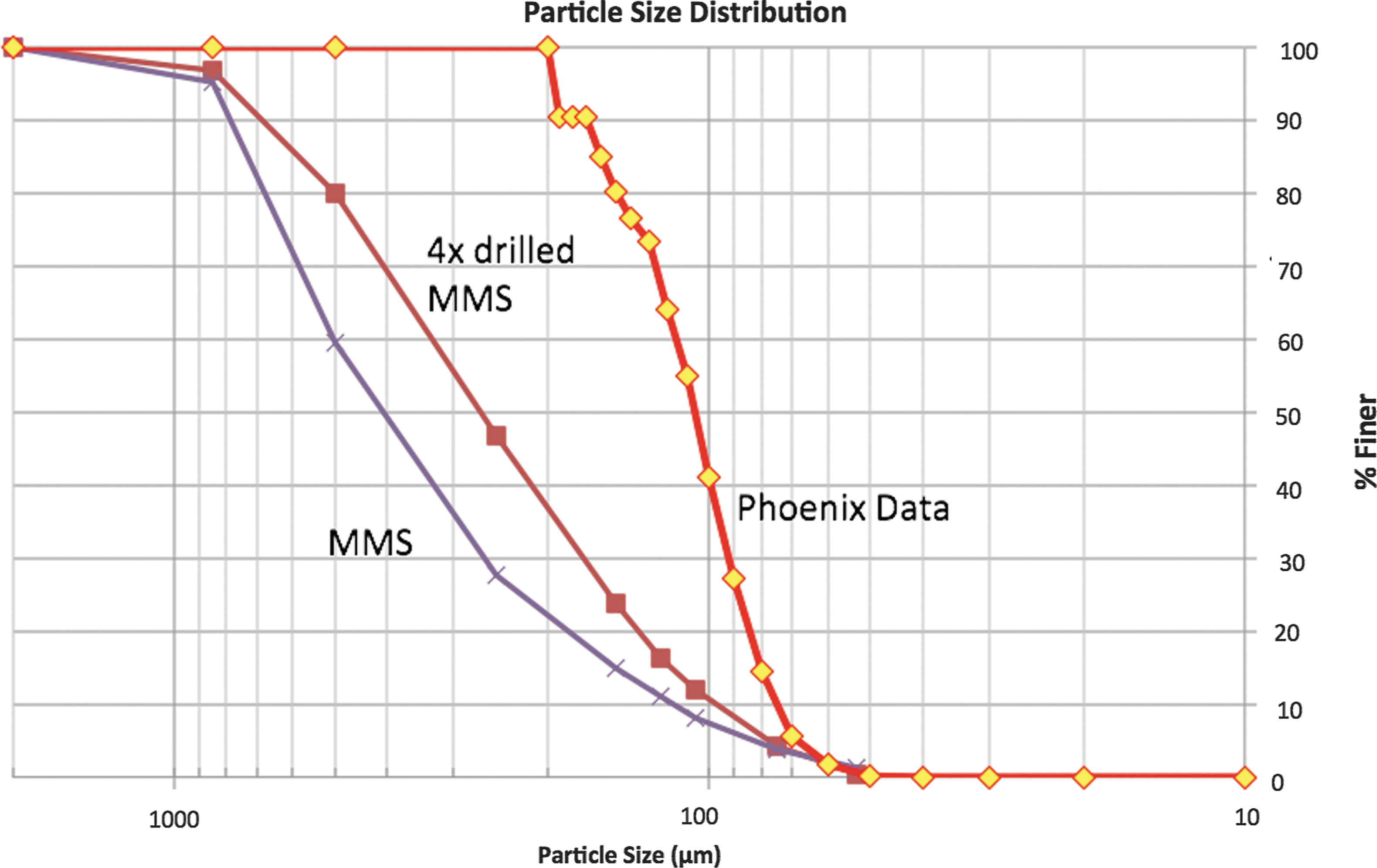
Soil characteristics from Mars simulation chamber tests in comparison with Phoenix soil. Color images available online at
The Icebreaker drill uses rotary percussion to break up solid ice and rock (Zacny et al., 2013), and this drilling action reduces the average particle size of soil (Zacny et al., 2006). From analog field testing of the Icebreaker drill in the Antarctic Dry Valleys, on ice-cemented soil and massive ice, we have learned to expect rock or ice pulverized by the Icebreaker drill to have a particle size ≤6000 μm and an average size of 500 μm. By this measure, MMS sand is a good analogue for rock pulverized by the Icebreaker drill, since it has a size distribution of ∼400 μm at 50% finer (see Fig. 12).
However, though unaltered MMS is a good analogue of rock pulverized by the Icebreaker drill, will it still be a good analogue after being drilled itself? We analyzed the MMS before and after drilling to characterize the drill's transformation of soil. Figure 12 shows characteristics of MMS before and after being altered by repeated drilling in comparison with soil data from the Phoenix site. We found that the drill decreased the average particle size from 400 to 250 μm, a reduction of about 150 μm. An analogous rotary percussive drill test with lunar simulant showed about an 80 μm reduction (Zacny et al., 2013). A rule of thumb might be that any sized particle already present in martian soils would probably be reduced by ∼100 μm by the action of the Icebreaker drill. So the MMS sand as altered by drilling was finer (250 μm) than drill cuttings of icy soil in the Antarctic Dry Valleys (500 μm). We expect that soil delivered from the Icebreaker drill on Mars would also have reduced particle sizes.
The scoop was only tested on the drilled MMS sand in the Mars simulation chamber. A more rigorous test of the arm's sample handling ability would be to drill into solid basalt in the Mars simulation chamber and test the arm's ability to handle those cuttings. However, our ambient testing with beach sand (50% finer than 500 μm) provided a good starting point.
5. Particle Size and Jamming
As part of this study, we considered the factors that can lead to mechanical jamming in sample handling systems. We review these factors here as a guide to future sample handling systems. Jamming is particularly relevant to sample handling for astrobiology missions, which require small samples to be transferred to instrument intake systems, typically without lubricant to avoid contamination.
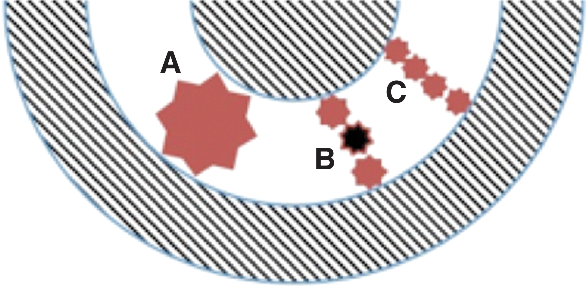
Figure 13 illustrates jamming modes. A clearance between moving parts should not be equal in size to the most common particle size—this is a recipe for jamming (Fig. 13A). Also, clearance should not be equal to three of these particles together. Three particles acting together tend to form bridges and lead to clogging of the device (Fig. 13B). It is hypothesized that the middle particle acts as a keystone to the impromptu bridge. A breadth of four particles lacks a keystone and does not cause clogging (Fig. 13C).
Jamming or seizing of moving parts. Color images available online at
The scoop proved more robust than the corer because its moving part, the paddle, was attached at a single pivot point. This created an angled clearance between the two. When particles were pushed into the gap between the scraper and the scoop, the scraper could wobble away from the obstruction. The corer's plunger was circumferentially bounded along its sides by the collection cup, with a parallel clearance, and was restricted in its ability to move away. Quite strong jamming could occur with one or two particles of just the right size (see Fig. 14). It is recommended that future designs use moving parts that are not bounded by stationary parts by more than 180° and that angled clearances are used that can allow particles of different sizes to pass through.
Jamming due to circumferential restrictions. Color images available online at
6. Conclusions
We designed and constructed a sampling device suitable for a life-search mission to Mars and raised this prototype hardware from TRL 1 to TRL 5. This concept breaks the chain of contact between a potentially life-supporting special region and the spacecraft while delivering sticky, icy soils to instruments. Our team demonstrated the sampling device's engineering feasibility in a relevant end-to-end environment. We successfully operated the hardware in Mars polar temperature and pressure and tested the ability of the Icebreaker drill and the SOLID life-search instrument to work together. This concept may be of interest within the Mars robotic mission community, including those prospecting lower latitudes for ice as a resource for human missions and those exploring the polar regions in search for evidence of life.
In the process of advancing the sample handling design from TRL 3 to TRL 4, we completed proof-of-concept testing in Earth ambient conditions. We verified the arm's abilities to handle the cohesive soils seen in the top 5 cm at the Phoenix site and the coarse-grained drill cuttings we might expect from the ice-cemented layers below. The sample delivery difficulties seen by the Phoenix lander were replicated and exaggerated in our tests. The arm was able to deliver highly cohesive soils (angle of repose 40–44°, derived coefficient of static friction 0.97) that were stickier than those reported by Viking 2 at 39° (Moore and Jakosky, 1989) and at the high (sticky) end of those seen by the Phoenix Lander at 29–47° (Arvidson et al., 2009).
While the sampling device was undergoing Mars simulation chamber tests to raise its TRL to 5, we characterized its abilities to work with the Icebreaker drill and SOLID instrument in a temperature gradient environment. We replicated the sintering of sample to a scoop, as seen by the Phoenix lander (Arvidson et al., 2009) and proved our design could dislodge samples in this condition and deliver them into an instrument funnel.
The arm's success in the chamber tests proved the feasibility of using an air gap to prevent forward contamination. Contamination concerns were addressed by using automation software to position the sampling arm near the drill without touching it while collecting cuttings from the drill's passive brush. In the future, the arm's automation will be incorporated in the drill automation program (Glass et al., 2011) so that timing, placement, and fault recovery can be further coordinated.
We found that the scoop-and-paddle design was the most successful in acquiring and discharging sticky samples. The scoop was rounded with no corners where soil could stick, and the paddle had an angled clearance to the scoop avoiding the jamming seen in parallel clearance devices when scraping off cohesive sticky soil.
The results of this study suggest several possibilities for future work. Further research into low-friction or nonstick coatings, materials with greater surface hardness, and designs that allow reduction of thermal gradients would help avoid jamming and optimize delivery of icy soil.
While our ambient testing used a wide range of soils, from noncohesive to highly cohesive, our Mars simulation chamber testing used only moderately cohesive soil (angle of repose 27–30°, derived coefficient of static friction 0.51). Future tests should involve more cases that bracket a range of cohesive rock cuttings within the Mars simulation chamber, with added dust as a possible cohesive factor, to show the limits of the arm's abilities. Added temperature sensors on the scoop and arm motors will allow better comparison with Phoenix results. A flight version would replace the analog servomotors used in this effort with actuators with full closed-loop control and absolute position feedback with the use of quadrature encoders.
We suggest that a wider range of subsurface ice-cemented soil and rock cuttings from the drill should be used to test the arm. The Icebreaker drill has been thoroughly tested in the Mars simulation chamber with a large range of rock, ice, and other mixtures (Paulsen et al., 2011; Zacny et al., 2013). The arm should ultimately be tested with this same suite of sample types in the form of drill cuttings. In summary, our characterization of the Icebreaker drill's effect on soil, comparison of Phoenix soils to MMS, and our observations on jamming will be useful for development of flight hardware for soil sampling and analysis technologies on Mars.
In addition to collecting samples for in situ analysis, the Icebreaker mission can also collect samples to cache for possible Mars Sample Return (McKay et al., 2013). Future work on the arm design should investigate delivering selected samples to a cache box mounted on the deck with the instruments.
Footnotes
Acknowledgments
We'd like to thank the members of the extended team that made this testing and analysis possible. Thanks to the NASA and Lockheed Martin staff that supported the ambient testing at Ames Research Center: Roger Arno for his design work, Emmett Quigley for expert help in fabrication and modification, Ryan Walker for help with microscopic particle size analysis, and John Livacich for backhoe and contamination control advice and help with evaluation criteria. Mike Hecht for providing raw data from Phoenix soil measurements. This project was supported by the NASA ASTEP and ASTID programs and Lockheed Martin IS&GS.
Abbreviations
MMS, Mars Mojave Simulant; SOLID, Signs of Life Detector; SSI, Surface Stereo Imager; TEGA, Thermal Evolved Gas Analyzer; TRL, Technology Readiness Level; WCL, Wet Chemistry Laboratory.