




Abstract
The future exploration of Mars will require access to the subsurface, along with acquisition of samples for scientific analysis and ground-truthing of water ice and mineral reserves for in situ resource utilization. The Icebreaker drill is an integral part of the Icebreaker mission concept to search for life in ice-rich regions on Mars. Since the mission targets Mars Special Regions as defined by the Committee on Space Research (COSPAR), the drill has to meet the appropriate cleanliness standards as requested by NASA's Planetary Protection Office. In addition, the Icebreaker mission carries life-detection instruments; and in turn, the drill and sample delivery system have to meet stringent contamination requirements to prevent false positives.
This paper reports on the development and testing of the Icebreaker drill, a 1 m class rotary-percussive drill and triple redundant sample delivery system. The drill acquires subsurface samples in short, approximately 10 cm bites, which makes the sampling system robust and prevents thawing and phase changes in the target materials. Autonomous drilling, sample acquisition, and sample transfer have been successfully demonstrated in Mars analog environments in the Arctic and the Antarctic Dry Valleys, as well as in a Mars environmental chamber. In all environments, the drill has been shown to perform at the “1-1-100-100” level; that is, it drilled to 1 m depth in approximately 1 hour with less than 100 N weight on bit and approximately 100 W of power. The drilled substrate varied and included pure ice, ice-rich regolith with and without rocks and with and without 2% perchlorate, and whole rocks. The drill is currently at a Technology Readiness Level (TRL) of 5. The next-generation Icebreaker drill weighs 10 kg, which is representative of the flightlike model at TRL 5/6. Key Words: Drilling—Sampling—Mars—Mars drilling—Subsurface exploration—Ice—Search for life. Astrobiology 13, 1166–1198.
Table of contents
1. Introduction
A
None of these future missions, however, target the northern latitudes as landing zones. The latitudes above 43°N are of particular interest to astrobiology since it was determined that water ice might exist in the near-surface regolith (Byrne et al., 2009). The ice-rich ground is a promising target because the ice may have been habitable in the past and also might have protected organic remains from near-surface oxidization and cosmic radiation. Amid the cold temperatures and its radiation-absorbing properties, the top 1 m of ice-rich regolith on Mars could be the best location to search for organic biosignatures that would represent evidence of life (McKay et al., 2013).
This paper describes the development of a sample acquisition system for the Icebreaker mission, targeting the ice-rich permafrost of the northern latitudes of Mars (McKay et al., 2013).
The science goals for the mission are as follows: (1) Search for specific biomolecules that would be conclusive evidence of life; (2) Perform a general search for organic molecules in the ground ice; (3) Determine the processes of ground ice formation and the role of liquid water; (4) Understand the mechanical properties of the martian ice-cemented soil; (5) Assess the recent habitability of the environment with respect to required elements to support life, energy sources, and possible toxic elements; and (6) Compare the elemental composition of the northern plains with midlatitude sites (McKay et al., 2013).
The Icebreaker mission could be based on the 2007 Mars Phoenix and 2016 InSight landed platforms (Fig. 1). The Icebreaker sample acquisition system includes a 1 m class drill, which will be deployed by way of a 3-degree-of-freedom (DOF) arm. An integral part of the drill system is a triply redundant sample delivery subsystem that includes a 5-DOF robotic arm with a delivery scoop (Davé et al., 2013), end-to-end pneumatic sample transfer, and the drill deployment arm that would position the tip of the drill with its captured sample above an instrument sample inlet cup (Zacny et al., 2012a).
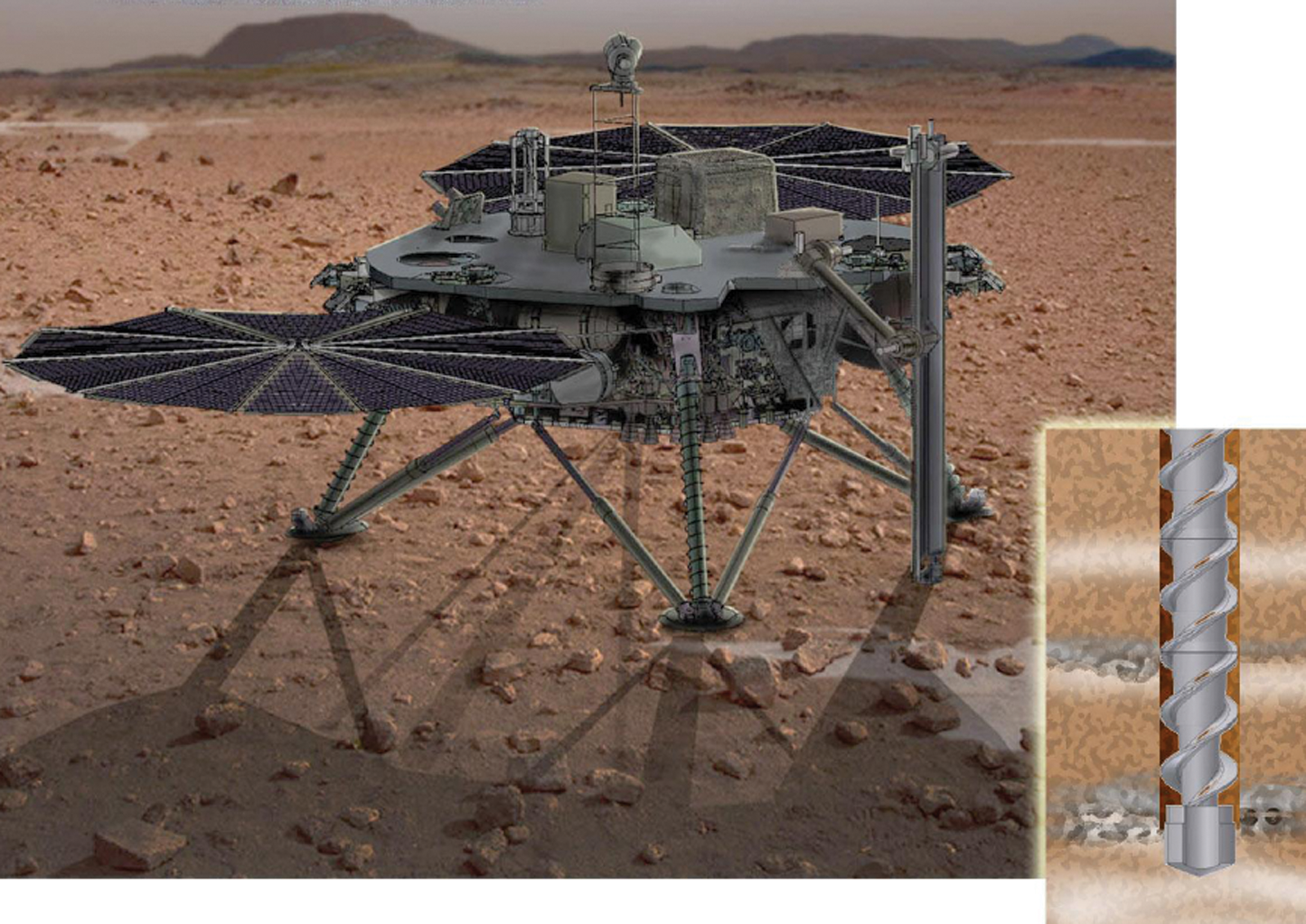
The Icebreaker mission would search for organic biomarkers at the northern latitudes of Mars by drilling to at least 1 m depth below the surface and transferring sample to life-detection instruments (Glass et al., 2011). Color images available online at
Since the drill mission targets Mars Special Regions as defined by NASA's Planetary Protection Office (Conley, 2011), the drill has to meet required cleanliness standards. The Icebreaker mission carries life-detection instruments, so the drill and sample delivery system must also meet stringent contamination requirements to prevent false positives.
In addition, the drill's telemetry such as penetration rate, power, and temperature could be used to infer subsurface strength, ice content, and downhole temperature. The latter data combined from different depths could be used to map a thermal gradient and heat flow, if subsurface thermal conductivity is known or can be estimated. As such, the drill can be viewed as an integral part of the sample delivery chain and is more akin to an instrument than mission-enabling hardware (e.g., robotic arm).
2. The Martian Near Subsurface: Experience from Past Missions
Thus far, there have been only six missions that have deployed excavation tools on Mars. These are Viking 1 and 2, Mars Exploration Rovers (MER) Spirit and Opportunity, Mars Phoenix, and the Mars Science Laboratory (MSL). Table 1 lists these six missions along with the type of excavation tool deployed.
The first excavators deployed on Mars were the scoops on the Viking 1 and 2 landers. The purpose of the scoop, called the Viking Surface Sampler Assembly (SSA) and shown in Fig. 2, was to acquire, process, and distribute samples to various instruments (Seger and Gillespie, 1974). The sampler consisted of a 3 m long rolled-up tubular boom with a collector head at its end. The extendable/retractable boom combined with the integrated azimuth/elevation gimbal allowed the collector head to be placed to any location within the articulation limits of the boom. The collector head, with its solenoid-operated lid, backhoe, and 180° rotation capability, was designed to acquire samples from a variety of potential surface materials and to deliver raw samples or 2000 μm sieved samples to the various experiments. The backhoe permitted surface trenching operations, collection of magnetic surface materials, and the brushing of surface materials overlaying bedrock.
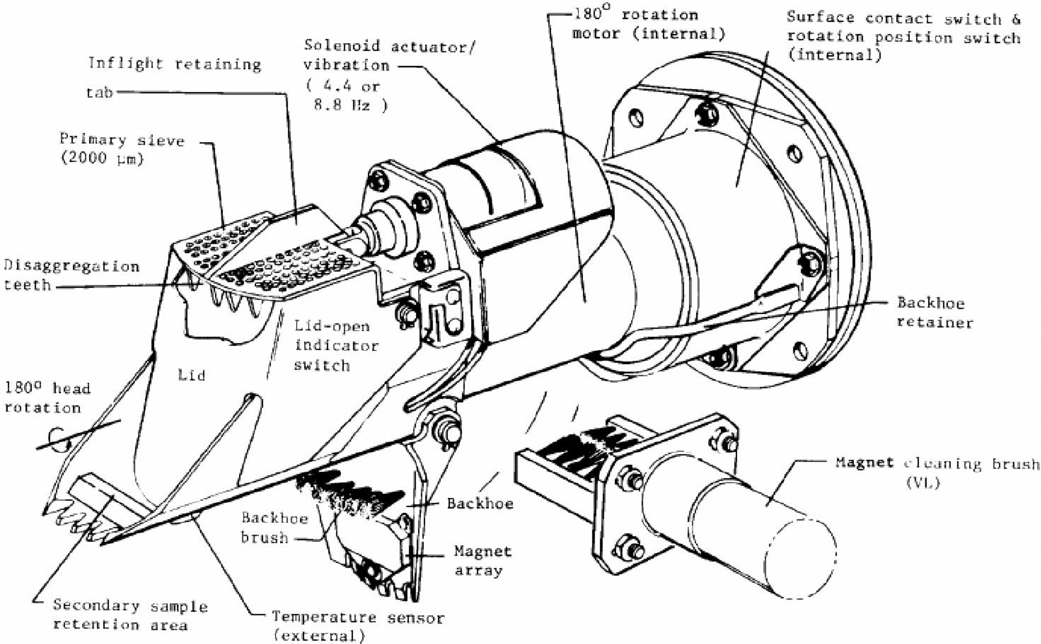
Components of the Viking Surface Sampler Assembly (SSA). Credit: NASA.
Additional soil processing mechanisms were integrated with the gas chromatograph–mass spectrometer (GCMS) and the biology instruments. For the GCMS, the sample was sieved through a 2000-micron sieve, crushed to less than 600 microns, sieved through a 300-micron sieve and finally metered 1 cm3 and delivered to the GCMS instrument. For the biology instrument, the sample was sieved through a 1500-micron sieve, metered to 7 cm3, and finally delivered to the biology instrument.
Although the Rock Abrasion Tool (RAT) deployed on MER Spirit and Opportunity is not technically an excavator but a grinder, it is nevertheless a tool that has successfully penetrated dozens of martian rocks (Gorevan et al., 2003). The primary goal of the 680 g 10 W RAT shown in Fig. 3 was to grind away a 45 mm diameter and a few millimeter–deep hole and expose the virgin rock to arm-mounted instruments such as the Alpha Particle X-Ray Spectrometer (APXS), Mössbauer Spectrometer, and Microscopic Imager (MI). Removing the first few millimeters was imperative to the success of the missions, since martian rocks are covered in weathered and oxidized crust and these crusts are not representative of the underlying rock. As such, the RAT is akin to a geologist's hammer that breaks the rocks open to reveal fresh surfaces.
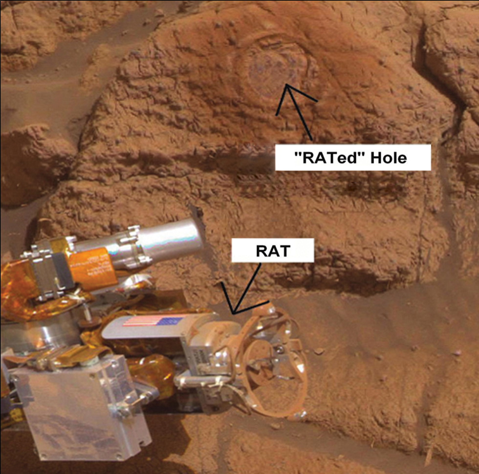
Mars Exploration Rovers' Rock Abrasion Tool (RAT) and a 45 mm diameter and few millimeter–deep RATed hole. Credit: NASA. Color images available online at
To date, the RAT on MER Spirit performed 92 brushings and 15 grinds, while the RAT on Opportunity has performed 31 brushings and 41 grinds. It should be noted that rocks at Gusev Crater, where MER Spirit landed, are much harder than rocks in Meridiani Planum, where MER Opportunity landed. This explains the greater number of grinds at Meridiani Planum. Since the MER Spirit mission ended, that RAT cannot be used any longer. However, the RAT on MER Opportunity is still being used as a brushing and a grinding tool.
The 2007 Phoenix mission was the first mission to land at the northern polar regions of Mars (Smith et al., 2009). The lander carried two instruments that required solid samples: the Thermal Evolved Gas Analyzer (TEGA) and the Microscopy, Electrochemistry, and Conductivity Analyzer (MECA). To enable sample acquisition and delivery, the mission included a scoop mounted at the end of a 4-DOF robotic arm (Fig. 4). The scoop, called the Icy Soil Acquisition Device (ISAD) also included a 6.35 mm diameter tungsten carbide drill bit called the rasp, to enable penetration of icy regolith (Chu et al., 2008). During the mission operations, the scoop was initially used to remove the layer of loose regolith covering ice-bearing material, and the flat-edged blade underneath the scoop was then used to scrape away icy regolith and form a more uniform surface for the rasp tool. Once the icy surface was prepared, the robotic arm preloaded the ISAD against the surface with 40 N in such a way that the rasp tool would press firmly against the icy regolith. The rasp cutting tool was engaged for approximately 30–60 s, and during this time icy-regolith shavings ballistically fell to the back of the scoop. The major problem the sampling system experienced during the mission occurred when delivering icy regolith. The regolith was found to be sticky and not only had a hard time flowing out of the scoop but also did not easily flow through the screens above the instrument inlet ports. The rasp subsystem included a set of features for vibrating the scoop; vibration helped but did not eliminate the problem.
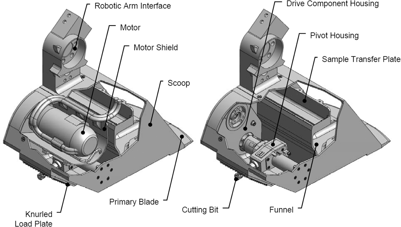
Components of the Mars Phoenix 2007 Icy Soil Acquisition Device (ISAD).
The regolith at the Phoenix site was found to contain 0.4–0.6% wt perchlorate (ClO4) (Hecht et al., 2009). It has been postulated that, if temperatures are high enough, it is possible for the ice and the perchlorate-rich regolith to form a wet super-eutectic solution (Chevrier et al., 2009). This could explain the cohesive nature of the regolith. This finding has tremendous implications for future missions requiring icy-sample acquisition and delivery subsystems. In particular, if a sample's temperature is high enough, relying on gravity to move the sample will make delivery either difficult or virtually impossible to accomplish. In addition, cross contamination between samples will be much worse for sticky samples.
There are three factors that could make martian regolith sticky: the presence of ice, perchlorate salts, and a large temperature differential between the sample acquisition system and the sample itself. It is impossible to eliminate the first two factors; however, it might be possible to control the third. For example, the sample acquisition tool could be placed within the shadow of the spacecraft, or the entire sampling operation could be performed at night, which might be up to 100°C cooler than the day. In addition, the sampler itself would need a built-in temperature sensor to continuously monitor the temperature during sample acquisition and either slow down or stop the process to prevent possible warming of the sample.
A recent study of new impact craters at the martian midlatitudes revealed the presence of water ice much closer to the surface than initially suspected. In particular, water ice could be present as close as 34 cm below the surface at a latitude of 43°N and within the top 10 cm at a latitude of 45°N (Byrne et al., 2009). This of course makes future missions to such low latitudes more enticing because of near-surface ice but also puts more pressure on the robustness of the sample acquisition system to deal with potentially ice-rich material.
The first mission to carry a drill to Mars is the ongoing 2011 MSL rover mission. The MSL mission consists of a 1-ton rover called Curiosity, the goal of which is to traverse martian landscapes and characterize past habitable environments recorded in sediments and rocks. In addition to contact instruments, it houses two of the most advanced analytical instruments ever built: Sample Analysis at Mars (SAM) and Chemistry and Mineralogy (CheMin). Both instruments contain 74 sample cups or cells and require samples in the form of rock powder or regolith. The powder for CheMin has to be smaller than 150 microns, while the powder for SAM needs to be smaller than 1 mm.
To address critical sample acquisition requirements, the Curiosity rover contains an end-of-arm mounted system called the Sample Acquisition, Sample Processing and Handling (SA/SPaH) system (Jandura, 2010). The SA/SPaH's two main elements responsible for sample acquisition include the drill, which is called the Powder Acquisition Drill System (PADS), and a scoop. The PADS shown in Fig. 5 is a rotary-percussive drill, with percussion provided by a voice coil mechanism (Okon, 2010). The PADS drill bit can spin at up to 150 rpm, while the percussive system can deliver up to 0.8 J per blow at up to 1800 blows per minute (BPM). To acquire a sample, the drill is first placed against a rock surface by a robotic arm with an axial preload of up to 300 N. This initial preload virtually eliminates the requirement for any subsequent motion of the robotic arm. The drill bit is protected within a sleeve that has a dual purpose of guiding the drilled cuttings (also referred to as rock powder) up the auger and also serving as an anchor for the rover in case of wheel slip on steeper terrains.
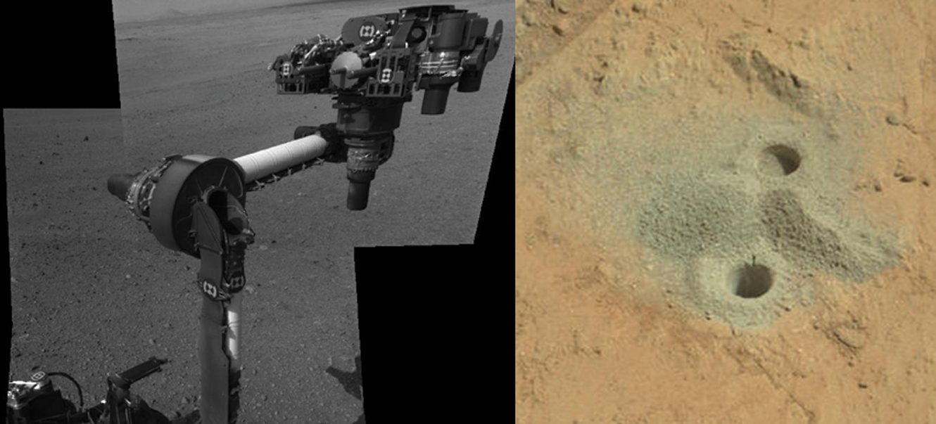
The Powder Acquisition Drill System (PADS) on the Curiosity rover and the first holes drilled (1.6 cm diameter) on Mars. Photo courtesy of NASA. Color images available online at
During a drilling operation, the drill penetrates the rock, and at the same time, the drilled cuttings travel up an auger and into a bit chamber that is connected to a powder processing unit, Collection and Handling for In situ Martian Rock Analysis (CHIMRA). The auger ends with a 1.6 cm diameter tungsten carbide bit. The drill can penetrate up to 6.5 cm depth and can capture cuttings from between the upper 2 cm and ∼5 cm depth. The top 2 cm is discarded onto the rock surface (this is desirable since the top layer of rock has been weathered and oxidized), while the bottom-most powder is always left in the hole by the nature of the sampling system that requires powder to move up some distance before it enters the auger tube section. Figure 5 shows the first two holes drilled into a rock called John Klein in the Yellowknife Bay area of Mars' Gale Crater. The upper hole was drilled on Sol 180 (Feb. 6, 2013) to a depth of 2 cm without collecting any rock powder as a test. The lower hole was drilled to 6.4 cm on Sol 182 (Feb. 8, 2013), and some powder was successfully delivered to the instruments.
Samples of regolith and other unconsolidated materials from depths of up to 3.5 cm are acquired with a clamshell scoop that is part of CHIMRA (Sunshine, 2010). The scoop was also designed to acquire unconsolidated samples from rover wheel–dug trenches. This would allow access to material as deep as 20 cm below the surface. In the nominal operation, the scoop can collect somewhere between 1 and 30 cc of material.
3. Considerations When Designing a Drill for Mars Surface Operations
There are several aspects that need to be considered when designing a drill with a goal of acquiring samples for analysis by very sensitive instruments. These aspects could be divided into the following categories: the science driven, the environment driven, the planetary protection driven, and the technology driven (Zacny et al., 2008; Zacny and Bar-Cohen, 2010).
3.1. Science drivers
The science drivers include the volume of the sample (since sample mass is very difficult to measure accurately), the particle size, the maximum allowable temperature during sample acquisition, whether the sample can be exposed to the atmosphere or particular gasses/moisture, and the target depth from which the sample needs to be acquired. Knowing the exact sample volume is critical to derive concentration values, since underfilling the instrument intake could lead to underestimated concentrations. Particle sizes are important for instruments that are sensitive to the largest particles. For example, the X-ray diffraction instrument (CheMin) on board the Curiosity rover requires particles smaller than 150 μm. Other instruments might require particles to pass through internal filters or that would not block internal conduits (Parro et al., 2008). The thermal environment of the sample is extremely important. Some minerals change crystal structure if certain temperatures are exceeded. In addition, in ice-rich permafrost increasing temperature may locally melt the ice.
3.2. Environmental drivers
Environmental drivers include gravity lower than that of Earth, very low temperatures, high diurnal thermal fluctuations, low atmospheric pressure, dust storms, and large distance from the Sun.
Low gravity is particularly challenging since drilling relies heavily on the weight on bit (WOB) or the vertical force applied on the drill bit. In general, the larger the force is, the faster the penetration rate. The Icebreaker mission (McKay et al., 2013) is based on the Phoenix platform; hence, the maximum possible preload will be the weight of the lander at approximately 350 kg scaled down by the martian gravity of 3.7 m/s2. This equates to 1300 N. However, it is very unlikely that the drill will be deployed along the center of gravity of the lander. In the most likely scenario, the drill will be initially in a horizontal position strapped to the deck of the lander. It can be deployed upon touch down by a 3-DOF arm and touch the martian surface some distance from the deck (because rocket plumes might contaminate the regolith in the immediate vicinity of the lander, it would be more favorable if the drill was deployed as far from the lander as possible). Assuming a lever arm ratio of 1:2, the maximum load will then be half of the original or 650 N. In addition, in practice a 3-DOF robotic arm will initially preload the drill Z-structure with a certain force; then the drill will start penetrating the subsurface along the Z-axis. The maximum WOB available for drilling must therefore be much lower than the force the drill Z-structure was preloaded with against the ground. To be safe, the maximum WOB must be at most 50% of the preloaded force applied to the Z-structure by the robotic arm. This further drops the maximum WOB from 650 to 325 N. If a factor of safety of 2 is added, this further reduces the WOB from 325 to ∼160 N. The factor of safety is required since a lander could, for example, touch down on a slope with one of its legs resting on a large boulder, causing the lander to tilt down slope. If a drill were deployed up the slope, the maximum WOB would then be much lower than if a lander was on perfectly flat ground. In summary, a lander that weighs 3500 N on Earth will be able to provide approximately 160 N WOB for the drilling system on Mars.
Low temperature and high thermal fluctuations affect the mechanical and electrical design of the spacecraft as well as its operation. In the case of mechanical design, it is important to avoid any instances where two materials with different coefficients of thermal expansion might contact each other. This would lead to high stresses and possible failures. Electronics need to be kept within a warm electronics box within tight temperature limits (for example −40°C to 40°C). Any other electronics outside the warm electronics box must have the capacity to withstand low temperatures or be integrated with heaters to keep them warm at night. Keeping the spacecraft warm could consume much, and in some instances almost all, of its stored electrical energy. Hence, other science instruments and tools such as drills need to be as efficient as possible when in use. Ice-rich regolith and ice-saturated rocks (i.e., porous rocks filled with water and then frozen) could be up to three times stronger at −100°C than at −10°C (Mellor, 1971; Zacny and Cooper, 2006). Even dry rocks get stronger at lower temperature, but the increase in strength is not as significant as in ice-rich materials (Heins and Friz, 1967; Kumar, 1968; Zacny and Cooper, 2007a). Higher formation strength will directly lead to higher drilling energy and WOB (Zacny et al., 2007).
Mars' atmospheric pressure brackets the triple point of water. In the northern lowlands of Mars, atmospheric pressure is above the triple point; hence, liquid water would be very unstable. When drilling aggressively (or inefficiently) into ice-rich regolith, the heat generated during the drilling process could be enough to sublime all the water ice underneath the drill bit cutters (Fig. 6). The water vapor generated in this process acts as a very effective drilling fluid, blowing the cuttings out of the hole in a similar way air drills work on Earth (Zacny et al., 2004). The major difference is that on Earth the air is provided from a compressor, while on Mars it is a result of ice sublimation. The benefit of such aggressive drilling is lower drilling power and higher penetration rate. In addition, the formation temperature remains at or near zero, since most of the heat is used up by the latent heat of sublimation. However, if the mission requires sampling water ice, such a sublimation effect has to be limited through efficient drilling and carefully planned drilling protocols that allow for ample cooling time in case the drill bit temperature gets closer to freezing. It should also be noted that heat generated during drilling could increase the temperature of ice-cemented ground underneath the drill bit and subsequently reduce its strength. This will result in a higher penetration rate and increased drilling efficiency.
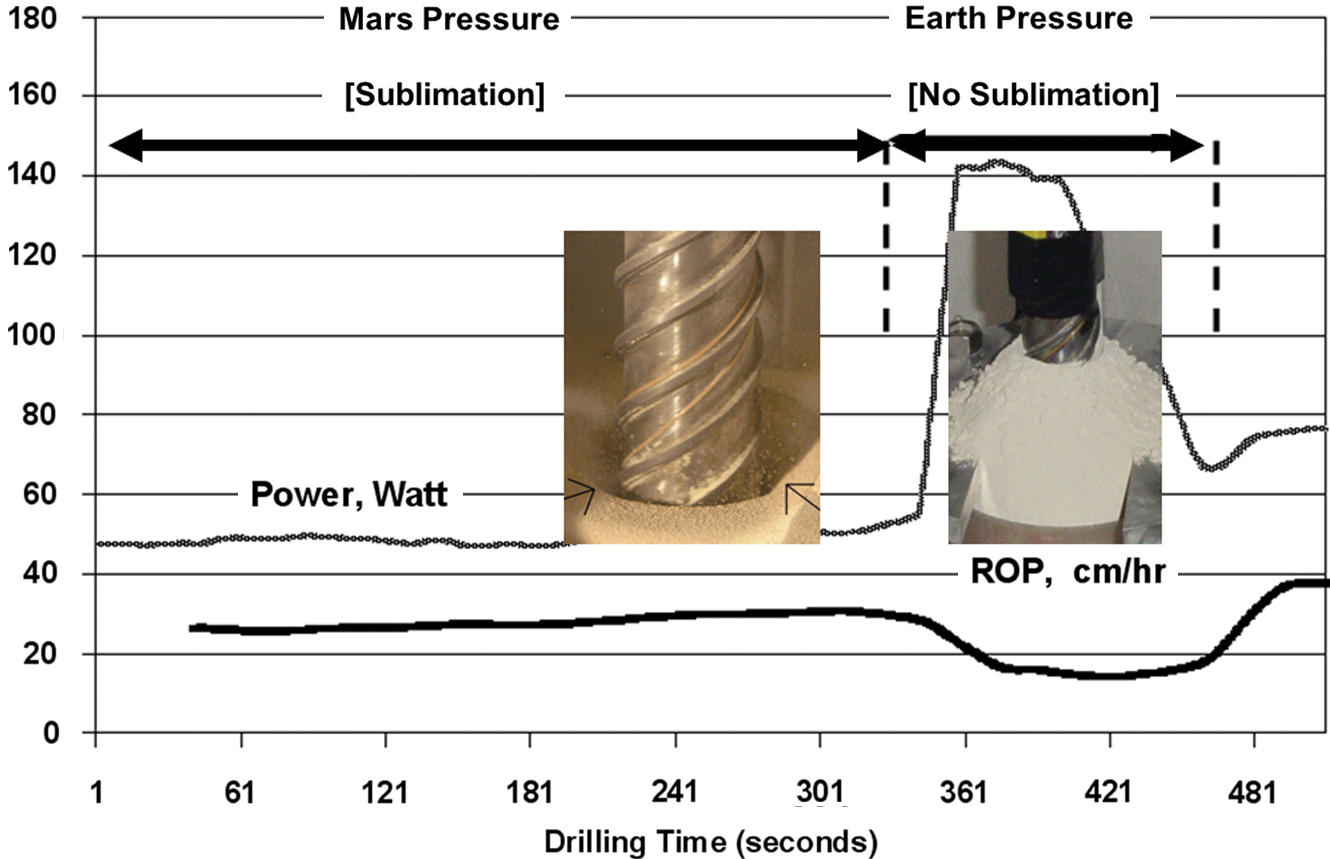
Drilling data under Mars and terrestrial atmospheric pressure in icy formation. Sublimed ice blows the cuttings out of the hole, which improves drilling efficiency (Zacny et al., 2004). Color images available online at
Low atmospheric pressure also reduces sliding friction between the drill bit and the rock as shown in Fig. 7 (Zacny and Cooper, 2007b). This is an important consideration for drilling since less heat will be generated during the drilling process and drilling energy will be lower. When interpreting drilling data, this will need to be accounted for as well, since lower drilling energy could incorrectly indicate lower rock strength. Sliding friction between two of the same or different metals needs to be investigated on a case-by-case basis. Coefficient of friction changes as a function of material type and atmospheric gas (Buckley, 1971; Niebuhr, 2007). Niebuhr (2007), for example, found that the coefficient of friction between titanium 6Al4V and hardened steel is 0.41 in air, 0.39 in nitrogen, and 0.33 in carbon dioxide atmosphere (all at 10–15 torr pressure). For 7075T-6 aluminum on steel, coefficients of friction are 0.45 (air), 0.41 (nitrogen), and 0.55 (carbon dioxide). Hence, nitrogen and air behave in a statistically identical manner for both metals, while CO2 increases friction for aluminum but decreases friction for titanium. Coefficients of friction of UHMWPE and PTFE on steel are ∼0.2 and 0.1, respectively, and are not significantly influenced by atmospheric composition.

Coefficient of friction between a drill bit and a rock as a function of WOB and atmospheric pressure (Zacny and Cooper, 2007b).
Eolian processes are the most important transport mode for micron-sized particles (Pike et al., 2011). This fine dust poses many problems for mechanical systems on Mars. In particular, any mechanical system that has moving parts (e.g., a Z-stage) needs to be protected from abrasive dust or robust enough to work when coated with dust. The dust may also have a high electrostatic charge due to tribocharging through contact with other particles or materials, or photoionization by the intense UV radiation. The settling of this dust can significantly reduce the efficiency of solar panels.
Sample transfer systems also need to be protected from dust to avoid dilution and contamination. Protection of a sample transfer system with wind guards is one way to address the problem of dilution or contamination, or even a loss of the sample if wind speed suddenly increases. The Viking landers and the MSL Curiosity rover implemented wind guards around the sample drop-off points to the instruments.
The large distance from the Sun affects not only the surface temperature but also energy density. The solar irradiance at Mars is 586 W/m2, which is approximately 40% that on Earth at 1353 W/m2. Therefore, solar arrays have to be much larger and ideally include a tracking device to point the arrays toward the Sun as much as possible. The low irradiance means that the spacecraft will have limited energy for housekeeping and science operations. Hence, any sampling system needs to be very efficient in reducing the energy burden on the spacecraft. Mars Phoenix had an average energy balance of 2 kWhr per sol; however, 50% of that was required for housekeeping.
In addition, given light-speed time delays in the range of several minutes, Earth-based teleoperation is not feasible for drilling operations on Mars. Drilling must be autonomous. Unlike terrestrial holes whereby subsurface is either known from prior drilled holes or could be evaluated through geophysical surveys, the subsurface of the drill site on Mars will be largely unknown.
3.3. Planetary protection drivers
Ice-rich permafrost on Mars is considered a Special Region; therefore, the mission qualifies as category IVc as defined by NASA's Planetary Protection Office (Conley, 2011). The Icebreaker lander might require complete sterilization by using, for example, dry heat microbial reduction (DHMR) in a similar manner as it was used for the Viking landers. From the standpoint of drill design, sterilizing an entire spacecraft would mean that all parts of the drill, including the electronics, would need to be designed to withstand DHMR, that is, baking at over 110°C for more than 24 hours (the Viking landers were baked at 111.7°C for 30 hours). This would simplify surface operations, since the drill could come in contact with any part of the spacecraft without the worry of possible contamination from “unsterilized” surfaces.
The alternative is sterilizing only the hardware that comes in contact with the subsurface, as was done during the Mars Phoenix mission. This would drastically simplify spacecraft design and cost since it would allow the use of materials, electronics, and heat-sensitive equipment that would otherwise be damaged by high-temperature treatment. However, the drill auger would have to be protected in some kind of biobarrier after sterilizing. In addition, any other hardware that comes in contact with a sample (e.g., a scoop) would also need to be sterilized. Since the Icebreaker mission would carry life-detection instruments, a high degree of cleanliness would be required to prevent false positives. The sample transfer sequences as well as proximity operations would have to be thoroughly tested out to avoid potential touching of the sample transfer hardware with unclean surfaces (e.g., instrument outer housing).
3.4. Technology drivers
Drilling power is not as much of an issue as drilling energy (though it still needs to be considered). Energy is the main factor because batteries store a finite quantity of electrical energy. Once that energy is used up, the drilling task would have to be delayed until the batteries are charged again (by a primary power source such as solar or nuclear). To better illustrate that point, consider two cases: (1) a 200 W rotary-percussive drill that takes 1 hour to drill a 1 m hole and (2) a 100 W rotary drill that takes 10 hours to drill to the same depth. The first, high-power drill requires 200 Whr, while the second, low-power drill requires 1000 Whr of energy, 5 times as much energy.
A comparison between a high-power Hilti TE-7A rotary-percussive drill and a low-power custom-built CRUX rotary-percussive Lunar/Mars drill in saddleback basalt rock is shown in Table 2. Although the Hilti drill required more power (720 W vs. 180 W for the CRUX), it drilled 3 times more efficiently and 12 times faster. There are other technology drivers associated with drilling; these are described in the context of drill development in the next sections.
4. The Icebreaker Mars Drill
The Icebreaker drill represents a state-of-the-art drilling system specifically designed to meet the science requirement of retrieving aseptic samples from ice-rich regolith. To meet this requirement, several trades were performed, evaluating various drilling and sample delivery approaches. The final selection of the drilling and sampling approach was driven by achieving the goal while minimizing the mission risk, and eliminating forward contamination (primary) followed by reducing system mass and increasing drilling efficiency (secondary). The following sections outline various trades performed in deciding optimum sampling system design.
4.1. Drilling depth
Drilling regimes could be divided into four distinct areas: surface, 1 m, 10 m, and deeper than 10 m (Bar-Cohen and Zacny, 2009). This division is based on the drill complexity, size, and mass rather than science goals.
Surface regime refers to a drill that is deployed from a robotic arm and penetrates a surface rock or ground to a depth from several centimeters to tens of centimeters. Examples of such drills include the MSL drill, the Luna 16 and 20 drills, and the Venera 13 and 14 drills (Bar-Cohen and Zacny, 2009). However, the goal of the Icebreaker mission is to search for past or present life, and this requires reaching depths below oxidized and irradiated regolith. It is believed that the minimum depth is 1 m, though greater depths will no doubt be more favorable (McKay et al., 2013). Therefore, a surface drill would not be applicable for the Icebreaker mission.
A 1 m class drill is characterized by using a single drill string to penetrate into the subsurface. In this regard, it is similar to a surface drill; however, the depth of penetration is almost an order of magnitude greater. As such, the drill actuators have to be more powerful so that the drill can be retracted in the event it is getting stuck, and the drilling algorithm would need to be designed such that it could manage a larger range of adverse drilling conditions. Examples of such drills include the Luna 24 drill and the SD2 drill (Drill, Sample and Distribution) on the Rosetta lander Philae (Bar-Cohen and Zacny, 2009).
A 10 m class drill is similar to a 1 m class system except that it includes a system for additional drill strings (e.g., a carousel) to enable the reaching of greater depths (Zacny et al., 2013a). The greater depth capability comes at a price of additional mass for drill strings and a drill string handling system. Drill strings would also require dust-tolerant mechanical and potentially electrical connections. Examples of such systems include the ExoMars drill, SCAD, and MARTE (Bar-Cohen and Zacny, 2009). A 10 m depth seems to be the most a drill can achieve when using an auger-based cuttings removal system. The limiting factor is the inability to efficiently move cuttings out of the hole. Drilling to greater depths will produce excessively high auger torque due to parasitic losses (auger rubbing on borehole wall) and friction produced by the movement of cuttings up the flutes. One approach to the removal of cuttings is to use compressed gas in the same manner as in terrestrial air drilling (Zacny and Cooper, 2007c).
For deep drilling in consolidated formations (e.g., ice or rock) where borehole collapse is not an issue, a wire line system can be used. Here, a drill in the shape of a tube is suspended by a tether and is periodically lifted out of the hole to empty the catch basket or drop off cores (if present). Examples of wire line drills include the Mars Deep Drill (MAD) and the Autogopher (Bar-Cohen and Zacny, 2009; Zacny et al., 2013b). If the formation is unconsolidated and the borehole is likely to collapse, a drill system would need a casing and a coil tubing approach.
Deep drilling is not possible in the near future unless substantial funding is set aside to start demonstrating such a technology and developing entry, descent, and landing (EDL) systems capable of landing >1 ton on the surface of Mars. A 10 m class drill is possible but carries substantial risk to the mission due to the requirement for connecting and disconnecting drill strings multiple times in the presence of dust. However, a single-string, 1 m class drill is feasible. A single string could be as long as the volume of the spacecraft allows it to be. For the Phoenix-sized lander, a drill could potentially reach 1.2 m. The SpaceX Red Dragon mission, which emphasizes placing the drill inside its Dragon capsule, could accommodate at least a 2 m long drill string (Stoker et al., 2012).
Because of the relative simplicity of the system and the ability for a single drill string to reach the required depth that might preserve organic material, it was decided that the Icebreaker drill should be a single-string system.
4.2. Selecting the best drilling method
There are at least three approaches to penetrating the ground: rotary, rotary-sonic, and rotary-percussive. The difference between the sonic and percussive systems is that, in sonic, the drill string vibrates, while in percussive systems a stress wave travels at the speed of sound from the top, where it is generated by an impact hammer to the drill bit.
Vibratory drills use piezo systems (Bar-Cohen et al., 2010) or a set of unbalanced wheels spun by a motor (Paulsen et al., 2012). In the latter approach, two wheels need to be used in order to cancel out side vibrations and loads. The principle behind vibratory drills is that they aim to put the drill string in resonance. Resonant vibration increases penetration force by fluidizing the regolith ahead of a drill bit and around a drill pipe. The latter has a tendency to reduce sleeve friction (friction between the drill pipe and regolith). The resonant frequency of a drill string is usually found by doing a frequency sweep and observing penetration rate. At a resonant frequency, the rate of penetration (ROP) drastically increases; hence, a driller continuously adjusts the frequency while monitoring the ROP. Such drills are used every day for regolith sampling (see for example the Boart Longyear LS600 Sonic Rig) and could also drill through weaker rocks, though at much lower penetration rates.
Percussive drills are ideally suited for hard rocks. Here, the drill string is struck by a hammer accelerated through various means such as a voice coil (Okon, 2010), pneumatic (as used in Hilti drills), magnetic (developed by Flexidrill), ultrasonic (Bar-Cohen et al., 2010), or a spring-cam (Paulsen et al., 2011). The selection of the most suitable percussive approach depends on the environment (in vacuum, air hammer will not work), whether variable impact energy or impact frequency is required, the complexity and robustness of the mechanism, and the greatest ratio of impact energy per mass of the system.
To determine the best drilling approach for Icebreaker, initially three drills with different drilling approaches were traded against each other. These include the DAME drill, which has a rotary drilling approach (Paulsen et al., 2006; Glass et al., 2008), the SONIC drill with a rotary-sonic approach (Paulsen et al., 2012), and the CRUX drill with a rotary-percussive approach (Zacny et al., 2010a; Paulsen et al., 2012). Figure 8 shows a summary of three different drilling approaches in 45 MPa Indiana limestone. Since the rotary system does not use additional sonic or percussive actuators, the required drilling power was lowest. On the other hand, SONIC requires the most power. In terms of energy, the most efficient system was found to be rotary, followed by rotary-percussive and rotary-sonic. Rotary-percussive required the lowest WOB and achieved the highest ROP.

Selected drill telemetry in 45 MPa Indiana limestone (Paulsen et al., 2012).
Additional tests were also performed in other materials such as soils, ice, and ice-cemented regolith (Zacny et al., 2013a). It was found that rotary systems work well in soft and non-abrasive formations, while percussive systems dominate in hard formations. Rotary-sonic systems did not perform as well as percussive and were only marginally better than rotary. In addition, WOB required to achieve a significant penetration rate in any formation was lowest for the rotary-percussive drills.
Based on these findings, it was decided to select rotary and rotary-percussive approaches for the Icebreaker drill. To enable an option of having the two different approaches, two independent actuators were employed for a rotary auger and the percussive mechanism. It is possible to use a single actuator with some kind of a clutch to disengage percussion, but that would mean the indexing (i.e., impact blows per every bit revolution) would have to be set at the beginning and could never be changed. In addition, a percussive system could not be used by itself (without rotation), and that flexibility might be useful during a sample drop-off operation.
The flexibility of separating rotary from percussive increases drilling efficiency. In soft rocks, only a lower-power rotary approach could be used, while in harder rocks a more powerful (and potentially more energy intensive) rotary-percussive system would be engaged. However, flexibility of using both approaches also puts an additional requirement on the drill bit cutter material and its shape. For percussive systems, cutters are made of softer and hence tougher tungsten carbide to prevent potential fractures. Cutters also have a rounded cutting edge to reduce stress concentrations. For rotary systems, where drilling mechanisms include the shearing of rock, cutters need to have a sharp edge. To retain the cutter's sharp edge for as long as possible, much harder (and in turn less tough or more brittle) tungsten carbide material is used. Alternatively, a polycrystalline diamond material could be used, though polycrystalline diamond compact cutters that use polycrystalline diamond material need to be set at a negative rake angle, and this increases torque and WOB requirements for the drill system.
The Icebreaker drill employs tungsten carbide rotary-grade (i.e., harder) cutters. This is somewhat counterintuitive since percussive drills use softer carbide. The decision to use harder carbide was driven by several factors. First, the percussive energy of ∼2.5 J/blow is relatively low. Second, if a cutter were to fracture, the failure would not destroy an entire tooth; a large fraction of a tooth would still remain, and that piece would be sufficient to cut the formation, albeit at reduced efficiency. Third, the drill, in all likelihood, will penetrate icy regolith rather than hard basalt, hence stresses experienced in carbide teeth would be lower. Fourth, a fraction of percussive energy will be lost because the drill string is long, it has flutes, and it includes two drill string connections: drill head to auger and auger to drill bit.
4.3. Sample type
Science data could be obtained from analyzing a core, regolith, cuttings, liquid, or gas, or directly from downhole instruments. The Icebreaker mission requires cores, cuttings, or downhole instrument data.
To acquire a core, the drill has to reach the target depth, break the core, and capture it. Since the formation will not be known a priori, the core capture system has to have the capacity to retain different types of samples, ranging from unconsolidated regolith to ice, icy regolith, and rock. The drill must be successfully retracted from the hole before a core can be ejected into a sample receptacle. Once the core has been ejected, it can be analyzed and processed (e.g., crushing/sieving). The ExoMars drill scheduled to launch in 2018 on the ExoMars rover uses this approach (European Space Agency, 2012). However, even though a core is the most desirable sample for scientific analysis, a process of core acquisition, capture, transfer, and processing is extremely complicated and very difficult to accomplish robotically.
The “downhole instrument data” approach uses an instrument that is either integrated inside a drill string or a wire line instrument that is lowered into the hole after the drill string has been pulled out. Since one cannot be certain the borehole will remain open after the drill sting has been pulled out, the wire line approach carries a substantial risk. On the other hand, from the operational standpoint, a drill-integrated sensor is the lowest-risk approach to planetary subsurface investigation. Examples of drill-integrated instruments include a neutron spectrometer (Elphic et al., 2008) and a laser-induced breakdown spectroscopy system (Moreschini, 2011). As the drill penetrates into the subsurface, the instrument can be turned on to perform real-time sensing. Since the instrument is inside the drill string, the drill has to reach a target depth for the mission to be successful. The drill does not have to come out of the hole, and there is also no need to acquire and transfer samples. From the complexity standpoint, this approach is very simple and robust and hence ideal for ground-truthing, but there is a limit on the quality and quantity of acquired data, since an instrument has to be designed to fit within the narrow confines of a drill string. For the Icebreaker mission, currently there are no existing or under-development life-detection instruments that could fit within the drill string. However, the Icebreaker drill string will have an integrated thermocouple to measure the ground and borehole temperature and the temperature during the drilling process (see Section 4.6). In addition, a downhole camera and electrical resistivity sensor are being considered as additional downhole instruments (see Sections 4.4.4 and 4.5.1.1).
Any drilling process generates cuttings, and these cuttings could be a viable sample for a number of instruments. For this reason, the Icebreaker team decided to develop a drill that would acquire cuttings and transfer them to a range of instruments. It should be pointed out that the MSL drill also acquires cuttings for CheMin and SAM instruments, and this sampling method has already been demonstrated on Mars (see Fig. 5).
4.4. Components of the Icebreaker drill
The Icebreaker drill is shown in Fig. 9. It consists of a deployment boom, Z-stage, rotary-percussive drill head, auger with a bit, and sampling system. The following sections describe each of these subsystems in detail.
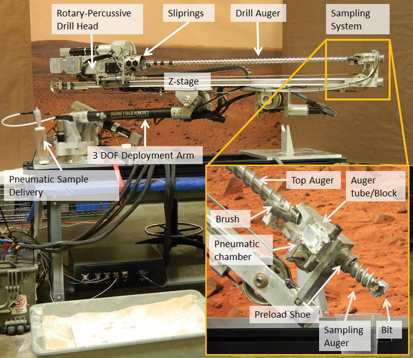
Components of the Icebreaker drill. The insert shows details of the sampling system. Color images available online at
4.4.1. Deployment boom
Icebreaker deploys from the spacecraft deck by way of a 3-DOF boom. This cantilevered boom enables the drill to reach multiple holes, avoid obstacles, and operate at an angle, if necessary. A camera on the lander deck would guide position of the drill. The boom needs to counteract the drill's Z-stage force with a preload approximately two times larger than the maximum allowable WOB. During the drilling operation, the Z-stage applies a WOB, pushing the drill downward but in turn raising the Z-stage, reducing the boom preload. For example, if the boom initially preloads the Z-stage with 200 N and the drill WOB reaches 80 N during the course of drilling, the net boom preload on the Z-axis will be reduced from 200 to 120 N. Once the boom preloads the Z-stage, no additional boom actuation is required during drilling operations. The drill is a stand-alone device. This split of functions simplifies surface operations and could also minimize control electronics. When the boom is not moving, the three motor controllers that govern the boom rotary actuators could be free to govern the drill actuators.
It should be noted that the ability of the drill to be deployed by a 3-DOF boom offers an alternative sample transfer option. The boom can lift the drill with a sample captured at the bit and position the end of the bit above the instrument inlet port. This option is described further in Section 6.3.
4.4.2. Z-stage
The Z-stage is the main structural member of the drill and is preloaded against the surface by a boom as shown in Fig. 9. The part that touches the ground, called the preload shoe, is made of a tube slightly larger than the bit diameter (hence, the auger and the bit could easily pass through). Its bottom edge contains sawtooth features to enable better grip on smooth surfaces. The preload shoe is part of an auger tube, which is a natural extension of a borehole. As cuttings move up the borehole to the surface, they continue to climb up until they reach the opening in the auger tube (see Section 6 for more details).
The drill head moves up and down the Z-stage via a carriage connected to a set of cables on both sides. Unlike prior drills such as the CRUX, which used a balldrive (i.e., a screw) to advance the drill head and in turn the auger drill, the Icebreaker drill uses cables and pulleys. This approach has several benefits. It is more dust tolerant than a ballscrew, it reduces vibrations from the drill head to the drill structure and in turn the spacecraft, and it is also much lighter. The two cables on either side of the carriage contain load cells. It is a differential from these two load cells that provides WOB feedback to the drill controller.
4.4.3. Drill head
The drill head is a two-actuator system—the first actuator rotates the auger while the second actuator drives the percussive mechanism. The percussive mechanism is based on a cam-spring principle. Voice coil and ultrasonic approaches were rejected because of the complex electronics required to drive them, relatively high ratio of the blow energy to system mass, potential thermal issues, and very low Technology Readiness Level (TRL) at the time of making the decision. Pneumatic and hydraulic systems were rejected because of very low TRL and added complexity required for fluid or gas management. A “dog clutch” was rejected because of low efficiency, heating due to sliding friction of two clutches against each other, and limited range of blow energy.
The cam-spring system was selected because it is robust, can be actuated by existing motors, offers relatively high energy per system mass, and has Apollo Lunar Surface Drill (ALSD) heritage. The main difference between the ALSD and Icebreaker is that the ALSD percussive mechanism was enclosed in a pressurized cylinder filled with nitrogen gas. This enabled lubrication and heat dissipation. Although the ALSD drill head leaked nitrogen gas when in vacuum, the leak rate was low enough to ensure successful operation on the Moon for at least 3 days (the duration of the Apollo surface mission). For Mars applications, such an approach would not work, since the drill head would lose all its nitrogen en route to Mars (a 7–9 month journey). For this reason, the mechanism has been redesigned with new materials and low friction coatings. The system has been thoroughly tested at Mars pressure conditions to evaluate its temperature and wear characteristics (Zacny et al., 2010b). To date, the cam-spring percussive system successfully completed over one million cycles at Mars pressure with no visible damage. This is equivalent to a continuous operation of over 8 hours, sufficient to drill eight, 1 m deep holes.
The drill head contains a six-channel slip ring that enables integration of sensors. The slip ring is used as a conduit for thermocouple wires to a temperature sensor embedded inside a drill bit, an optional downhole camera, and an optional regolith resistivity measurement sensor (see Section 4.4.4).
4.4.4. Drill auger
A single-string auger is made up of three parts as shown in Fig. 10: top auger, sampling auger, and drill bit. The shorter sampling auger is directly above the drill bit. Its flutes are 6 mm deep and 10° steep designed specifically for retaining cuttings. The long top auger, on the other hand, has 2 mm shallow and 30° steep flutes for preventing borehole collapse and for efficient movement of cuttings and fallback material out of the hole. It should be noted that this dual auger system has been specifically designed for the bite sampling approach, whereby the drill is periodically lifted out of the hole to deposit cuttings from the lower sampling auger. Although the sampling auger is not ideal for conveying of cuttings out of the hole, it is an effective way to retain sample from the bottom of the hole.

Triple-stage auger: top auger, sampling auger, and drill bit. The bit has tungsten carbide cutters and an embedded temperature sensor. The sampling auger captures and retains the cuttings while the top auger efficiently moves cuttings and fallback material out of the hole.
The Icebreaker drill auger is required to move ice chips to the surface, where they can be delivered to science instruments. Augers work very well if the friction coefficient between auger material and cuttings is much lower than the friction coefficient between the same cuttings and the borehole wall (Zacny and Cooper, 2007c). The friction between ice chips and aluminum or steel (some of the candidate materials for the Icebreaker drill string) increases by at least a factor of 5 as temperature falls from near zero to -65°C (Talalay, personal communication, May 26, 2013). At these low temperatures, friction of ice on ice is lower than friction of ice on steel or aluminum (Schulson and Fortt, 2012). Hence, it is expected that the auger will not move ice chips to the surface as well at low temperatures on Mars. The bite sampling approach compensates for the effect of the high friction coefficient on auger conveyance.
The auger has a diameter of approximately 25 mm. This particular size was selected as a compromise between two conflicting requirements: drilling energy/WOB and sample volume. In general, drilling energy and WOB decrease as auger diameter gets smaller. However, auger strength and stiffness as well as sample volume increase as diameter gets larger.
The hollow auger allows the wires for the bit temperature sensor, the downhole conductivity sensor, and the downhole camera to pass through. A heat pipe could also be integrated into a hollow auger. The pipe could transfer heat generated during the drilling process at the bit to the section above the surface. Alternatively, a long heater could be embedded inside the auger, or resistive heater patterns could be deposited directly onto the outside of the auger (see
4.4.5. Drill bit
The drill bit design as shown in Fig. 11 has been specifically designed to perform well in ice and icy soil (i.e., cutters are placed at zero rake angle) and also in hard, competent rocks (cutter tips are slightly rounded off so as not to break during hammer drilling). The drill bit includes borehole reamers—these are additional cutters pointed upward to help the drill during retraction from the borehole in case of borehole collapse or rock inclusions.
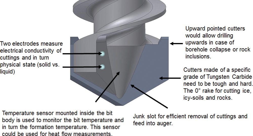
Icebreaker tungsten carbide drill bit. Color images available online at
The drill bit uses tungsten carbide cutters to efficiently break the rock. The carbide cutters have been selected based on a compromise between hardness and toughness. Hardness is required to avoid premature cutter wear when drilling hard and abrasive materials. Toughness is required to prevent cutter fractures when the percussive system is employed in hard rocks.
The cutter rake and side rake angle were designed to reduce drilling torque and to sweep the drilled cuttings to the strategically placed junk slots. Junk slots that are incorrectly designed or placed can substantially increase drilling torque, temperature of the bit and the formation, and in extreme cases even halt the drill advancement entirely. The Icebreaker junk slots are conduits for cuttings movement from the bottom of the hole and into the auger and hence are critical to the bottom hole cleaning process and in turn efficient and cool drilling.
The drill bit also has an embedded temperature sensor. The sensor allows continuous monitoring of the thermal environment around the drill bit. This is a critical telemetry that is used as input in the drilling algorithm to prevent possible warming of the sample. The thermal data, along with drilling telemetry such as power and penetration rate, are used to evaluate drilling efficiency (Zacny et al., 2008; Szwarc et al., 2012). Temperature data are especially critical when drilling icy formations. In that case, the temperature sensor is used to estimate the temperature of the surrounding ice. If the ice temperature gets close to melting, the following three actions could be done: (1) drill rotational speed can be reduced; (2) the drilling can be stopped altogether, the bit retracted 1 cm above the bottom hole, and the auger slowly rotated; (3) the drill can be completely pulled out of the hole until the borehole cools down.
Because martian soils have clay minerals and salts, the soils can be partially or fully thawed at temperatures below 0°C. Chevrier et al. (2009) determined theoretical eutectic values for sodium and magnesium perchlorate solutions as potential liquid brines at the Phoenix landing site to be 236±1 K for 52 wt % sodium perchlorate and 206±1 K for 44.0 wt % magnesium perchlorate.
The electrical conductivity of regolith depends on many properties such as the degree of saturation, porosity, composition (conductivity) of the pore water if present, mineralogy (fraction of charged particles), salt content, and temperature (Mitchell, 1992). Since the electrical conductivity will largely depend on the mobility of ions and in turn on the fraction of unfrozen water content, measuring conductivity will enable determination of the physical state of the material (liquid or solid). Measuring resistance (inverse of conductivity) will no doubt give a much better indication of the regolith physical state than measuring its temperature. This is because the temperature at which regolith becomes sticky or soft might vary depending on many factors such as ion concentration and water saturation. A more direct indication of the change in physical state (solid–liquid) is a change in the formation's electrical resistance. An optional soil resistivity measurement sensor may be fitted into the drill bit.
Clay-rich regolith exhibits three regimes: low conductivity (<− 6°C), transition (−6°C to −3°C), and high conductivity (>−3°C) (Zacny and Cooper, 2005). Hence, identifying the transition zone where regolith starts to thaw would be of paramount importance (this is because the regolith thaws at −6°C and not 0°C). If the drilling software is set up to slow down drilling at 0°C (or just below) and not at −6°C, the drill might freeze in the hole.
To measure the resistance of the cuttings during drilling, two electrical prongs can be embedded inside the bit in such a way as to protrude slightly below the bit shank as shown in Fig. 12 (note that the drill in Fig. 12 is an old prototype bit and is not used in the Icebreaker system). Figure 13 shows the temperature and resistance of clayey regolith during a drilling test. The resistance at a bit temperature of −5°C, −4°C, and −2°C was 1 MΩ, 300 kΩ, and 150 kΩ, respectively. At the onset of drilling and when the bit was pulled out of the hole after the test, the resistance was too large to measure (>40 MΩ). The rate of resistance decrease per degree Celsius was 700 kΩ (-5°C to −4°C) and 75 kΩ (-4°C to −2°C). This indicates that ion mobility was sharply increasing as the temperature was approaching 0°C. This test validated the resistivity measurement approach as a viable method to be employed in future planetary drills to monitor the state of the drilled material during the drilling process.
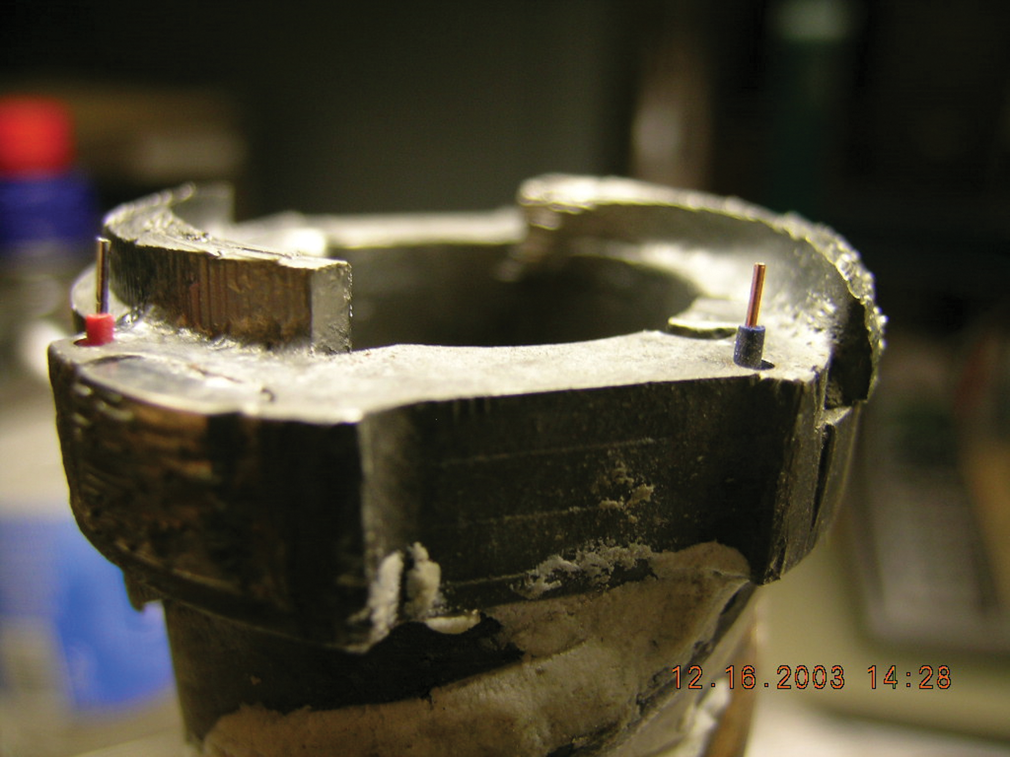
A diamond-impregnated drill bit with two electrodes sticking out. The electrodes are used to measure resistance of the cuttings during drilling and in turn infer their physical state (frozen or thawed). Color images available online at

Electrical resistance and the drill bit temperature during drilling in clayey soil. (Zacny and Cooper, 2005).
It might be feasible for pockets of brines to be present in subsurface ice. In fact, in the Siberian Arctic there are lenses of sodium-chloride water brines (called cryopegs) that have constant temperatures in the range of −9°C to −11°C. These cryopegs are sandwiched within permafrost marine sediments that are 100–120 thousand years old (Gilichinsky et al., 2003). A number of bacteria were isolated from these cryopegs that exhibited the ability to survive and develop under harsh conditions, such as subzero temperatures and high salinity (Shcherbakova et al., 2004). This resistivity approach will identify such a condition and trigger software to pull the drill out of the hole immediately, to prevent freezing the drill in place.
In addition, Fletcher (1968, 1970) predicted the existence of a quasi-liquid surface within about −6°C to −1°C, with thickness of a few molecular layers, increasing to about 10 layers at −1°C. Although these results, based on free energy calculations, are speculative, they do fit a similar temperature profile observed in formations containing clay minerals.
4.4.6. Brushing station
The brushing station uses a passive brush with long steel bristles to “scrape” drilled cuttings off the auger flutes (Fig. 9). The brush wheel forms a worm-gear configuration with the auger. Hence, as long as the auger rotates, so does the brush. If space is limited, a linear brush could be used instead. The brush is also used to clean the auger before it is inserted back into the hole to minimize cross contamination. Since the brush is in direct contact with the drill, it will have to be sterilized and stored inside a biobarrier.
4.5. Drilling software
Before actual drilling commences, the drill will need to be deployed from its stowed and locked horizontal position. Once deployed, the drill will have the following modes of operation: (1) Idle: All motors are standing idle awaiting commands. (2) Warm-up: Heaters are activated (if required) to warm the motors up to a temperature where they are safe to operate. (3) Seek: The drill searches for the ground level or the bottom of the hole. This operating mode accounts for potential fallback of material into the hole to protect against stalls and potential corkscrewing. During this step, the bit temperature would measure subsurface temperature. (4) Drill: The drill penetrates the subsurface in short increments called bites, with all necessary automated safety checks and fault recovery procedures. In addition, temperature and potentially formation electrical resistivity data are acquired and analyzed in real time. (5) Retract: The drill retracts from the hole. (6) Sample transfer: The sample is transferred into an instrument. There are three options as described in Section 5.
The first steps that lead to preloading of the drill structure against the surface are relatively easy to accomplish and hence will not be dealt with in this paper. However, the actual drilling processes (Seek, Drill, Retract, etc.) require development of robust software and implementation of low-risk drilling protocols. This section describes the drilling software.
Large communication delays between Earth and Mars (up to 12 hours) justify robust drilling algorithms and protocols. If the drilling system relies entirely on software to make decisions and continues drilling as fast as possible without retracting the auger out of the hole, there is a risk that the software will not be able to deal with all drilling conditions. As a consequence, the drill could get damaged or permanently stuck and prematurely end the mission. An alternative approach is to limit the drilling software to a set of well-defined subroutines. Here, any anomaly, however small, would require the drill to be pulled out of the hole and remain in its “home” position for further commands from Earth. This approach lowers drilling risk at the expense of drilling speed and energy.
The first approach has been developed by NASA Ames Research Center while the second approach has been tackled by Honeybee Robotics. Most probably, the final Icebreaker software will be a compromise between the two approaches; however, for now these two approaches are being pursued in parallel.
The NASA Ames software includes diagnostic software for monitoring the state of the drill, and contingent execution software for guiding the drill through a daily drilling plan while at the same time helping the drill recover from off-nominal situations (Glass et al., 2005, 2011). The software has been undergoing extensive field testing in the Arctic, the Antarctic Dry Valleys, and in a Mars environmental chamber. The Honeybee Robotics approach is divided into mission-critical and mission-noncritical routines. Critical routines deal with the conditions that would lead to the end of the mission, while noncritical routines deal with drilling optimization during nominal conditions.
In both cases, the software relies on drill telemetry to infer the state of the drill and to control the drill operation via rule-based and model-based algorithms and subroutines. If an off-normal condition is detected, in all cases the drill is required to go back to its safety mode (retracts from the hole and empties the auger by moving the auger past the brush) and awaits further instructions from mission control.
4.5.1. Mission-critical events
Mission-critical events are those events that could lead to a mission failure (e.g., drill stuck in the hole). To avoid them, the Icebreaker drill relies on its robust drilling software and drilling protocols. In general, the two environments that should be considered are formations with ice and without ice. The next sections describe various events that could occur in both of these environments. It should be noted that, although only some of the events described below were observed either in the field, in a lab testing, or in the Mars chamber testing, all the incidents could in fact occur on Mars. It needs to be emphasized, though, that in some cases, it might also be difficult to determine what type of event occurred since two or more events may result in the same outcome (e.g., drill stuck).
4.5.1.1. Formation containing ice
If a formation contains ice, there are several conditions that can occur that would prematurely end the mission. These conditions include drill freeze in a hole, bit icing, auger flutes icing up, and drill choked up with cuttings.
If drilling is aggressive (uses a lot of power), the ice occurs near the surface, and atmospheric pressure is near the triple point of water, it is possible that the energy released during the drilling process as heat is used up almost entirely by the latent heat of fusion plus vaporization. As ice turns into vapor, it not only uses up all the heat generated during the drilling process (and this in turn keeps the borehole and the drill bit at the freezing point or below) but also blows the cuttings out of the hole (Zacny et al., 2004). This scenario, however, only occurs if the drill starts drilling aggressively right from the beginning and cuttings are constantly cleared out of the hole. If for some reason sublimation stops and cuttings fill the auger flutes, restarting this process will be almost impossible. Water vapor forming near the rotating drill bit will create a pressure-cooker effect; that is, the vapor pressure will increase above the triple point, which leads to vapor changing its state to liquid. That water would be thermodynamically unstable and could revert to ice. This scenario may also occur if icy regolith or ice is covered by a thick layer of dry regolith. That regolith will form a tight restriction and prevent any water vapor from escaping explosively out of the hole. There are a number of possible outcomes, and each of them has been observed during laboratory and field tests.
In the first instance, the ice can stick to the drill bit and prevent cutters from biting into the formation and cease penetration (see Fig. 14). Although the drill would not be stuck, further progress would be stopped. The drill would have to be pulled out of the hole and the ice allowed to sublime away. Pointing the drill bit toward the Sun would speed up the process (see Fig. 15). Ice sublimation on Mars is not a fast process but was observed by the Phoenix mission in the trench informally called “Dodo-Goldilocks” over the course of 4 days (Mellon et al., 2009).
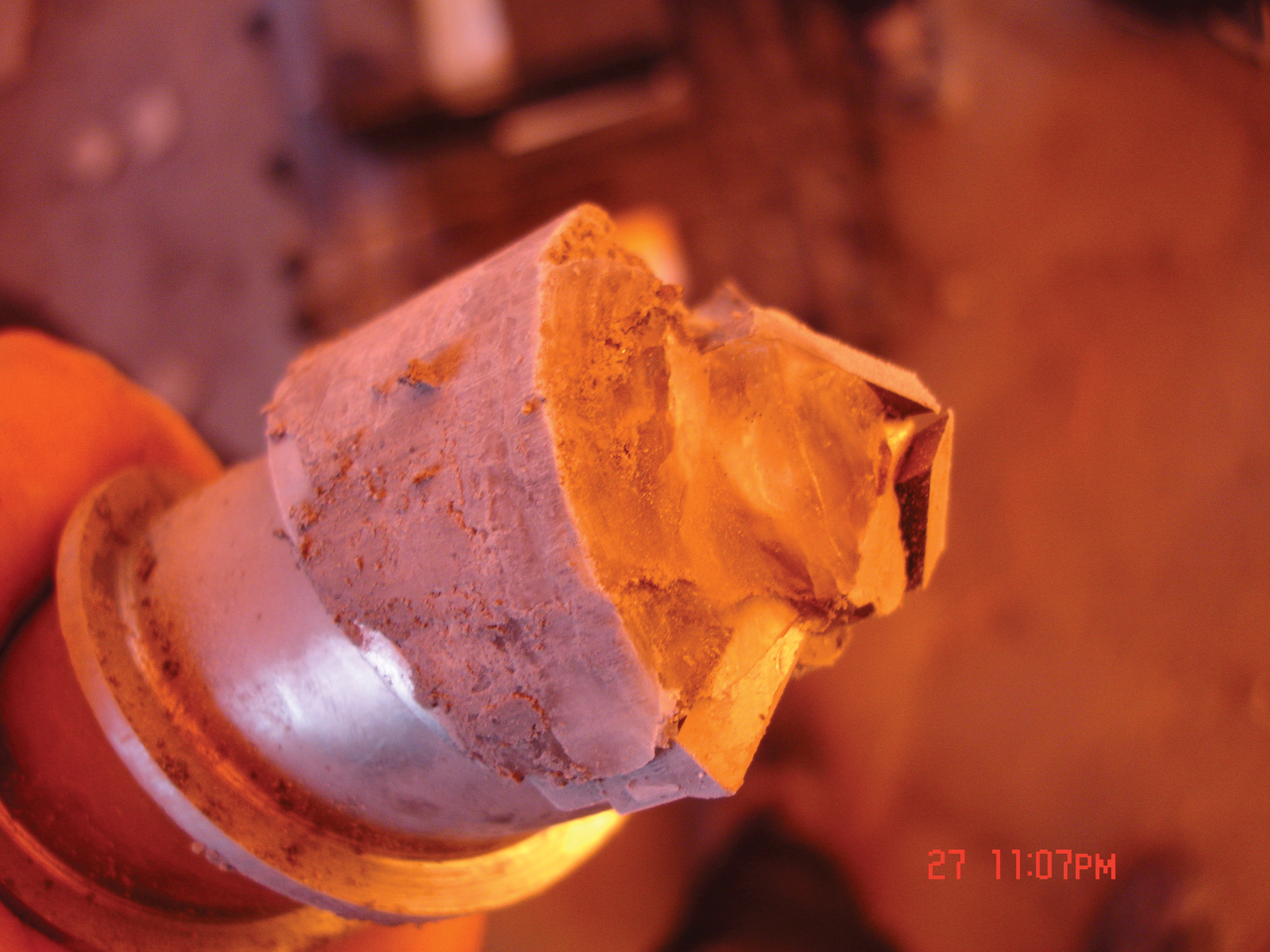
Ice at the bottom of the hole could thaw and refreeze around the cutters, thereby stalling penetration rate. Color images available online at

The boom can point a drill toward the Sun to speed up de-icing via sublimation. Color images available online at
In the second scenario, the ice could refreeze within the cuttings. These cuttings could be augered out of the hole and dumped onto the ground. This scenario would not be mission-ending, but the sample would most likely be lost since large chunks of regolith would be impossible to deliver to an instrument. Regolith clumping was observed during the Phoenix mission (Arvidson et al., 2009). In this case, regolith that might have had some water ice and perchlorate salts became sticky and formed clumps that did not pass easily through a screen above instruments' inlet ports. It was observed that regolith on the sunlit side of a scoop stuck to the scoop, while regolith on the shadowed side successfully fell out of the scoop onto the screens (Fig. 16). Hence, granular, loose sample can be maintained by keeping the formation and the sample as cold as possible.
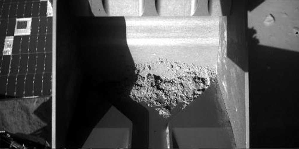
Mars Phoenix's scoop after it had been inverted and vibrated to jar the sample of icy soil loose. The image shows that much of the sample was clumpy and remained stuck inside the scoop. Credit: NASA.
In the third scenario, ice can also form between the auger surface and the cuttings; that is, icy cuttings would stick to the auger surface and would not move up the auger (see Fig. 17). This condition is serious because further conveyance of cuttings from the part of the hole below the restriction would not be possible. In this case, the penetration rate would drop, which would trigger an increase in WOB. The torque would also increase since the cuttings below the restrictions would be pushing against the borehole and the auger at the same time, causing the auger to slow down (this is referred to as choking). If this event is identified fast enough by the drilling algorithm, the drill should be immediately pulled out of the hole. As before, if the auger is exposed to the Sun, the ice could sublime away while regolith would either gravity fall or could be brushed off with a passive brush, which is part of the sample delivery system within the Icebreaker drill.
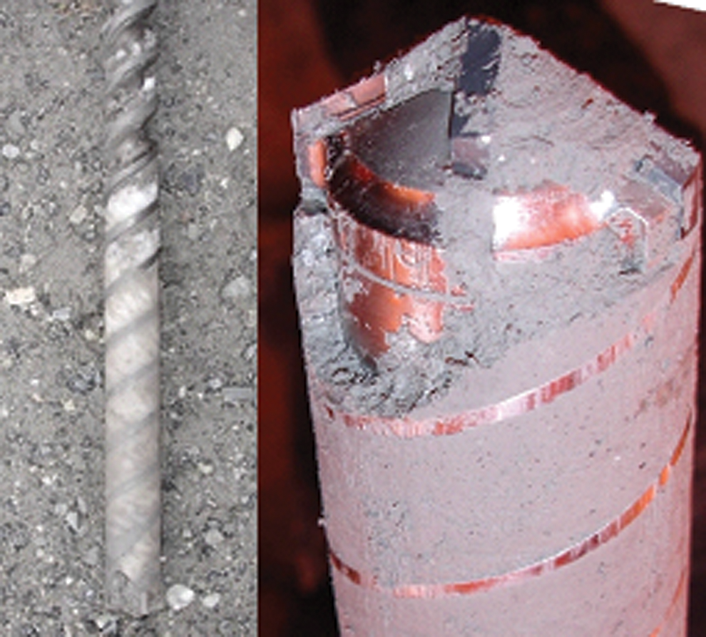
Ice (left) and icy soil (right) refroze within the auger flutes. Color images available online at
The fourth scenario pertains to liquid water freezing the cuttings and freezing onto the borehole. Hence, the borehole turns into a nut, while the drill is a screw (Fig. 18). This scenario could occur if the auger surface is coated by a non-stick coating. The drill could potentially be moved a little bit up or down (and this has been observed), but screwing the drill out of the hole entirely is prevented by the sample-retaining auger of the Icebreaker drill and could never be achieved. This is because the lower flutes are designed to retain sample, not to transport it upward along the flutes as the top section of the auger does.
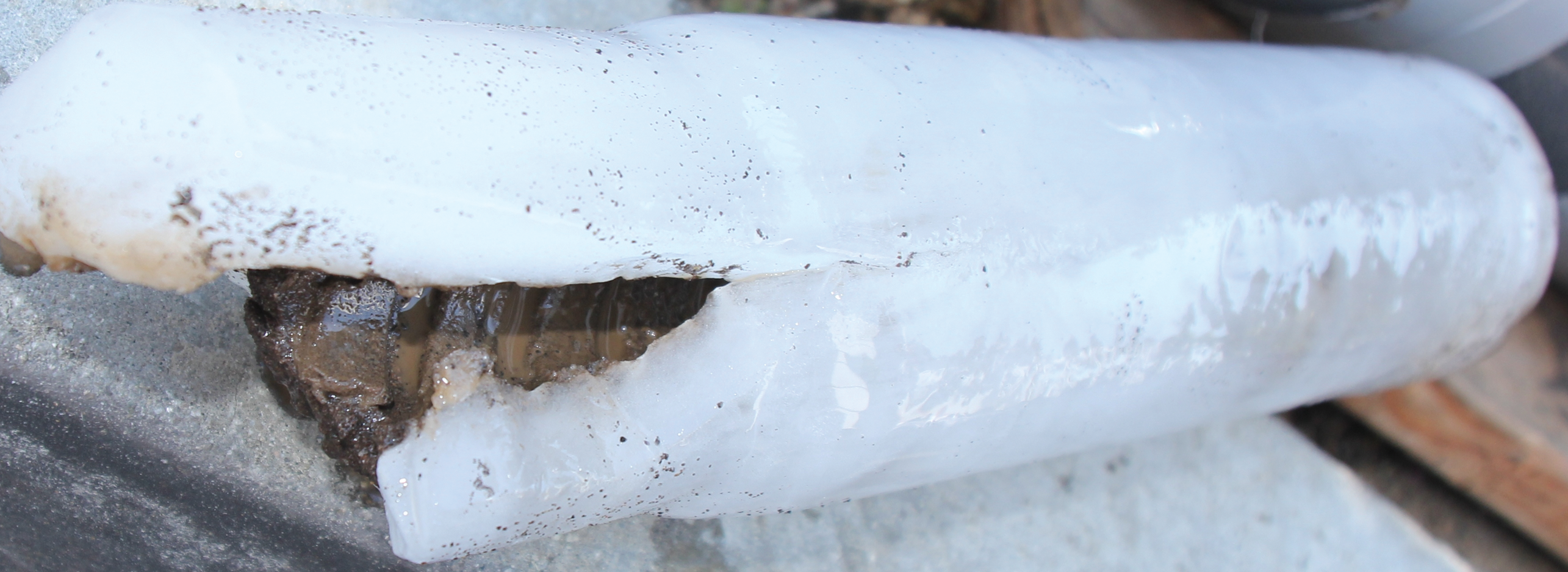
The grooves in icy soil are an impression of auger flutes. Color images available online at
If this occurs, whether the drill would have the capacity to recover or not depends on the strength of the formation (i.e., water content and temperature) and on the drill power (rotary and percussive). Trying to get the drill out of the hole would be essentially like trying to get a rebar out of concrete. This is in fact a good analogy, since the strength of frozen regolith is as high as or even higher than the strength of concrete (Zacny et al., 2007). It might be possible for the powerful drill to deliver enough torque and percussive energy to shear away the iced-up “thread,” but this approach may not work in most, if not all, cases. In the most likely scenario, the drill would never be recovered.
In the fifth scenario, the water ice can freeze within the cuttings and bind onto the borehole and the auger. This is the worst case, and such an event would most likely permanently trap the drill in a hole. Such occurrences are common in the polar regions. Figure 19 shows a set of tools that were used to recover a stuck drill (bottom of the picture) in the Antarctic Dry Valleys. It took two people over 6 hours to get the frozen drill out of the hole. It should be noted that any of the four previous conditions could lead to the fifth one (i.e., drill frozen in a hole).
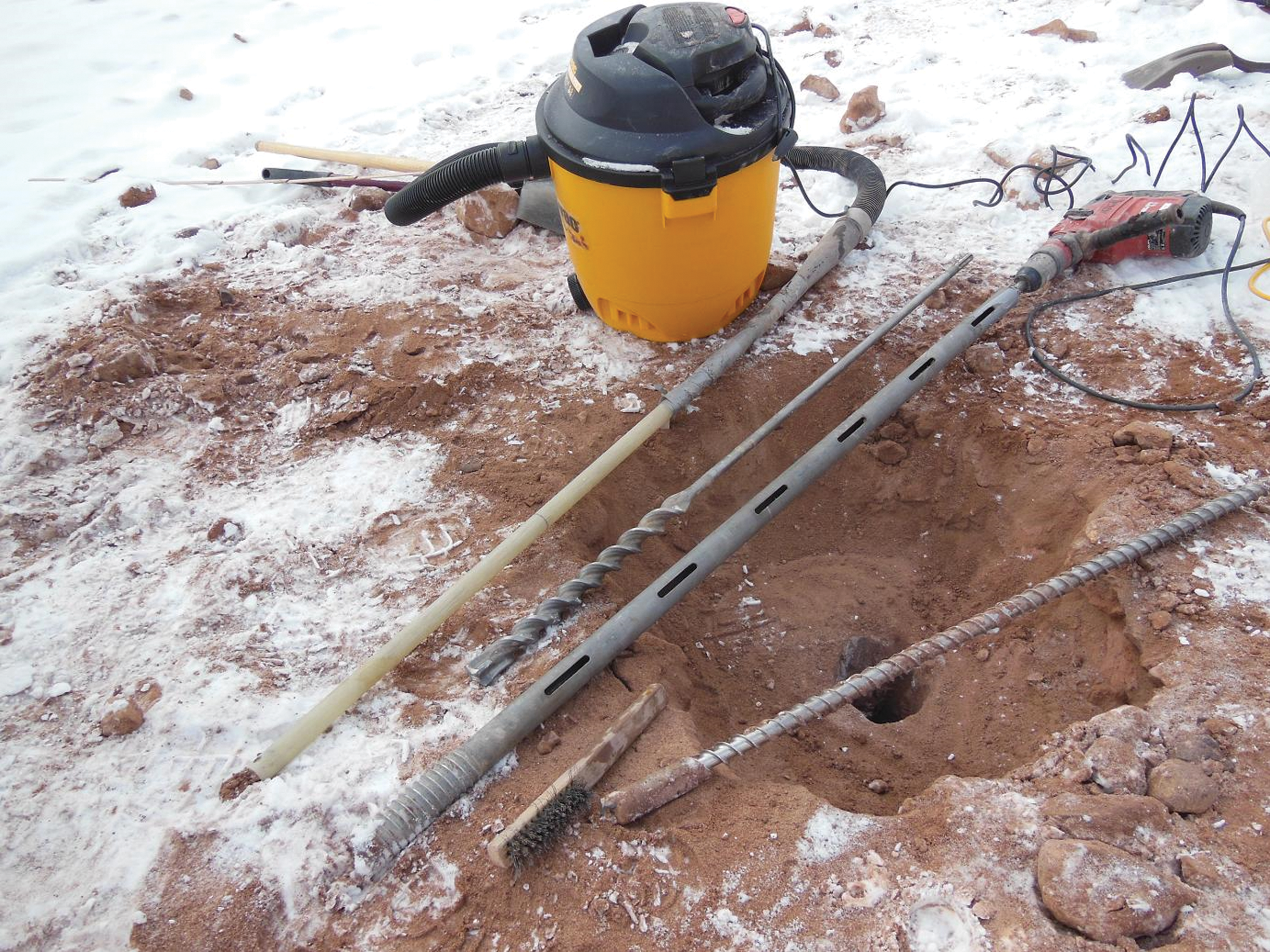
A set of tools used to recover a stuck drill: a vacuum for moving frozen chips out of the hole, a long drill for over-drilling around the stuck drill string, a long corer for drilling over the stuck drill string, and a brush. Color images available online at
If a drill freezes in a hole on Mars, the only way out is to warm up the drill string and melt the ice. Assuming a 1 m long and 25 mm diameter drill is stuck in ice at −55°C and has a thermal conductivity of 2.5 W/mK, the power required to reach 0°C at the surface of the auger (i.e., melt ice sticking to the surface of the auger) would be approximately 300 W and take ∼24 minutes (Fig. 20). This is a theoretical approximation, and tests would have to be conducted to determine the actual power and time required (and in turn required energy). This contingency plan would require integration of a line heater inside the auger capable of withstanding the hammering action of the drill.
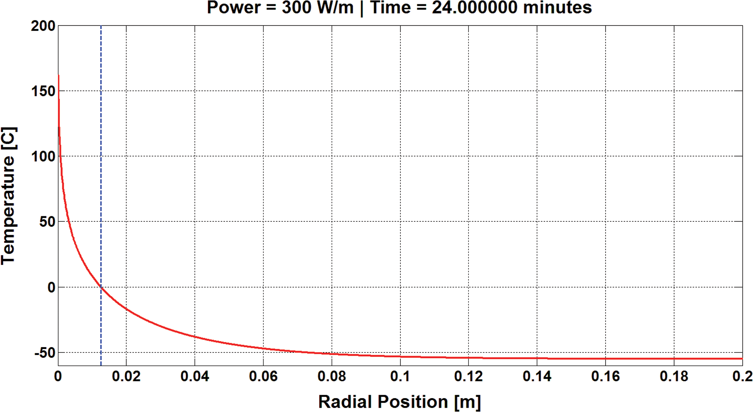
Temperature of a 25 mm drill string frozen in a −55°C ice, being heated by a 300 W integrated line heater. The radial position is measured from the center of the drill string. The vertical line at 0.012 m represents the auger surface. Color images available online at
To prevent any of the above conditions from occurring, the drill bit has an integrated thermocouple for monitoring the bit temperature. The temperature data are then fed into a drilling algorithm that monitors the absolute temperature and the temperature increase. If the temperature starts rapidly rising or rises slowly but approaches the upper bound of the temperature limit (currently set at 0°C), the drilling software reduces rotational speed and lowers WOB. If this does not result in a drop in temperature, the drill is lifted off the hole bottom (i.e., WOB is zero) while the auger is rotated at slow rpm. If the temperature drop is still not satisfactory, the final step would be to pull the drill out of the hole and allow the subsurface to cool down.
If a formation contains clay minerals or salts, temperature alone cannot be used to infer physical state of ice. This is because brines can form at a temperature much lower than 0°C. Clayey regoliths also exhibit freezing point depression. The only certain method of determining the onset of water ice changing phase to liquid is to continually measure the cuttings' conductivity. This method is described in Section 4.4.4.
4.5.1.2. Dry formation (no water ice present)
In formations that have no ice (dry formations), the biggest problems include an auger choked up with cuttings or fallback material (hole collapse) and loose pebbles either within a borehole wall (leading to a binding fault) or at the bottom of the hole.
Choking may occur because the auger has not been designed properly to efficiently move the cuttings to the surface, or the auger is not rotated at high enough rotational velocity, or the drill bit has poorly located junk slots. The choking due to borehole collapse is much more difficult to deal with. In both cases, having a more powerful rotary motor with ample torque might be enough to recover the drill. However, a better approach is to implement a drilling protocol that would keep the hole open by frequent reaming. This will not require cuttings to be moved along the entire length of the auger. The bite sampling approach solves the auger-choking problem by implementing both solutions. This approach is similar to peck drilling in machining process, where a drill bit is periodically removed to clear metal shavings. Since the drill is moved down and up several times, it reams the hole, which reduces the chances of it getting stuck and helps reduce parasitic losses due to auger flutes rubbing against the borehole.
If a rock is protruding from the borehole wall and causing a binding fault (this will be identified by a torque spike occurring two times per revolution for two-flute augers), it might be possible to try to ream through this area. However, if a rock is relatively small, it might completely dislodge and either fall to the bottom of the hole or continue rubbing against the auger. Unfortunately, there is no robust method to deal with loose rocks. It might be possible to try to drill through them to reach more consolidated formation; however, this could cause cutter fractures due to the impact of cutters on loose rocks.
4.5.2. Mission-noncritical events
The mission noncritical drilling aspects pertain to optimizing drilling parameters to minimize drilling specific energy. Specific energy is the energy required to drill a unit depth of the hole. This term takes into account power and penetration rate. Hence, for example, the more efficient drill will require 100 Whr to drill to 1 m depth, while the less efficient drill will need 200 Whr. It is worth pointing out that minimizing drilling specific energy also helps reduce the mission-critical events in icy formations, since less heat is being generated per depth of the hole.
For the Icebreaker system, the software uses a so-called “energy routine.” In this rule-based routine, the drilling proceeds in rotary mode as long as a penetration rate above 10 cm/hr is being maintained for WOB<40 N. If the penetration rate drops and maintaining it would require increasing WOB to above 40 N, the percussive actuator is engaged. The percussive system increases the penetration rate but at the expense of higher power. In soft rocks and regolith, high penetration rate can be achieved with rotary drilling alone. However, in harder formations, percussive mechanisms need to be engaged.
4.6. Drill as a science instrument
The primary purpose of the drill is to provide samples for the science instruments. The drill, however, could also be used to augment the instrument data with information about formation strength and temperature.
In particular, the drill bit includes an integrated sensor for monitoring temperature during drilling operations. Initially, when the drill is lowered to the ground for the first time, the bit could be used to obtain the temperature of the ground. That temperature is used as a reference point and to calibrate the thermal model for the drilling algorithm. Every subsequent time the drill is lowered into the hole to take another “bite,” it could acquire a borehole ambient temperature at different depths. These single data points could then be plotted as a function of depth to reveal a thermal gradient. The thermal gradient combined with an estimate of formation thermal conductivity could then be used to determine heat flow properties of Mars.
Many researchers have already demonstrated that drilling telemetry such as power, penetration rate, and WOB could be used to infer formation strength and in particular unconfined compressive strength or UCS (Teale, 1965; Mellor, 1972; Reddish and Yasar, 1996; Zacny et al., 2006; Paulsen et al., 2010). In addition, Mellor (1971) demonstrated that UCS increases with an increase in water-ice content (peaking at maximum saturation) and with a decrease in temperature (peaking at approximately −80°C). The strength of pure ice also increases with a decrease in temperature, reaching 70 MPa at -100°C (Tsytovich, 1975). Hence, by estimating UCS from the drilling data and combining it with measured subsurface temperature data, it is possible to determine the fraction of ice in the formation. Once the fraction of ice and the ice temperature are known, a thermal conductivity estimate could be narrowed down.
Because the total drilling power is a sum of power required to break the formation, convey the cuttings up the flutes, and overcome parasitic losses due to auger rubbing against a borehole, the determination of formation strength can only be done initially with each hole, when the flutes are empty. Parasitic losses could be measured (and in turn factored out) by rotating the auger in a hole ∼1 cm above the bottom of the hole (i.e., making sure no drilling takes place). Once the drill starts drilling, it will be more difficult to infer formation strength due to the added contribution to the total power from the auger conveying the cuttings.
5. Sample Acquisition
There are two possible cuttings acquisition approaches. In the first one, the drill can continually drill down to its target depth while another sample delivery system transfers the cuttings to appropriate instruments as soon as they reach the surface. This approach has a major drawback in that the auger torque due to cuttings being augered to the surface would become higher with depth. In addition, the material that appears on the surface would not represent the current maximum depth but rather a shallower depth. In a 1 m long and 25 mm diameter auger that has 2 mm deep flutes, the volume occupied within the flutes is 144 cm3. Assuming a fluff factor of 2 (i.e., volume of cuttings is twice as large as volume of originally compacted and consolidated material), the initial volume of the sample occupying the 144 cm3 is 72 cm3. Since the auger diameter is 25 mm, the depth of hole with that 72 cm3 volume is 15 cm. Therefore, material on the surface once the drill reaches 1 m depth represents a depth of 85 cm (and not 1 m). To recover those additional samples, the drill has to be retracted out of the hole, and material on the flutes that represents the bottom 15 cm formation must be scraped away into a sample transfer system.
The alternative to drilling to the maximum depth in one go is to employ a peck drilling approach, referred to as “bite” drilling. In this approach, the drill is periodically retracted from the hole, the cuttings are transferred to an instrument, and the drill is lowered back into the hole to acquire the next bite as shown in Fig. 21. This approach requires the lower section of the auger to have deep flutes to accommodate as much sample as possible and also flutes at a shallow angle to retain as much sample as possible.
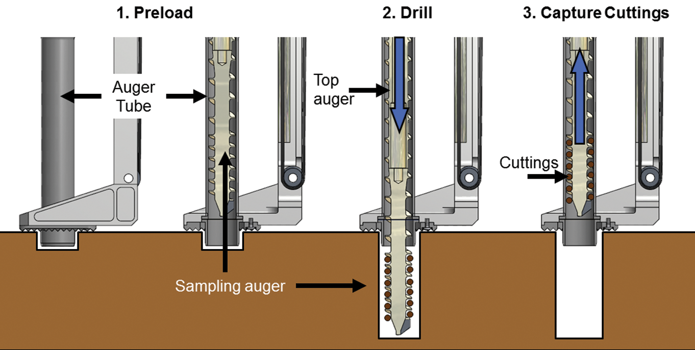
The “bite” sampling approach. Color images available online at
It should be noted that, if for some reason the hole collapses while the drill is retracted, the next time the drill is lowered back into the hole, the fallback material will be augered out first; then the new material will be acquired on the sampling auger. Hence, there is no danger in sampling the same material twice.
This bite sampling approach has several advantages. For example: • The stratigraphy is more likely to be preserved since samples are delivered from known depths. However, the degree of “stratigraphy preservation” will largely depend on the properties of the subsurface such as porosity and, in the case of regolith, also a regolith cohesion and friction angle. It should be emphasized, though, that there will always be some uncertainty regarding the depth from which any given sample is obtained. The best that can be said is that if some new material appears, then it must have come from the newly drilled interval. However, materials previously observed may not still be present at the bottom of the hole even if they are found in the cuttings (since they may have fallen in from higher up). Bite sampling does, however, help. • The drill power to reach 1 m is lower since there is minimal drag due to cuttings being augered to the surface (cuttings are captured in the lower “sampling” auger and do not climb up the flutes to the surface). • If desirable, samples from a target depth can be delivered while the rest can be discarded onto the ground. • Periodically removing the drill from the hole also allows the subsurface and the drill itself to cool down. This cooling period is critical since the biggest danger in drilling ice-rich regolith is thawing followed by refreezing of the ice around the drill. • The method also offers “graceful failure,” in that unless the drill breaks before acquiring its first sample, the system will always be able to deliver some sample for analysis. • Finally, every time the drill is lowered back into the hole, the borehole temperature would represent the ambient subsurface temperature. Adding up these temperature data can reveal the thermal gradient and in turn heat flow properties of Mars, if thermal conductivity is known. It should be pointed out that in order to measure the temperature of the hole wall on reentry the drill stem would need to thermally equilibrate, and this could take some time. In addition, because the drill auger will be made out of some metal, and metals are inherently good conductors, a thermal gradient will exist between the top of the auger above the ground level and the tip of the auger touching the bottom of the hole. The effect of this thermal gradient would also have to be taken into account.
It should be noted that there is going to be some level of cross contamination due to the smearing of cuttings on the flutes against the borehole as the auger is being pulled out. The extent of cross contamination will depend on the cuttings' frictional and cohesive properties.
6. Sample Delivery
To reduce the risk related to sample delivery, the Icebreaker drill enables a triple redundant sample delivery system compatible with a bite sampling approach. These include a scoop mounted at the end of a 5-DOF robotic arm, pneumatic transfer, and a 3-DOF deployment arm. The last two sampling systems may be viewed in a YouTube video (Honeybee Robotics, 2012).
6.1. Five-DOF sampling arm and a scoop
The scoop is the most straightforward method of delivering a sample and has Mars Viking 1 and 2, Mars Phoenix, and MSL heritage. Since the Icebreaker mission may have to deal with sticky material, the scoop has been designed with an integrated scraper and resembles an ice cream scoop (Davé et al., 2012). The scoop is deployed by a 5-DOF arm. When the sample is ready for transfer, the scoop is positioned next to the sample drop-off point as shown in Fig. 22. It can retrieve samples during drilling, drill retraction, and from the shallow-angle flutes as the end of the auger is brought up. After the scoop has been filled with a sample, the arm moves the scoop and positions it above an instrument inlet port. The scoop scraper blade is connected to a lever, and to discharge the sticky sample the lever has to be moved through 90°. To achieve that, the arm preloads the lever against a hard stop just above the sample inlet point and then moves the scoop forward. This forward motion of the arm/scoop holds the blade in place and scrapes the sample into the instrument. The implementation of the scoop offers sampling redundancy. If for some reason the drill fails, the scoop could be used to acquire surface material for analysis.
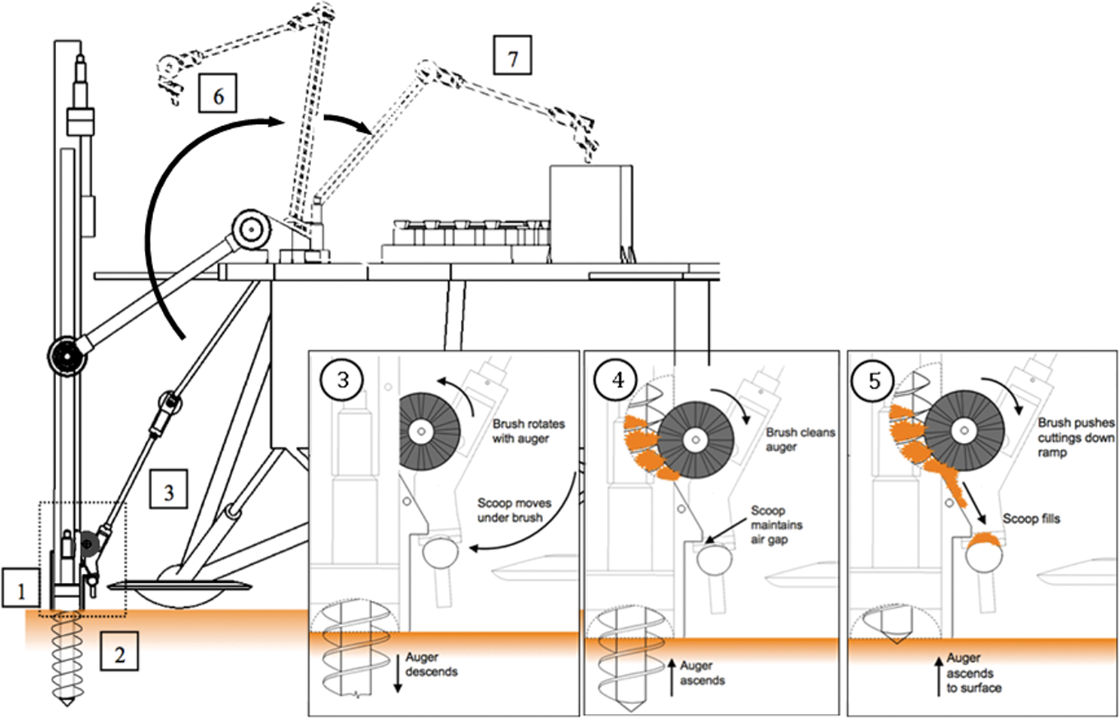
Diagram stepping through the sample acquisition and delivery operation (Davé et al., 2013). Color images available online at
The scoop has been tested in the Mars analogs of the Canadian High Arctic and the Dry Valleys of Antarctica. In addition, the scoop has been tested in a Mars environmental chamber and delivered a variety of materials, ranging from noncohesive to highly cohesive, that is, sticky (Davé et al., 2013).
6.2. Pneumatic sample transfer
Gas is a very effective medium for lofting particles in a vacuum (Zacny et al., 2005). In the best-case scenario, 1 g of gas could lift close to 6000 g of regolith at velocities approaching 10 m/s in tests conducted at Mars pressures (Zacny et al., 2010c, 2010d). Such high efficiencies are possible because gas exit velocity in a vacuum is proportional to pressure ratio rather than pressure difference. Of course, if the mission requires capturing a subsurface sample, the drill system would have to include some kind of cuttings catchment subsystem or use reverse circulation drilling.
The low atmosphere not only makes air drilling possible but also allows implementation of a pneumatic sample transfer. Pneumatic sample transfer is a point-to-point sample delivery method (Fig. 23). The sample is first acquired into a small chamber while the door is in the open position. Once the chamber is full (this could be triggered by an optical sensor inside the chamber), the door closes. A puff of gas is then directed into the chamber on one side, and the gas with the content of the chamber (i.e., the sample) is moved through the sample delivery tube and directly into a cyclone separator. The sample drops to the bottom of the sample delivery hopper, while the gas escapes to the atmosphere from the top of the cyclone separator. A hopper could then distribute the sample via a carousel underneath it to various instruments or deliver a sample to a sample-processing system such as a crusher (Zacny et al., 2012b). Alternatively, the pneumatic system could contain several cyclone separators, each one mounted above the instrument inlet port. A gas manifold would then direct the dusty gas to the appropriate port. In each case, an additional couple of gas puffs could be used to clean up the sample delivery hardware to prevent cross contamination before the new sample is acquired. This sample delivery approach has been tested at 760 torr while drilling Indiana limestone (Fig. 23) and inside a Mars chamber while drilling ice-cemented materials (Fig. 24).
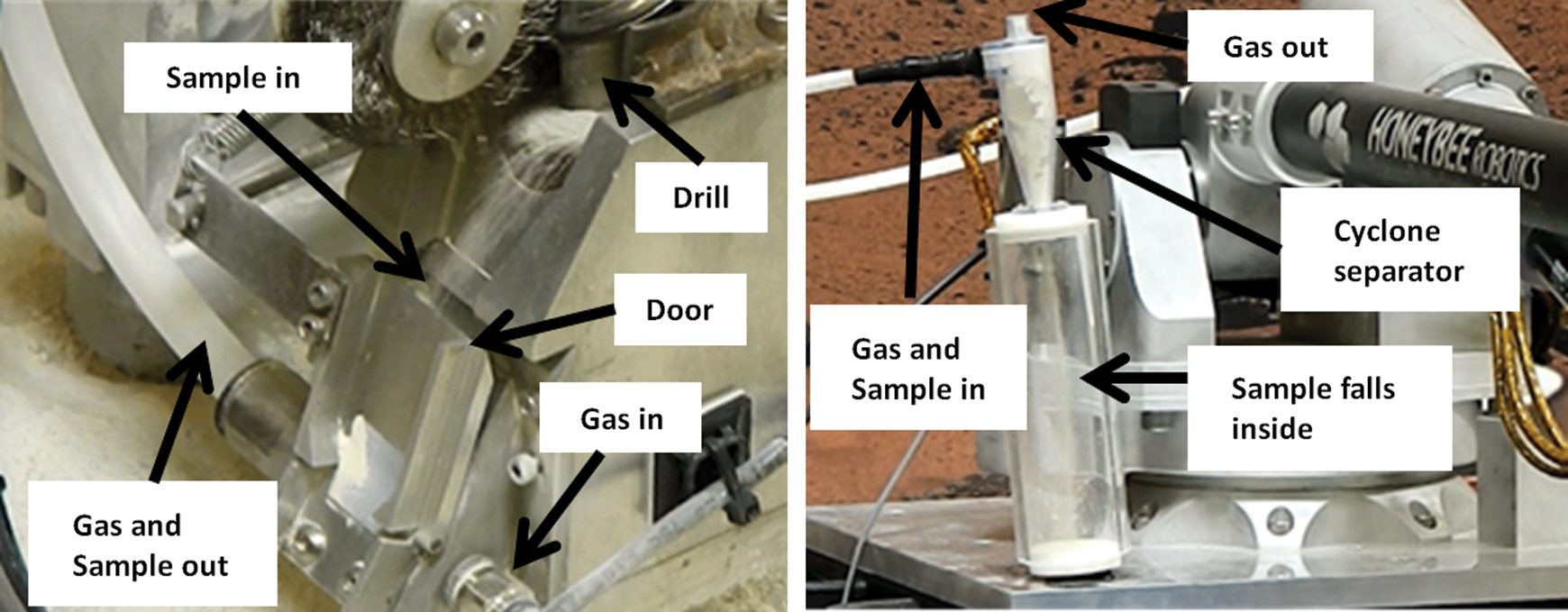
Pneumatic sample delivery system. Initially, cuttings are acquired into a chamber (left). A puff of gas transfers the content through a tube and into a cyclone separator on a lander deck (right). Color images available online at

Pneumatic sample delivery system undergoing tests in a Mars chamber. Color images available online at
The major benefit of this sample delivery approach is that a sample can be moved directly from the drill to the instrument, and this could be accomplished without the need to pull the drill out of the hole or even the need to stop the drilling operation. In fact, the sample could be transferred every few minutes while the drill penetrates into the subsurface. To recover the sample from the bottom of the hole, the drill, however, would need to be pulled all the way out of the hole and the sample from the sampling auger section scraped into the sample chamber.
The pneumatic system of course requires gas supply. Gas could be supplied from a dedicated gas cylinder, or it could come from the pressurant tank. A lander's propulsion system contains either a helium or nitrogen-filled high-pressure tank for pressurizing propellant. Upon touch down, this gas is no longer required and hence could be used for the pneumatic sample delivery system. It should be noted that MSL SAM uses helium gas as the carrier gas in the gas chromatograph instrument. Helium is used because it is inert; hence, it will not react with the sample. Compressed helium was also used in the Viking biology experiments. It is also suitable for a life search mission as it cannot give a false positive for organics content.
6.3. Three-DOF-DOF arm and drill
The third approach to sample transfer uses the drill itself and its 3-DOF deployment arm. As mentioned earlier, the drill stores sample within the deep flutes just above the bit. Once the drill is retracted from the hole, the sampling portion of the auger is protected inside the auger tube (Fig. 25). The arm then lifts the entire drill off the surface and positions the tip of the bit above the instrument inlet port (Fig. 26). Positioning the drill above the cup ensures there is an air gap, which satisfies NASA Planetary Protection requirements in the case of an unsterilized lander (Davé et al., 2013). Once the sample drop-off position has been verified, the drill can advance forward while slowly rotating. The sample then gravity falls directly into a cup. For more cohesive or sticky samples, the drill can engage percussion, which would also help to dislodge small rocks.

Sample delivery using the drill and 3-DOF arm. Color images available online at
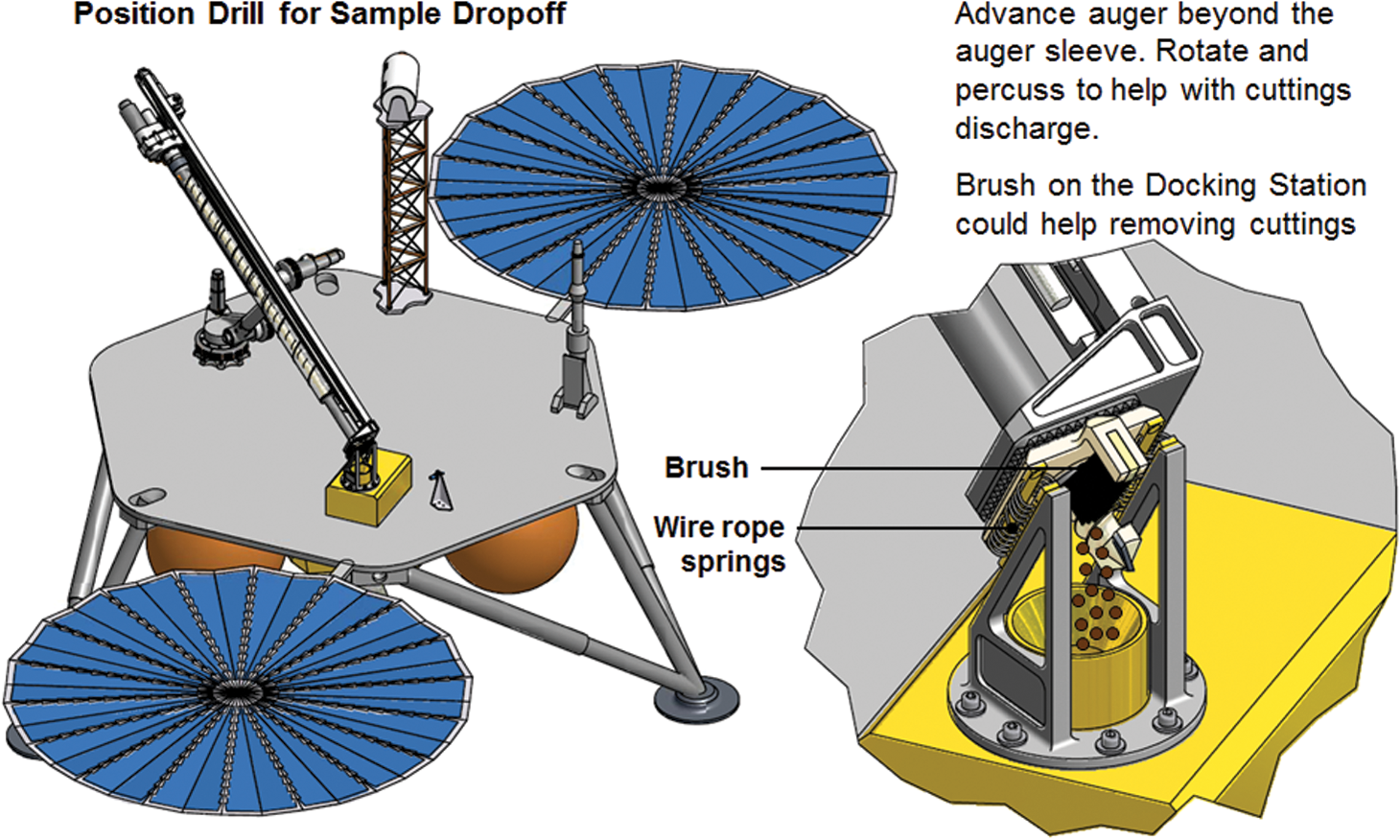
A brush on a docking station above the instrument inlet port could assist in cuttings discharge. Color images available online at
An alternative approach would be to mount a brush within the drill docking station above the instrument inlet cup as shown in Fig. 26. Hence, the brush could help with sample discharge from the deep flute auger while the auger is being rotated. An instrument could have individual inlet ports with individual docking stations and brushes. This will minimize cross contamination between samples since the brush will most likely be full of cuttings after the discharge operation. It would also require DHMR of the individual docking station because the drill would make direct contact with it.
7. Icebreaker Drill Tests
Drill testing is one of the critical aspects of drill development. It is the results of drill tests that drive any future changes to the drill design, the drilling protocols (the drilling steps or approach), and the drilling software. Normally, the technology development progresses via a continuous loop of breadboarding, testing, modification to the breadboard or manufacturing of a new breadboard, and further testing, until the final prototype is ready to be manufactured for a flight mission.
One important factor that needs to be emphasized is that in order to determine the drill nominal operation, the initial test formation needs to be very homogeneous. As such, rocks whose properties have been evaluated should be used. Examples of such rocks include Indiana limestone and Berea sandstone, offering a range of strength and abrasiveness. The drill should also be tested at relevant vacuum conditions and temperatures, since these would affect the way mechanical subsystem and actuators work. For example, drilling in hard vacuum may reveal abnormally high rotary torque due to wearing off of dry lubricant on gears. If the rock is not homogeneous, such a torque increase would be incorrectly attributed to changes in rock properties. Only once the drill system has been evaluated under relevant conditions is the drill ready for tests in a range of analog environments.
Because of limitations imposed on drilling by the environment, as well as by the mission itself, the drilling process needs to be efficient and effective. For this reason, Icebreaker was designed to drill fast with lower power and low WOB. Icebreaker has been targeting a penetration rate of 1 m/hr at an average power level of 100 W and with WOB less than 100 N. Hence, a term 1-1-100-100 was coined, which refers to drilling at 1 m in 1 hour with 100 W and 100 N WOB. These four are also primary drilling parameters from which other metrics such as drilling energy or penetration rate can be calculated. Meeting the 1-1-100-100 level would mean that the Icebreaker drilling mission to Mars fits within any expected mission limitations or requirements.
7.1. Test environment
Tests in relevant environments advance the technology to a higher TRL. For the drill to achieve the highest possible TRL on Earth, that is, TRL 6, the drill has to be tested in similar conditions as it will experience en route to a target planetary body and while performing tasks on that body. TRL 6 is defined as a system/subsystem model or prototype demonstration in a relevant environment (ground or space) (Mankins, 1995).
Testing of drills or any other hardware is an essential but very expensive element of the technology development process. For that reason, testing is a fine balance between deciding what needs to be tested, how it should be tested (under what conditions), and what budget is needed. In practice, the project budget drives the first two. In addition, testing itself is not the only major task. Building of experimental setup (chambers, ground support equipment, test beds), as well as analyzing the data, could take as much time (or more) as performing the actual tests.
For the Icebreaker drill targeting Mars, the relevant environment includes ambient temperature, pressure, atmospheric gas, humidity, formation type and temperature, gravity, and vibration and thermal environment during launch from Earth and during EDL at Mars.
Gravity, though an important aspect to drilling, is impossible to simulate on Earth. Hence, the gravity was dealt with by scaling down the maximum drilling forces by a ratio of martian to terrestrial gravities. In some cases, certain aspects of drilling such as pneumatic cuttings transfer could be tested during reduced-gravity flights. These flights allow for a target gravity level (e.g., Moon, Mars, and microgravity) to be maintained for approximately 20 s. If vacuum is a critical aspect, a vacuum chamber could be placed inside a reduced-gravity plane. Hence the effect of vacuum and the effect of gravity could be tested at the same time (Zacny et al., 2011). If a longer-duration test is required, a possible option could be offered by commercial suborbital flights. Private companies such as Virgin Galactic, XCOR, Armadillo Aerospace, Blue Origin, and Masten Space Systems are all developing suborbital spacecrafts, and these will be available for testing science payloads. If a few minutes of reduced gravity is not sufficient, the last resort, albeit an extremely expensive one, is to test the system within a centrifuge on board the International Space Station.
To meet the vibration requirements, the drill would need to be tested across frequencies it will experience during the launch and EDL. To meet the thermal requirements, the drill would need to be tested in a thermal vacuum chamber across a range of temperatures it will experience en route to Mars and while on Mars' surface. Designing a drill to such requirements and performing actual tests is very costly; hence, it was decided that the Icebreaker drill would not undergo vibration and thermal tests, but instead all tests will be focused on drilling performance.
For the Icebreaker drill development with application to martian ice-cemented ground, a testing sequence was divided into two complementary efforts. One part involved testing in a vacuum chamber, while the other part involved testing in an analog environment on Earth. The reason for such a split was to take advantage of the major learning and improvement opportunities each environment had to offer.
7.2. Testing in a Mars environmental chamber
The Icebreaker drill was thoroughly tested in a Mars chamber for two reasons: to determine whether its critical percussive mechanism would perform efficiently in a low-pressure Mars atmosphere and to acquire drilling telemetry and identify drilling faults in various Mars analog formations.
A box-shaped Mars chamber, shown in Fig. 27, was especially designed and built for testing drill systems to at least 1 m depth. The chamber itself is 3.5 m high to maximize head room for integrating a long drill string and a test sample underneath it. The height of 3.5 m could also be extended in both directions (up and down) by adding 50 cm diameter cylindrical extensions to the existing 50 cm flanges at the top and the bottom of the chamber. The chamber has a footprint 1 m×1 m to enable integration of large samples with cooling coils and still have plenty of room for instrumentation. A set of 12 acrylic windows integrated into the two chamber doors allows viewing of the drill and drill operation. A set of cameras is also placed at various strategic locations within the chamber, and movies are taken of the entire drilling process.

The Icebreaker drill integrated into a Mars environmental chamber. Material for drilling is placed inside a cylinder and actively cooled with cooling coils. Color images available online at
The chamber does not have an in-wall cooling system. Instead, only the sample and potentially the drill could be cooled (although this was not performed during the tests). Cooling of the sample was achieved via cooling coils connected to either a closed-loop refrigeration system or liquid nitrogen. The closed-loop refrigeration has a cooling capacity of 150 W at its lowest temperature of −25°C and allows close control of the temperature. The liquid nitrogen cooling system allows reaching much lower temperatures, in the range of −200°C. The sample temperature could be controlled by increasing or decreasing the flow of liquid nitrogen coolant through the coils, but the temperature is not as easy to control as in a closed-loop cooling system.
The Icebreaker drilling parameters that can be controlled include WOB, rotational speed of the auger (rpm) and percussive frequency. Drilling telemetry includes drilling time and depth (which are converted to ROP), auger power and percussive power (which are converted to total power), drilling energy (product of ROP and total power), and bit temperature.
Drilling power is a sum of auger power (rotary torque * rpm) and percussive power (impact energy * impact frequency). Since auger rpm is the same at 100, the auger power is therefore a direct function of auger torque. While testing, the percussive system was activated only if the WOB required to maintain a set penetration rate exceeded 40 N. Percussive power was constant at 35 W since neither impact energy (2.6 J) nor frequency (810 BPM) was changed. Percussive frequency can be changed by changing rpm of the actuator, but during our tests, this parameter was kept constant. Percussion was either turned on or off; hence for the purpose of energy calculation, the average percussive power was calculated as a fraction of time the percussive mechanism was turned on. For example, if the percussion system was on for only 25% of the time, the average percussive power was 0.25 * 35 W=8.8 W.
The Mars analog formations used for the Icebreaker drill testing included
(1) Mars Mojave Simulant regolith with a large fraction of small pebble-sized rocks, which was saturated with water containing 1–2% perchlorate salt and frozen to −200°C;
(2) Mars Mojave Simulant regolith saturated with water and frozen to −20°C;
(3) Ice at −20°C;
(4) Ice with 1–2% perchlorate at −20°C.
Mars Mojave Simulant is a basaltic Mars simulant made from crushing of saddleback basalt collected in the Mojave Desert (Peters et al., 2008). Perchlorate salt was added because the Phoenix and recently the MSL missions indicated the presence of perchlorate salts on Mars (Hecht et al., 2009).
The first drilling tests were conducted on Indiana limestone. Although that rock is not the best Mars analog, it is an ideal rock for verifying nominal drill operation and establishing a benchmark. Indiana limestone is (1) a uniform rock (2) of medium strength (45 MPa UCS) and is (3) non-abrasive.
The first attribute—uniform rock—means that any changes in drilling telemetry can be identified as off-nominal drill operations or possibly inefficient cuttings removal. This could be dealt with by frequently tripping the drill out of the hole to clean the auger of cuttings. If the rock had layering, fractures, and so on, these would make the interpretation of drilling telemetry more difficult. Rock uniformity essentially reduces the number of test variables.
Medium rock strength allows sufficient testing of drill motors, mechanisms, and drill bits without unduly wearing these components out. Since strength is medium and not low, the percussive mechanism would be engaged. Softer rocks would not require percussion, while drilling in very hard rocks would take longer time and wear out the drill bit faster.
Since the rock is non-abrasive, the bit wear would be minimal. Drilling in abrasive rocks (rocks that contain quartz) would significantly wear out the bit, and in turn drill performance could be different at the beginning and at the end of a 1 m hole.
A reason for establishing the base mark for the Icebreaker system is that after drilling additional holes in various Mars analog formations, the drill could be tested in Indiana limestone once again to quantify deterioration of its performance (e.g., wear of cutting bit, mechanical components) over time and footage of rocks drilled.
Figure 28 shows an example of drilling telemetry acquired during a 1 m drill test in Indiana limestone. Plotted telemetry included ROP, WOB, drill bit temperature, specific energy, and total power. The auger rpm was set to 100 and percussive frequency to 810 BPM. Hence, blows per revolution were 8.1 (i.e., the drill hammered 8.1 times every revolution). The test was done at 3 torr vacuum and ambient temperature of 26°C. The drill bit diameter was 25.4 mm.

Icebreaker drilling telemetry in Indiana limestone. Color images available online at
It can be noted that ROP and power gradually increased with depth while WOB in fact dropped over the same depth range. This is counterintuitive, since lower WOB should lead to lower ROP and in turn lower drilling power. The increase in ROP with a drop in WOB can be attributed to corkscrewing effect. The rubbing of auger flutes on the borehole wall combined with cuttings drag as they are being moved up the flutes can pull the auger into the hole in a similar way a corkscrew advances into a cork just by rotating it. This phenomenon was observed by Apollo astronauts drilling into lunar regolith on the Moon. They observed that it was unnecessary to push on the drill to maintain penetration rate. The drill auger would pull itself deeper into the hole. On Apollo 15, the penetration rate was too high, and cuttings were not cleared out of the hole sufficiently fast. This led to auger choking and precious time lost while the astronauts struggled to free up the auger. In 2010, we performed drilling tests on the slopes of the Mauna Kea volcano in Hawaii in tephra (lunar analog soil). We used a 700 W handheld rotary-percussive drill and a set of 25.4 mm diameter augers that could be screwed together to reach a 5 m depth. During the drilling tests we observed the same corkscrewing tendency of the auger as the Apollo astronauts did. In fact, initially the drill did choke, and it took a lot of effort to pull it out of the hole. Subsequently, the drill had to be lifted up to reduce penetration rate and in turn avoid future auger choking.
Figure 28 also shows that values for the drilling power, WOB, and energy are in the range of what a spacecraft could provide on the surface of Mars (or the Moon). The power was less than 70 W, WOB was less than 90 N, and energy to drill to 1 m depth was less than 100 Whr. The average ROP was 1 m/hr. Hence, the Icebreaker drill maintained the 1-1-100-100 level in these conditions and formation type.
It should also be noted that the drill bit temperature never exceeded 50°C or approximately 25°C above the formation temperature. The bit temperature initially increased at a depth of 114 mm due to higher specific energy and then dropped as soon as the specific energy also dropped. The specific energy (as opposed to drilling power) gives much closer correlation to drill bit temperature (Zacny et al., 2008).
Figures 29, 30, and 31 show ROP, power, and drilling energy obtained from drilling into various formations at 760 torr (Earth atmospheric pressure) and 6.4 torr (average Mars pressure at the Mars Phoenix landing site). The x axis shows formation types, with increasing formation strength. Data in Fig. 31 are combined from data in Figs. 29 and 30. It should be noted that Phoenix pressure of 6.4 torr is above the triple point of water pressure of 4.5 torr, and in turn, it is feasible for liquid water to form.
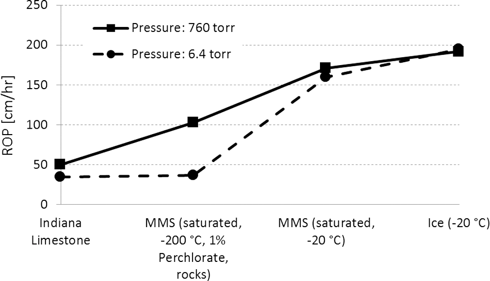
Icebreaker ROP as a function of formation type and atmospheric pressure.

Icebreaker power as a function of formation type and atmospheric pressure.

Icebreaker drilling energy as a function of formation type and atmospheric pressure.
Drilling energy, calculated as power/ROP, gives an approximate value of energy required to drill to 1 m depth. In all tests, remaining drilling parameters were kept the same. These include rotational speed of 100 rpm, percussive energy of 2.6 J/blow, and percussive frequency of 810 BPM. It should be noted that only formation temperature was changed, while the ambient temperature remained at approximately 25°C. The drill bit diameter was 28.6 mm.
Results indicate that there is a noticeable difference in ROP, power, and energy between the two pressure regimes. In particular, the power is higher and ROP lower (leading to higher energy) at a pressure of 6.4 torr. It is believed that this difference is due to the cuttings removal rather than drilling. That is, we did not observe that the strength of rocks, ice, or icy regolith increased with a drop in pressure. However, in our previous studies we observed that the cuttings flow is less effective at 6.4 torr and even less effective when the atmosphere of 6.4 torr has been purged with dry nitrogen to decrease the humidity level.
In general, the drilling power never exceeded 100 W, while ROP ranged from 40 cm/hr for Indiana limestone to ∼200 cm/hr for ice at −20°C. The energy ranged from 20 Whr/m to 200 Whr/m. The WOB was software-limited to below 100 N. Hence, this set of tests demonstrated drilling at close to 1-1-100-100 level.
7.3. Testing in Mars analog sites of Antarctica
The high-elevation areas of the Dry Valleys of Antarctica are an ideal Mars analog site for many reasons. The temperatures are always below freezing; hence, ice-cemented ground is formed through vapor diffusion from the air to the ground, as is the case at the Mars northern polar regions (Lacelle et al., 2013). The top layer, often 20 cm or more deep, is desiccated sand and silt; the ice-cemented ground or sometimes relatively pure ice lies below this dry frozen regolith layer (Fig. 32). This layering is similar to what was found at the Mars Phoenix landing site and is expected elsewhere on Mars (Smith et al., 2009).
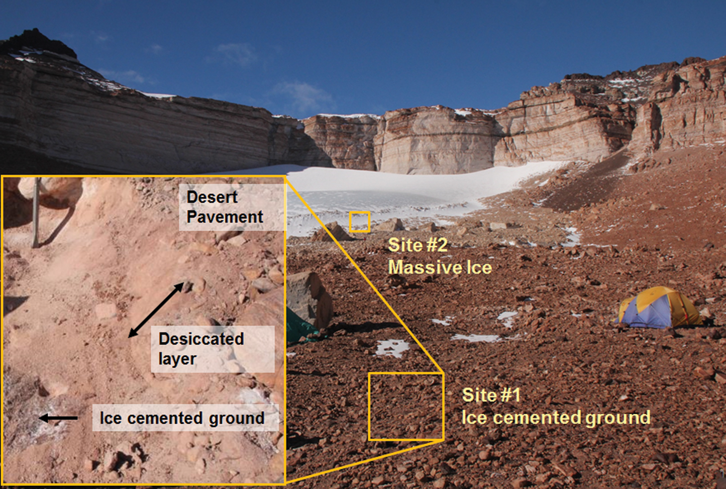
Drill sites at the Antarctic Dry Valleys (University Valley): Site #1 was ice-cemented ground, while Site #2 was massive ice. Color images available online at
The Icebreaker drill was deployed at two sites in University Valley (77°51.891′S, 160°48.029′E, elevation 1700 m), as shown in Fig. 32. The first site included ice-cemented ground, while the second site included massive ice. The drill was tested three times to a depth of 1 m in ice-cemented ground and once to a depth of 2.5 m in massive ice. The ice-cemented ground temperature at the depth of 1 m was −19°C, while the temperature of massive ice at the depth of 2.5 m was −25°C; the mean annual temperature at the site is −25°C (Marinova et al., 2012). In each case, the drill was placed on a ∼10° slope to demonstrate off-vertical operation. The drill followed the bite sampling routine.
Figure 33 shows drilling telemetry in ice-cemented ground when the bite approach was implemented; that is, the drill was pulled out of the hole every 10 cm to deposit the sample and clean the auger flutes. The depth of 1 m in ice-cemented ground was reached in 50 min, and the average penetration rate was 1.2 m/hr. The penetration rate is relatively constant with depth. The occasional dips are due to the drill being pulled out and lowered back into the hole, and the remnants of data processing. The maximum power was in the range of 100 W, of which 60 W was attributed to the percussive system, while 40 W to the auger (i.e., drilling and cuttings removal). The WOB was software-limited to less than 100 N. The percussive system was triggered once WOB would exceed 40 N. The total drill energy to reach 1 m and sample nine, ∼100 mm bites (the first bite was never sampled because it was dry regolith) was approximately 100 Whr. Hence, Icebreaker demonstrated drilling at the 1-1-100-100 level. Note that the percussive power and the total power increased at ∼100 mm depth. This was the depth to ice-cemented ground. Between the surface and 100 mm depth, the regolith was dry and easy to penetrate. Below the 10 cm depth, the drill encountered icy regolith, which was as hard as ∼40 MPa rock (Li et al., 2001; Ma and Chang, 2002). Hence, from 100 mm depth onward the percussor was automatically turned on to maintain steady penetration rate at low WOB. It should be noted that this telemetry could therefore be used to determine depth to ice-cemented ground or help with selective sampling (e.g., sampling only dry or ice-cemented ground).
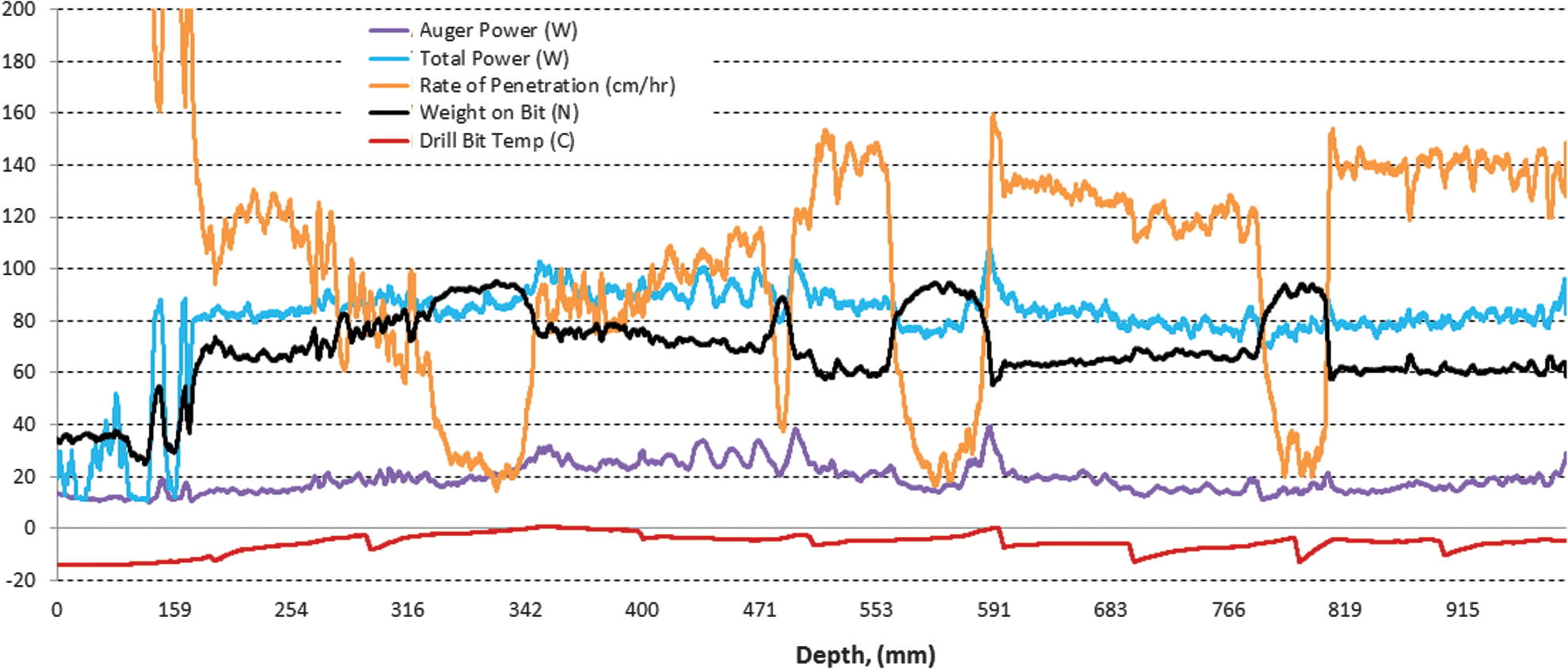
Icebreaker drill telemetry during tests in the ice-cemented ground in the Antarctic Dry Valleys—a Mars analog site. The drill used the bite drilling approach. The test data shows auger power and total power (percussive power=total power − auger power), ROP, WOB, and temperature of the drill bit. Color images available online at
The bit temperature graph shows troughs every 100 mm or so. These indicate the depths where the auger was pulled out of the hole to deposit a sample. It can be seen that there are only nine such events, which is because the first 100 mm sample was not retrieved—it was dry regolith. In all cases, the bit temperature was initially low, and with depth it kept increasing. However, the bit never reached temperatures above freezing, indicating that the temperature control routine worked satisfactorily (the routine changes drilling parameters to maintain drill bit temperature at or below 0°C). The frequent sample and auger retrieval out of the ground allowed both the auger and the formation to cool down.
Figure 34 shows the Icebreaker drill telemetry from drilling a hole approximately 50 cm from the hole reported in Fig. 33. The main difference is that, in the current test, the drill continuously drilled to 800 mm depth, while previously it followed the bite sampling routine. As before, it can be seen that the depth to ground ice is approximately 223 mm; up to this depth, the power was very low, of the order of 20 W, while penetration rate was in excess of 200 cm/hr. At the depth of approximately 223 mm, the drill encountered ice-cemented ground, and in turn the penetration rate dropped. As a result of drop in ROP, the WOB increased to try to maintain penetration rate. Once it crossed the 40 N threshold, the percussive system was engaged to further increase ROP. Engaging the percussive system increased total power by 70 W. Additional power increase was attributed to higher auger torque. From the moment the drill encountered ice-cemented ground, there was a steady decrease in penetration rate from 100 cm/hr at 223 mm to 10 cm/hr at the 800 mm depth. This was mirrored by the increase in auger power from 100 to 180 W. The drop in ROP and increase in auger power is attributed to poor cuttings removal out of the hole. Since the hole was being drilled continuously, cuttings occupied the entire length of the auger within the hole. As the hole got deeper, the distance cuttings needed to travel to the surface got progressively longer, and in turn the auger frictional drag increased. It is worth pointing out that during the duration of the test, the temperature subroutine was successful in keeping the bit temperature at or below freezing. The two drill tests, as shown in Figs. 33 and 4, demonstrated that when using a bite routine, drilling power is lower, penetration rate is faster, and bit temperature is lower than when drilling a continuous hole.
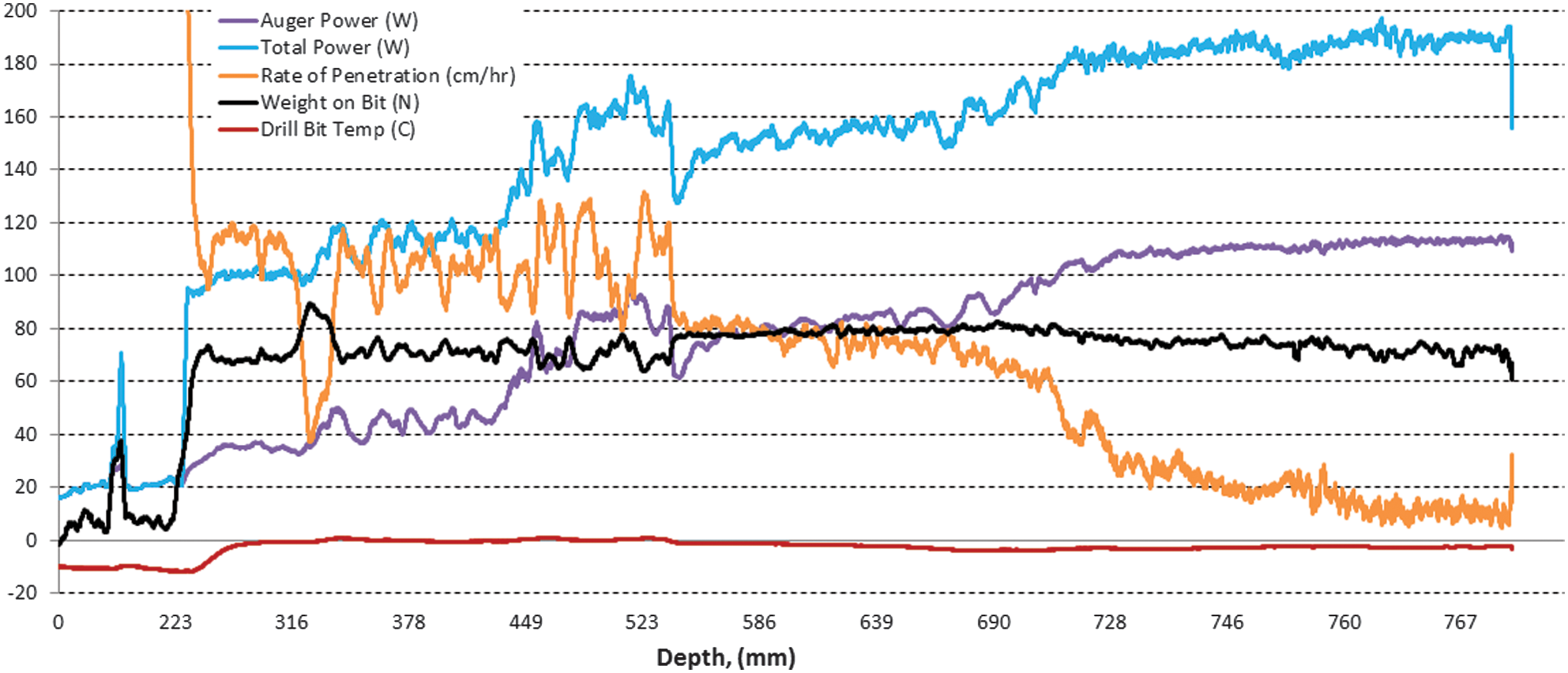
Icebreaker drill telemetry during tests in the ice-cemented ground in the Antarctic Dry Valleys—a Mars analog site. The drill continuously drilled to 800 mm depth. The test data shows auger power and total power (percussive power=total power − auger power), ROP, WOB, and temperature of the drill bit. Color images available online at
Figure 35 shows the drilling telemetry in massive ice to a depth of 2.5 m. During this test, initially a bite routine was implemented to a depth of 1 m followed by continuous drilling. Every zigzag on the temperature curve corresponds to the drill pull-out event to empty the cuttings. Drilling telemetry to 1 m depth with the bite routine was quite uniform. However, past 1 m depth, the telemetry mirrors that in Fig. 34; that is, the power would increase while penetration rate decreased.
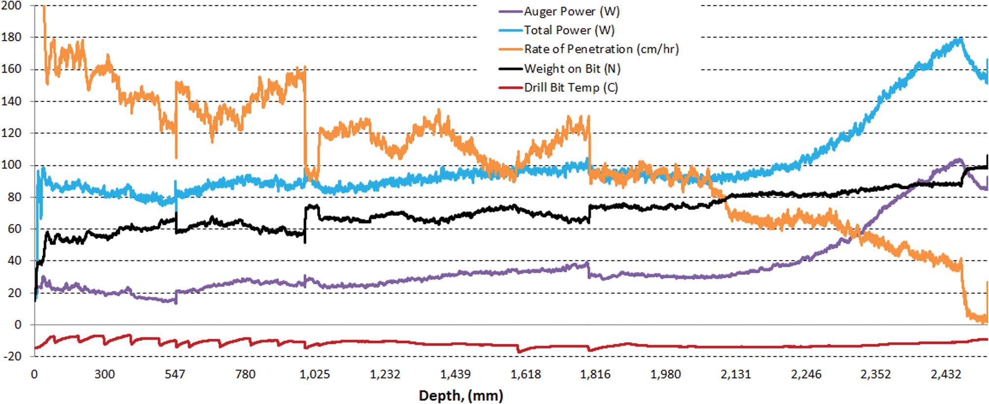
Icebreaker tests in massive ice in the Antarctic Dry Valleys—a Mars analog site. The test data shows auger power and total power (percussive power=total power − auger power), ROP, WOB, and temperature of the drill bit. Color images available online at
In this test, the auger was quite effective to 2 m depth in clearing the cuttings, but just below 2 m the auger power started to increase almost exponentially. Note that the increase in power was not due to drilling into a harder substrate, since the bit temperature remained low at −20°C during the entire drilling process. If the formation became harder, this would be reflected in higher drilling power and in turn bit temperature, since drilling power is associated with formation destruction and in turn heat.
During the course of the test, the WOB was <90 N, the average ROP was 1 m/hr (it took ∼2.5 hours to reach the 2.5 m depth), and the average power was 100 W. Hence, the total energy was ∼250 Whr or 100 Whr/m. This test demonstrated that it is feasible to drill to 2.5 m in massive ice with relatively low power, but it also illustrated the importance of frequently cleaning up cuttings to keep the power low.
In all three tests, the bit temperature was always at or below freezing, and this helped keep cuttings cold. In addition, the air temperature in the Antarctic Dry Valleys was always below freezing; hence the entire drill system, including the auger, was cold. The drill string therefore acted as a heat pipe and helped to dissipate heat formed during the drilling operation. The cold Antarctic air was also very dry. The low temperature and low humidity helped keep drill cuttings frozen. Cuttings were also shielded by a drill platform from direct solar radiation. Figure 36 (left) shows cuttings acquired by drilling into the ice-cemented ground. It can be seen that these cuttings do not stick but rather fall as if they were dry granular media (particles). The same was observed with ice cuttings, which did not stick and also preserved large ice chunks as shown in Fig. 36 (right). This observation is of paramount importance to the Icebreaker mission, as it shows that it is possible for icy cuttings not to stick. The major factor is keeping the cuttings temperature low during the drilling operation by implementing suitable drilling protocols and by shielding them from direct sunlight once on the surface. From an operational standpoint, it might be prudent to land with a drill facing away from the morning Sun, thermally isolate the sample collection mechanisms from the instrument deck, and perform drilling and sample transfer operations early in the morning (or at night, if energy budget allows).
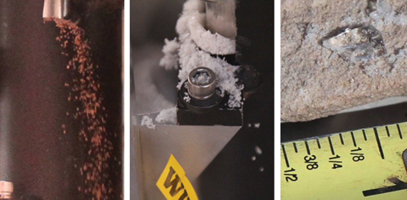
Left: ice-cemented ground and ice cuttings acquired by the Icebreaker drill in the Antarctic did not stick. Right: cuttings from drilling in ice-cemented ground. Center: ice cuttings. Right: Ice cuttings contained single ice crystals 5 mm large. Color images available online at
8. Next-Generation Icebreaker: The Icebreaker2 Drill
The Icebreaker2 drill represents the third generation of Honeybee Robotics rotary-percussive 1 m class drills (see Table 3). The first generation, the CRUX drill, was a 2 kW system that was incapable of operation in a vacuum (Zacny et al., 2010e). However, it confirmed the benefit of percussive systems for planetary applications and in particular low WOB requirement to achieve nominal penetration in a range of soils, icy soils, and rocks (Paulsen et al., 2010). The second generation, the Icebreaker drill, has been thoroughly tested in vacuum chambers and in the Arctic and Antarctica, and demonstrated drilling at 1-1-100-100 level; that is, 1 m in 1 hour with 100 W and 100 N WOB (Paulsen et al., 2011). To reduce the development cost, the drill was not mass-optimized and weighed over 40 kg. The Icebreaker2 drill shown in Fig. 37, which is almost as powerful as Icebreaker (∼400 W vs. 300 W), has a slightly lower percussive energy (2 J/blow vs. 2.5 J/blow) but weighs only 10 kg (Zacny et al., 2013c). The drill has been mass-optimized to reflect a “flightlike” design. The drill has already been deployed in Greenland and Devon Island (Canadian High Arctic) in the summer of 2013. The drill will also be extensively tested in the Mars environmental chamber. Figure 37 also shows the mock-up lander, which is slightly larger than the size of the 2007 Mars Phoenix and 2016 Mars InSight mission landers.
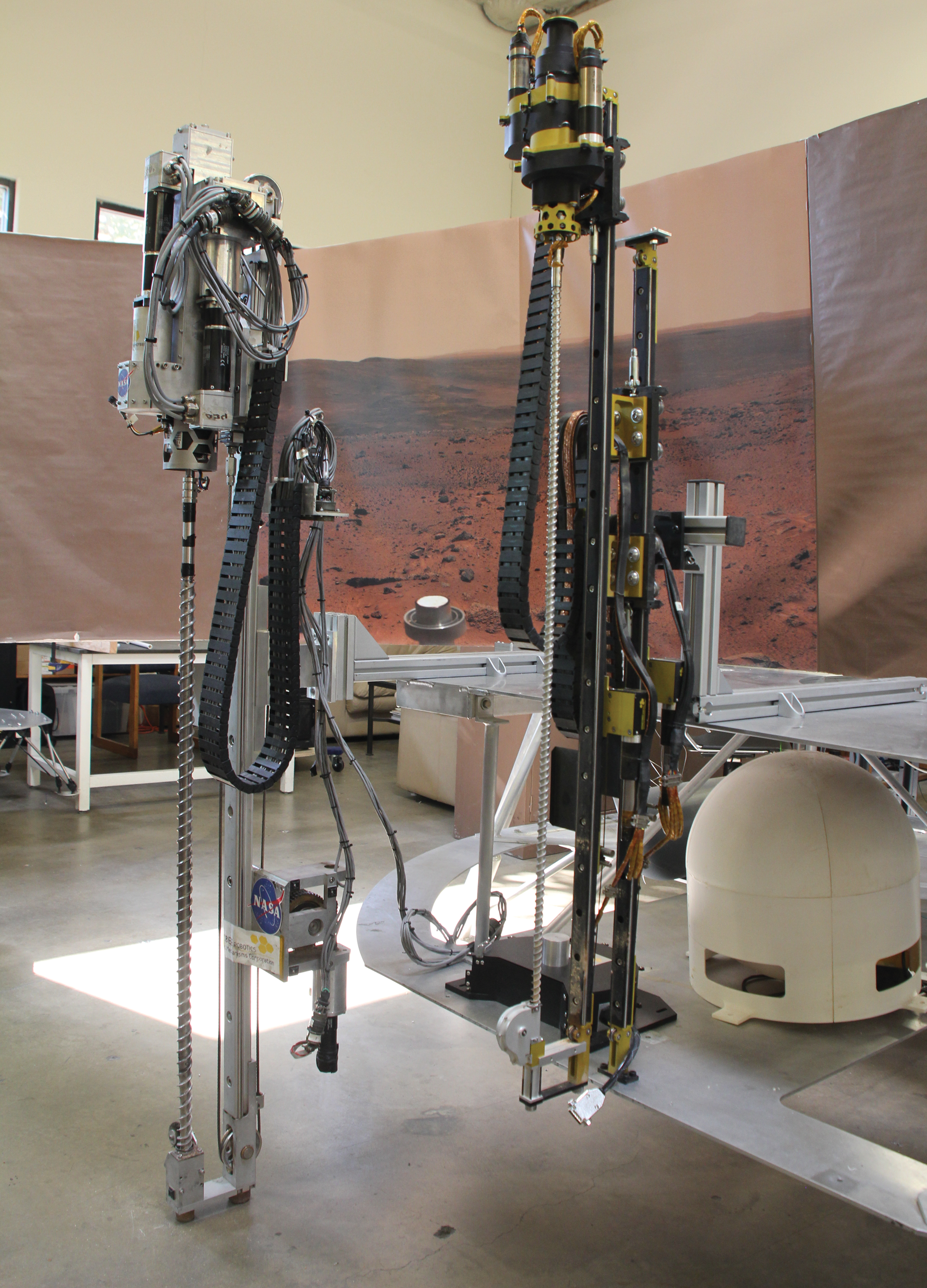
The second- and third-generation rotary-percussive drills: Icebreaker (left) and Icebreaker2 (right). Icebreaker2 has similar capabilities as Icebreaker but weighs only 10 kg. Color images available online at
It should be noted that Icebreaker2 has a twin: the LITA drill. The LITA drill has been integrated with the Carnegie Mellon University Zoe rover and was deployed in Atacama, Chile, in the summer of 2013 as part of the NASA Astrobiology Science and Technology for Exploring Planets–funded project LITA: Life in the Atacama (Cabrol et al., 2013). The drill autonomously drilled to a predefined depth and delivered sample to a sample manipulation system (a carousel with 20 cups) for analysis by the Mars Microbeam Raman Spectrometer (MMRS) and a UV-stimulated fluorescence imager called BUF (Wang et al., 2013).
Neither Icebreaker nor Icebreaker2 were subjected to vibration tests associated with the launch or EDL at Mars. Hence, they are not at TRL 6. However, both drills have endured vibrations associated with various modes of transportation: airplanes, trucks, ground vehicles on rough terrains (in the Arctic), ATV, hand carried, and dropped from a height. Both drills were shipped across the continents: Icebreaker went to Antarctica and the Arctic; Icebreaker2 and its sister drill, the LITA drill, went to the Atacama, the Arctic, and Greenland.
9. Conclusions
This paper presents the development and testing of the Icebreaker drill, a critical element of the Mars Icebreaker mission (McKay et al., 2013). Its goal is to acquire aseptic samples and deliver them to life-detection instruments on the deck of the lander. The Icebreaker drill is a 1 m class, arm-deployable drill system. The drill has been under development since 2005 and currently is at TRL 5/6.
The drill employs a rotary-percussive approach to drilling, which reduces WOB and energy requirements. The drill rated power is 400 W; however, the average drilling power is in the range of 100 W. The drill initially weighed 40 kg; however, the mass has been reduced to 10 kg through use of lighter materials and several design modifications.
The Icebreaker drill has been tested in the Mars analog sites of the High Arctic and Antarctic Dry Valleys, as well as in a vacuum chamber. In all tests, the drill penetrated into a variety of formations with limited power and WOB. As a useful mnemonic, the drill has been designed to maintain 1-1-100-100 performance level—that is, 1 m in 1 hour with 100 W and 100 N WOB. Thus far, all drilling tests maintain this or lower level, with a few exceptions where power reached 180 W.
An integral part of the Icebreaker drill is its drilling software. The software has been developed via two parallel efforts. NASA Ames has been focusing on implementing a high-level control and diagnostics, while Honeybee Robotics has been focusing on rule-based algorithms.
The drill uses a bite sampling approach whereby the drill is retracted every 10 cm or so to deliver the sample to a sample transfer system. Frequently retracting the drill out of the hole has many advantages. It allows the subsurface to cool down, it reduces the volume of cuttings that need to be augered out of the hole, and stratigraphy could be maintained to within 10 cm. In addition, since analysis of each sample will no doubt take several sols, it is prudent to keep the drill above the hole during this time rather than risk freezing it in the hole.
The drill includes three independent sample delivery systems. The pneumatic sample delivery is a point-to-point system. As soon as the sample is augered out of the hole, it is captured inside a small chamber. A puff of gas clears the sampling chamber and delivers the precious cargo directly into a target instrument. The 3-DOF arm that deploys the drill can also be used in conjunction with a drill as a sample delivery tool. In particular, once the drill is above the surface and sample captured around the bit, the arm can position the tip of the bit above the instrument inlet port. The drill can percuss and move the auger with the cuttings forward to dispense the sample directly into a cup. The third approach uses an independent 5-DOF arm with a scoop at the end. The scoop is positioned close to the sample drop-off point and, upon capturing the sample, delivers it to a target instrument in the same way the Mars Phoenix arm delivered a sample inside a scoop.
Since the Icebreaker mission is a life-detection mission targeting Mars Special Regions, the drill has been designed in such a way as not to preclude sterilization by DHMR.
The Icebreaker drill could also be used as a science instrument. Its bit-embedded thermocouple could provide thermal gradient data, which combined with estimated thermal conductivity could be used to estimate martian heat flow. The drilling telemetry could be used to estimate formation UCS, and UCS combined with subsurface temperature could be used estimate the fraction of ice present in the subsurface.
Footnotes
Acknowledgments
The research reported in this manuscript was funded by the National Aeronautics and Space Administration (NASA) Astrobiology Science and Technology for Exploring Planets (ASTEP) and Astrobiology Science and Technology Instrument Development (ASTID) programs: NASA Contracts NNA09DA97C “Mars Umbrella Drilling Scout (MUDS)”, and NNX11AJ87G “Robotic Investigation of Subsurface Life in the Atacama”. Testing in Antarctica was supported by the US Antarctic Program as part of the National Science Foundation Office of Polar Programs.
Abbreviations
ALSD: Apollo Lunar Surface Drill.
BPM: blows per minute.
CheMin: Chemistry and Mineralogy.
CHIMRA: Collection and Handling for In situ Martian Rock Analysis.
DHMR: dry heat microbial reduction.
DOF: degree of freedom.
EDL: entry, descent, and landing.
GCMS: gas chromatograph–mass spectrometer.
ISAD: Icy Soil Acquisition Device.
MER: Mars Exploration Rovers.
MSL: Mars Science Laboratory.
PADS: Powder Acquisition Drill System.
RAT: Rock Abrasion Tool.
ROP: rate of penetration.
SAM: Sample Analysis at Mars.
SA/SPaH: Sample Acquisition, Sample Processing and Handling.
SSA: Surface Sampler Assembly.
TRL: Technology Readiness Level.
UCS: unconfined compressive strength.
WOB: weight on bit.