
Abstract
In the Solar System, the surface of an icy moon is composed of irregular ice formations at cryogenic temperatures (<200 K), with an oxidized surface layer and a tenuous atmosphere at very low pressure (<10−6 atm). A lander mission, whose aim is to collect and analyze biological samples from the surface ice, must contain a device that collects samples without refreezing liquid and without sublimation of ice. In addition, if the samples are biological in nature, then precautions must be taken to ensure the samples do not overheat or mix with the oxidized layer. To achieve these conditions, the collector must maintain temperatures close to maintenance or growth conditions of the organism (<293 K), and it must separate or neutralize the oxidized layer and be physically gentle. Here, we describe a device that addresses these requirements and is compatible with low atmospheric pressure while using no pumps. The device contains a heated conical probe with a central orifice, which is forced into surface ice and directs the meltwater upward into a reservoir. The force on the probe is proportional to the height of meltwater (pressure) obtained in the system and allows regulation of the melt rate and temperature of the sample. The device can collect 5–50 mL of meltwater from the surface of an ice block at 233–208 K with an environmental pressure of less than 10−2 atm while maintaining a sample temperature between 273 and 293 K. These conditions maintain most biological samples in a pristine state and maintain the integrity of most organisms' structure and function. Key Words: Europa—Icy moon—Microbe—Eukaryote—Spacecraft. Astrobiology 17, 709–720.
1. Introduction
T
Radiation damage to biomolecules and organisms is an important consideration in our ability to detect them. Predicted radiation at the surface of Europa varies from 0.05 to 5 Gy/day depending on the location of measurement at leading or trailing hemispheres, respectively (Paranicas et al., 2009). Estimates of radiation depth penetration are an important consideration prior to sending a lander to investigate the presence of biological material. Paranicas et al. (2009) and Teodoro et al. (2016) estimated very little radiation penetration at multimeter depths in pure water ice over a period of 100,000 years. For example, the length of time to accumulate 100 eV per H2O molecule (standard radiolysis energy) is approximately 30,000 years for the first centimeter. In areas of increased salt concentrations, which cause higher-density solids that are dosed with heavier atomic species including MgSO4, the penetration depth is predicted to be less. It is also predicted that large differences of surface radiation intensity exist up to 100-fold (Paranicas et al., 2009); therefore, it will be important to choose a landing site that has low radiation intensity, which allows biomaterial to exist closer to the surface.
Radiation toxicity of microbes is a well-studied area, and where radiation exists microbes have adapted with some incredible resistance mechanisms including rapid double-strand DNA repair, up to 10 genome copies per cell, and high concentrations of manganese and antioxidants in the cytoplasm (Battista, 1997; Zahradka et al., 2006; Slade and Radman, 2011). In particular, Deinococcus radiodurans has a 37% survival at 15,000 Gy (J/kg) and 100% survival at 5000 Gy (J/kg), which is compared to the radiation range at the surface of Europa of approximately 0.05–5 Gy/day depending on the location (leading to trailing hemispheres, respectively). At a depth of 10 cm, the radiation is decreased a further 100-fold, giving 0.0005–0.05 Gy/day. Depending on the temperature and hence DNA repair rate, D. radiodurans could survive a minimum of (5000/0.0005) days = 1 × 10⁷ days (or 27,000 years) and much longer if repair and growth conditions existed for even a few days. Of course the process of evolution should endow europan microbes with even more advanced adaptations to their own environment; hence we expect further extensions of longevity.
Examples of microbes remaining viable in frozen glacial ice for 750,000 years on Earth have been reported (Christner et al., 2003), indicating that similar outcomes may occur in an icy moon's subsurface. In the case of Europa, the surface age is estimated at an average of 20–200 million years (Bierhaus et al., 2009) and in some locations could be much younger, which falls into the time frame of these earthly microbes' extended longevity.
In the event that microbes are not sustainable in the first 50 cm of surface ice, analytical devices may still be able to detect the signature of biomolecules. The probe described in this article could collect ice melt that is suitable for equipment that detects proteins and DNA, fluorescence, molecular mass, and shape/particle distribution, which can be used in series or parallel to the flow of liquid sample.
The two recent mission reports by teams exploring a Europa lander and sampler (Europa Study Team, 2012; Pappalardo et al., 2013) identified several criteria for the mission, and by incorporating the authors' points and extending them to account for the preservation of biological life, we came up with an enhanced set of seven requirements, as follows: (1) An aqueous sample is required for preserving life. (2) Icy moon microbes are not necessarily heat tolerant, and it is necessary to maintain the temperature below an arbitrary critical point, for example, 293 K (70°F, 20°C). (3) The low pressure on the surface of a moon (McGrath et al., 2009) requires isolating the sample water or ice from a low-pressure environment. (4) The design must also maintain itself in a nonfrozen state until all the samples have been captured and analyzed. (5) The melting mechanism must be economical in its weight and energy requirement. The energy required to heat ice from 123 to 273 K, and then supply latent heat required to melt ice at 273 K, is 500 J/mL water; plus there are conductive heat losses around the probe that add further requirements. The current requirements for a small craft are 35 kg in mass of which 10% could be battery weight, which relates to 20 kW for current rechargeable lithium batteries. The current probe fits this criteria by being highly localized with the application of heat to the sample and thus uses much less power than is available. (6) It is essential to add a biobarrier to the system in order to contain organisms of terrestrial origin within the craft. (7) An oxidized upper layer must be separated from potential organic molecules and organisms that may be present in the lower levels.
In addition, it would be advantageous to remove pumps from the system so as to reduce the risk of failure.
There have been approximately 10 collection devices sent to Solar System planets and Earth's moon. Their designs have included drills and scoops that collect the sample and send it to a heating stage for analysis. This type of processing is ideal for collecting regolith and rock samples that are physically tough and chemically resilient, although an exception could be martian regolith, which is thought to contain perchlorates that are reactive when heated and modify the sample's chemical composition (Ming et al., 2014). A biological sample is collected in a very different way; primarily, the sample is collected in the most undisturbed way, and precautions are taken to preserve the structural and functional aspects of life. In the case of ice samples collected from terrestrial sources, they are collected as frozen samples in cores or blocks and melted carefully to retain control over the temperature and pressure (e.g., Brinkmeyer et al., 2003; Christner et al., 2003). Finally, samples are analyzed by microscopy while supplemented with nutrients in order to observe growth and division. To achieve this process on the surface of an icy moon requires technological development to ensure sample preservation, while including a growth chamber with microscopic observation. The volume of meltwater to analyze can be estimated from extreme terrestrial samples, which vary from 100 to 106 microbes per milliliter (Brinkmeyer et al., 2003; Pappalardo et al., 2013); thus, by using the ubiquitous life assumption, only 50 mL of meltwater would give a greater than 99.9% chance of observing life if it existed in the sample.
In this report, we focus on sample collection via a heated probe with a conical shape, which seals the meltwater from the atmosphere and directs it up the central core of the probe to the first reservoir. Subsequent fluid movement is produced by vacuum suction from a second reservoir. The pressure differential is achieved by closing the system at one end and heating the liquid sample to expand gases in the first reservoir. Thus, we overcome three main obstacles: (i) Preservation of biological structure and function by using mild conditions, (ii) Reduction of sublimation at low atmospheric pressure, (iii) Engender fluid flow by using indigenous vacuum conditions rather than pumps.
2. Methods
2.1. Probe head design
The main criterion of the whole probe assembly was to provide 50 mL of meltwater from −80°C ice in a vacuum environment of <10−2 atm. The probe parts were designed on e-CAD software and manufactured by e-Machine Shop (Mahwah, NJ, USA) (Fig. 1). The first probe was 3 cm in diameter and contained a deep groove for the heating element and a central orifice for melted water flow (see Fig. 1A, 1B, design MH05). The edges of the probe were sharp to create a seal between the ice and head, which would force meltwater up the central orifice. There are two attachment threaded holes that allow the probe to be firmly attached to the column. Stainless steel and aluminum were tested; stainless steel is tougher than aluminum, but the latter has a higher heat capacity and heat transfer rate. Aluminum was used in all designs after MH05 to utilize its greater heat transfer rate. The 12-degree angled conical melting surface was chosen based on the design of liquid chromatography column head pieces, which are designed to collect fluid evenly from the bottom of an aqueous chromatography column (e.g., GE Healthcare liquid chromatography columns). In addition, the central orifice was tested at 1 and 3 mm diameters (compare Fig. 1A and 1D, designs MH05 and MH93a, respectively), and circumference sealing points were tested versus flat edges (compare Fig. 1D and 1G, designs MH93a and MH93m, respectively). Also, the depth of the collection tube insert was lowered when moving from MH05 to MH93a (compare Fig. 1A and 1D), and the spacing between the heating element and the central orifice was increased when moving from MH93a to MH93m (compare Fig. 1D and 1G).
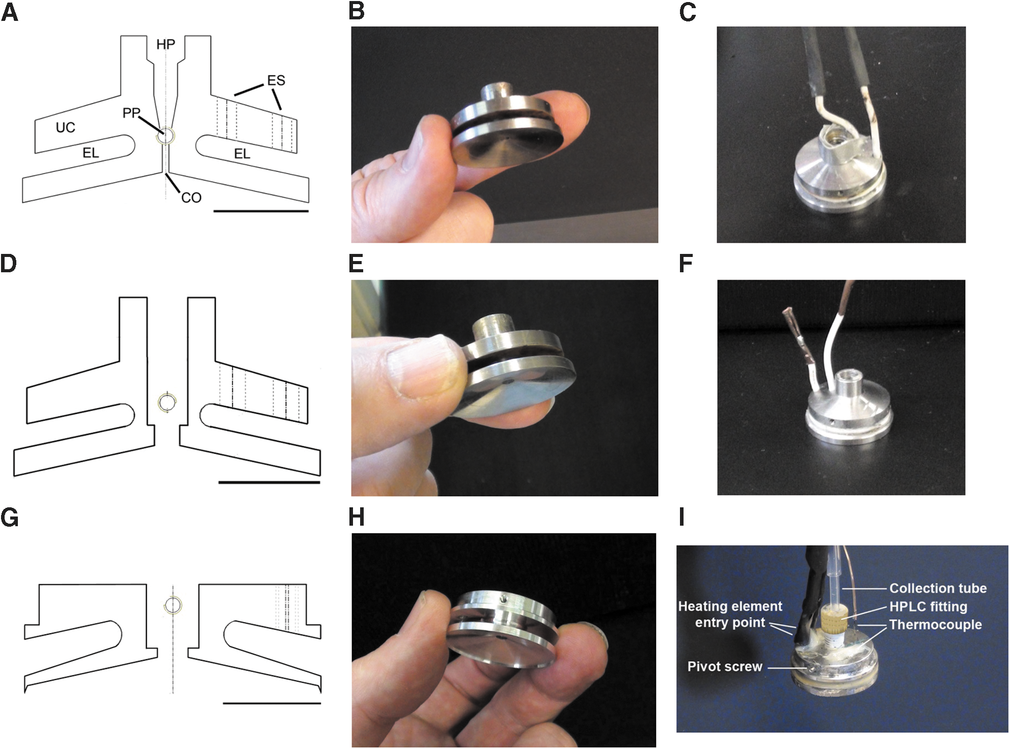
Schematic and actual probe heads. (
When latent and specific heating components are combined, the energy required to melt 50 mL of −150°C ice to 283 K is approximately 25 kJ. A 1 h limit was placed on the collection process because the longer the process the less efficient it will be due to heat losses. Thus, the probe was designed to utilize 30 W (30 J/s) of heating energy, which should take approximately 45 min to collect 50 mL of water (80 kJ). This required 30 cm of 16 Ω/m nichrome heating cable, which was provided by Ozark Assemblies, Inc. (Part. # E192725, Bridgeton, MO, USA). The heating cable was de-threaded by removing the glass fiber outer woven layer, which exposed a layer of silicon rubber surrounding the coil of nichrome wire, which was wound around a core of fiberglass. This heating wire was sufficiently flexible to allow threading through the head piece at right angles to the threading holes, with six or seven coils filling the groove (Fig. 1C, 1F, 1I). A second heating coil was placed in the probe column (called a sheath) that provides heating to reduce the risk of freezing the column to external ice or meltwater inside the device (Fig. 2A). The same heating wire was used, except the woven fiberglass layer was left intact, and a 100 cm length gave 16 Ω resistance for an energy usage rate of 10 W or total energy requirement of 27 kJ.
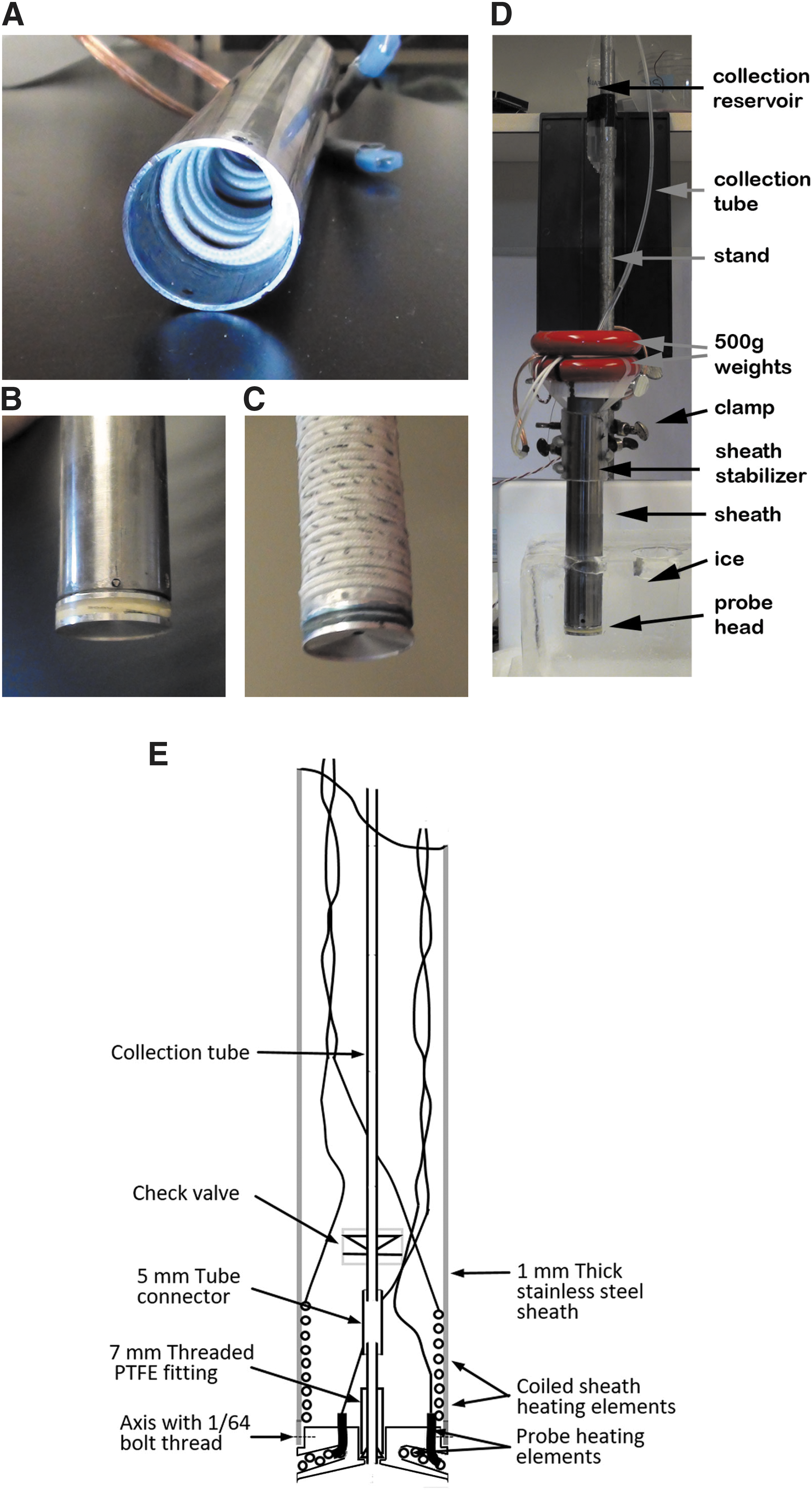
Probe and sheath assembly. (
The probe head was attached to the sheath with two opposing screws to complete the assembled probe (Fig. 2B). This was the format of the fixed and mobile head pieces. A third format was the silicone rubber mounted head piece, which created a semiflexible mounting (Fig. 2C). The probe assembly was then either mounted on a stand for room-temperature experiments (Fig. 2D) or into the vessel for environmental chamber studies (see below). Figure 2E shows a cross-sectional diagram of the assembled probe for clarity.
A 12–36 V power source that was used for power and temperature control of the probe head was achieved by using a thermocouple connected to a temperature regulator (Part # JLD612, Versatile Control & Technologies HK, CN). The thermocouple was attached to the top of the probe head metal surface with epoxy glue (Fig. 1I). A second temperature probe was inserted into the central sample collection orifice in some scenarios, which enabled measurement of the meltwater temperature that must not exceed 293 K (20°C) in order to preserve biological integrity.
The cross-sectional area combined with the cylindrical probe column was designed to provide enough volume for microbial analysis. Based on microbial counts in various terrestrial environments, there could be anywhere from 100 to 106 microbes per milliliter; thus we chose 50 mL as a suitable volume to capture this range. The cross-sectional area could also be varied based on the available force that can be applied and the force necessary to melt ice and create fluid flow.
In some scenarios, meltwater backflow was controlled with a check valve to eliminate loss of sample. The gravity-independent check valve was obtained from US Plastics (Lima, OH, USA, Cat. # 57171).
2.2. Low temperature and pressure environment chamber
The low-pressure sub-freezing-point chamber was a modified freeze-dryer model 3640 from Northstar FreezeDry Co. (Naswok, IL, USA) (Fig. 2A). The cylindrical chamber was 90 cm in diameter and 2 m long, which creates a volume large enough to contain a thick ice sample and the enclosed system vessel. The chamber could maintain a pressure of 10−4 atm and a temperature of −32°C. However, due to the time dependency of the −40°C and −80°C ice experiments, a vacuum pressure of only 10−2 atm could be obtained.
Super cooled blue-colored ice was made by freezing a solution of 0.00005% (w/v) bromophenol blue in water in a Styrofoam box placed inside a −80°C freezer for 4 days. A thermocouple set in the ice recorded the internal temperature of the ice block, which recorded a temperature of −65°C with a cryogenic T-type thermocouple. The discrepancy between −80°C and −65°C was due to the freezer cycling on and off and providing a higher average temperature than suggested from the digital display of the freezer. Other ice block temperatures, −20°C and −40°C, were obtained by placing the ice block in −20°C and −40°C freezers, respectively, for 2 days. On several occasions, ice at −100°C was produced by dipping the −65°C ice block in liquid nitrogen for 5 min.
2.3. System and vessel design
To enable operation inside a low-pressure sub-freezing-point chamber, an insulated vessel was constructed that contained all the elements of the system's design. A polystyrene foam vessel was constructed with 4 cm thick walls and a view panel for observation (Fig. 3A). Radio control was used to control valves, and the mechanism to release the probe and weights was used to create force (red objects). A high-pressure liquid chromatography (HPLC) valve was used to regulate the pressure of the second reservoir by exposure to the ambient vacuum or closed to build up pressure. The probe sheath was stabilized by two circular retainers, and the force-providing weights (500 g each) were attached to the top of the sheath (red objects in Figs. 2 and 3). A release mechanism controlled by a servo was installed to activate the probe movement when the system was ready for the procedural sequence to start.
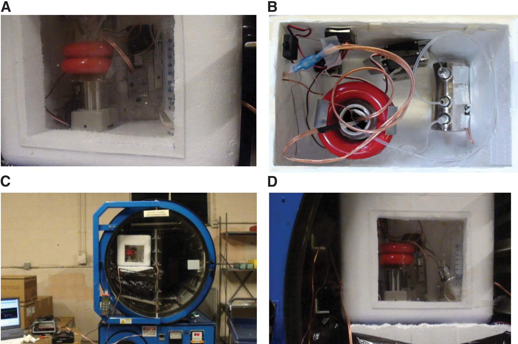
Probe assembly located in the insulated vessel. (
2.4. System operation
The melting procedure was initiated by turning on the heating element, releasing the sheath, and lowering it with force onto ice. The environmental pressure was either 1 atm or 0.01 atm. After several minutes, meltwater began to flow and was either collected in a nominal vessel or a reservoir. Meltwater was colored blue with bromophenol blue dye in order to observe its movement. Force was applied to the column in the form of two 500 g weights (1000 Nm). (Note: Due to the lack of gravitational force in the final lander scenario, this force could be applied by motors or spring-loaded pulleys.) Reservoir water was further moved through the system by closing the reservoir valve to the environment and using a heating element attached to the reservoir. This created a pressure differential that forced liquid out of the reservoir and into the next reservoir or potential analytical device.
3. Results
Initial tests indicated that the MH05 head piece melted −20°C ice with sufficient speed with 30 cm of 16 Ω/m heating element while keeping the temperature at the heating element at approximately 40°C (Fig. 3A). The temperature in the central channel varied from 10°C to 40°C due to erratic melting cycles, which is not suitable for collection of biological samples. The first aspect that was tested was the diameter of the central hole, which was found to be too narrow (1 mm) in the initial design (MH05) to allow water to flow up the tube. A 3 mm hole allowed water to flow unimpeded (design MH93a). Later observations of the ice shape left after melting indicated a central mini-cone shape about 2–3 mm wide at its base, which may have plugged the narrow-diameter hole but was small enough to allow the 3 mm diameter hole to be operational. This aspect could be modified if colder ice were to create the same problem.
In the next series of experiments, the water pressure was measured with a kilogram mass applied to the probe column (Table 1). MH05 did not produce meltwater in this scenario. MH93a created a 3 cm height of water before the flow of water stopped and went into reverse and water rapidly flowed out of the probe head. Interestingly, when the head only was pushed into the ice by hand, a much higher water height was achieved (15 cm); thus some difference between the column design and the hand pressure method was changing the efficiency. We realized that the flexibility imparted by hand pressure was sealing the edge of MH93a and allowing a greater height of water; therefore, we loosened the attachment mechanism of the head to the column by expanding the retaining holes by 0.5 mm. The head now moved around a two-point axis and moved approximately ±1 mm on its farthest edge from the axis. When the new assembly was tested, fully assembled with a 1 kg force, the water height was 45 cm. This height was equivalent to 54 g/cm2 of probe head pressure, which was equivalent to 48% of the force applied to the column. The end result of creating any water height was a catastrophic back flow of all the water, which obviously had breached the head piece/ice interface. Increased pressure allowed a higher level to be reached as shown in Table 1, but we wanted to limit the required force applied to the probe to 1 kg in view of the difficulties of applying high force at the final destination. The semiflexible silicon-gel mounted probe head (Fig. 2C) did not produce meltwater beyond a 3 cm height, that is, the same outcome as the rigid probe format.
Constant power heated-probe experiments were performed on −20°C ice blocks at 1 atm. The probe assembly was essentially the same as in Fig. 2D with the probe attached to a sheath plus a 1 kg mass for force generation. For experiments containing the check valve, this was inserted in series with the sample flow tubing above the probe head. In experiments to determine the height of water, the collection tube was extended above the sheath by 2 m, and the water height measured directly on the tube. F = fixed probe head; M = mobile probe head; nnV = voltage applied to probe head heating element, where nn is the number of volts; NTC = no temperature control of probe head.
The temperature of surface ice on Europa is obviously much cooler than −20°C, so we tested −40°C, −65°C, and −100°C ice beds in the same format. The decreasing temperature increased the time to the first meltwater and reduced the rate of production (Table 2). The temperature profiles are shown in Fig. 4B, 4C. Basically, the probe head temperature increased initially until a maximum was reached (50–70°C) when the first melting occurred; then a steady decline was noted due to meltwater surrounding the head—in deep −20°C ice the lowest temperature leveled out at 20–25°C. Meltwater production rates were 1.5–3.0 mL/min. The probe failed to function at temperatures of less than −80°C due to the probe temperature not being able to reach above 0°C.
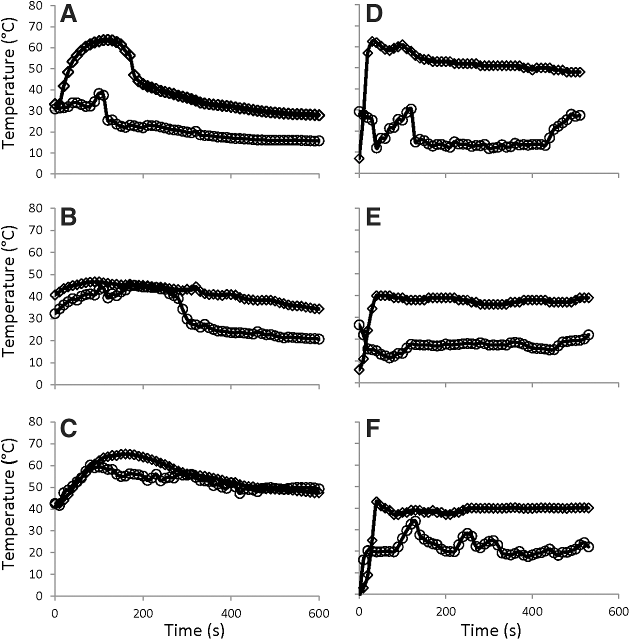
Representative temperature profiles of heating element (open diamond) and sample (open circle) thermocouples. Probe assemblies were heated above the ice for (
Ice melting experiments performed on −20°C, −40°C, and −65°C ice blocks at 1 atm. The probe assembly was essentially the same as in Fig. 2D with the probe attached to a sheath plus a 1 kg mass for force generation and a collection vessel at a height of 40–60 cm depending on how far the probe had moved into the ice block. No check valves were used in these experiments. F = fixed probe head; M = mobile probe head; nnV = voltage applied to probe head heating element, where nn is the number of volts; NTC = no temperature control of probe head; TCnn = temperature control, where nn is temperature in °C.
A check valve was employed to reduce backflow. This was successful and facilitated collection of 40 mL of fluid at an elevation of 30 cm above the probe head. The check valve needs to be gravity-independent because icy moons have low-gravity environments.
Figure 4 shows temperature profiles of the probe head and sample-collecting orifice. In the non-temperature-regulated graphs at 1 atm (Fig. 4A–4C), the profiles are erratic, and often the sample temperature was above 20°C. The sample collection rate was also intermittent and resulted in highly variable sample temperatures. In the temperature-controlled experiments at 1 atm (Fig. 4D–4F), the profiles were much less erratic (see, e.g., Fig. 4D), and due to the constant flow of meltwater through the central orifice, the sample temperature remained below 20°C for the majority of the time. In general, it was found necessary to maintain flow in order to maintain a low sample temperature.
Many experiments were performed at 10−2 atm, at subzero temperatures, and using -65°C cooled ice (see Table 3 for examples). The low pressure was created with a large modified freeze-dryer that generated an environment of <10−2 atm and −32°C. Initial tests with MH93a indicated large losses to evaporation as would be expected from liquid water in a low-pressure environment. Thus, MH99m was designed such that it included two modifications to increase the seal between head and ice. First, the heating element location was moved to be closer to the lower-circumference edge compared to the center of the head, and second a concentric pointed protrusion was added to the lower circumference to more sharply impinge on the ice. These adaptations resulted in two advantages: (i) greater pressure at the probe head (144 cm head of water, equivalent to 172 g/cm2 of probe head pressure) and (ii) reduced losses in the low-pressure environment as indicated by collection of fluid in the first reservoir. The pressure value was 20% more than theoretical, based on 1 kg mass creating 1000 Nm−1 force across a head surface area of 7.0 cm2. This discrepancy may be due to the force being applied to partial areas of the ice/probe head interface, for example, the outer edges more than the inner areas. The efficiency of water collection was approximately 80% based on the volume of probe and sheath versus the volume of meltwater collected. An example of the MH93m probe in operation is shown by the time lapse images in Fig. 5 and by a supplementary video (available online at
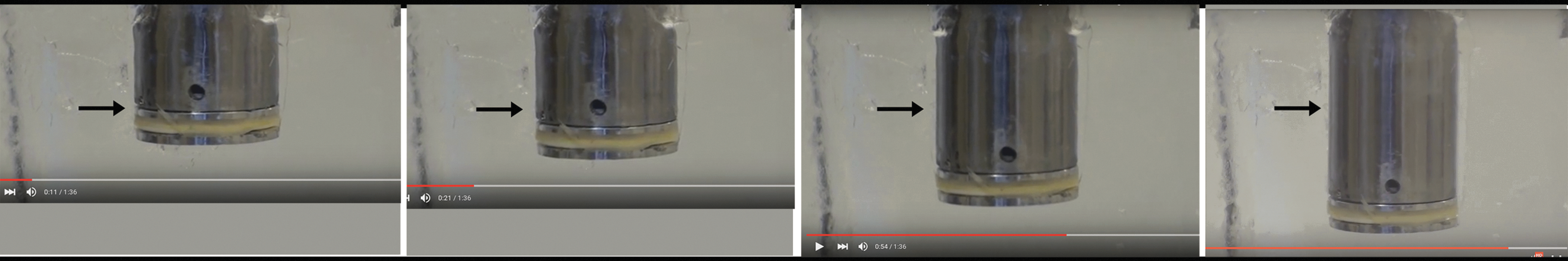
Time lapse images of the probe moving through ice. The probe assembly was placed on a −20°C block of ice, and a video recording was taken through the ice. Temperature control was used on the probe head at 40°C. The video time frames are left to right at 11, 21, 54, and 84 s, respectively. The arrow indicates a stationary point in the ice and has a length of 1 cm.
Ice melting experiments performed on −40°C and −65°C ice blocks at −32°C (−26°F on the chamber's display) and 0.01 atm in the environmental chamber. The probe assembly was essentially the same as in Fig. 3 with the probe attached to a sheath plus a 1 kg mass for force generation, which was contained in an insulated vessel and a maximum collection height of 22–40 cm depending on how far the probe had moved into the ice. The whole vessel assembly was placed in the subzero low-pressure environmental chamber. There were no check valves used in series with the collection tube, although we found it necessary to add a check valve to the collection reservoir outlet to retain enough pressure so the meltwater would not boil. F = fixed probe head; M = mobile probe head; nnV = voltage applied to probe head heating element, where nn is the number of volts; NTC = no temperature control of probe head; TCnn = temperature control, where nn is temperature in °C.
The MH05 design caused the sample to be heated constantly beyond 20°C as shown by the values recorded from a thermocouple located in the central orifice (Fig. 4A); thus the depth of the collection tube insert (HPLC fitting) was lowered for design MH93a and MH93m (compare Fig. 1A, 1D, and 1G), which insulated the sample from the metal probe heat. Also, when moving from design MH93a to MH93m, the spacing between the heating element and the central orifice was increased (compare Fig. 1D and 1G). In addition, the application of a probe head temperature regulator controlled the erratic behavior of the melting process (e.g., compare Fig. 4A–4C with 4D–4F). These changes reduced sample temperature at the probe head to the permissible range and reduced the erratic temperature profile. It was noted that the melting mechanism failed to function at temperatures of less than −80°C due to the probe temperature not being able to reach above 0°C.
3.1. Energy utilization
The energy requirement was calculated from the Wh (VAh) when the MH093m probe head was operating with temperature regulation at 40°C and with −65°C ice; the values of 36 V and 5 A for 20 min gave an overall energy utilization of 60 Wh or 216 kJ. This value is compared to a theoretical 20 kJ for melting 50 mL of −65°C ice.
3.2. Melting heterogeneous ice samples
In some cases, the ice was irregular, and much of it contained a 1 cm thick layer of frost. Heterogeneous ice structure such as this is expected to be present on the surface of icy moons (also called firn ice). The head piece was proficient at melting this ice and creating a seal with the probe when the meltwater froze at lower depths. Thus, even if pockets of gas or vacuum exist in the ice, they are filled with meltwater and refrozen, which enables the head piece to make a seal once again.
4. Discussion
In the current design, a heated element provides energy to a metal probe head that is forced into ice to create meltwater flow. The probe head has a sharp edge that impinges on the ice, creating a seal around its periphery, which reduces losses by low pressure causing meltwater leakage. By applying enough force, the probe head seals the periphery and imparts pressure to the water, which travels upward through the central orifice into the first reservoir. The design fulfills three basic requirements as outlined in the introduction: (i) Preservation of biological structure and function by using mild conditions, (ii) Reduction of sublimation at low atmospheric pressure, (iii) Maintenance of the sample in the liquid state for analysis.
There were several optimizations to the initial design that helped improve the probe over 100-fold in water pressure and collection efficiency that enabled it to reach the required 50 mL collection volume. These included providing a wide central orifice that does not impede meltwater flow from an ice cone that forms in the center of the melted cylinder, a sharp circumference that impinges on the ice and creates a seal from the low-pressure environment, and a temperature-regulated probe that is optimized for different ice temperatures and environmental pressure. In addition, optimized design elements were added such as lower collection tube height and wider separation of heating elements from the central core, which maintained the sample meltwater temperature below 293 K, which is compatible with preserving biological samples.
Although the energy requirement is large to raise the temperature of ice and then overcome the latent heat energy for melting, the probe can achieve this with modest amounts of electrical power because it applies heat in a localized way and does not overheat the sample. Indeed, the power utilized in the present design, operating at 40°C probe temperature and melting −65°C ice, was 180 W for 20 min, and the total electrical energy requirement is approximately 60 Wh or 216 kJ. Although this is over 10 times the calculated energy for melting 50 mL of ice from a −65°C starting point, and approximately twice the heating element design energy, it is well below the 1 kWh requirement stated in the introduction. In the current work, the volume of the sample was determined solely on the concentration of possible microbes as estimated from diverse terrestrial environments as described in the introduction. In a final design, there may be a need for a greater volume if the current amount is not enough to use in all analytical systems.
The probe was able to cope with some level of heterogeneous ice (firn-type ice) that was present on top of some ice blocks stored at low temperatures for more than a few weeks. The probe was able to do this by melting the top layer, which refroze further down and created a solid ice bed on which to place the probe. Subsequently, the water ice melted again and moved through the central orifice.
Ice temperatures below −80°C were not compatible with the probe in the sense that meltwater was not obtained. Thus, future designs may need to incorporate modifications to enable operation at lower temperatures. There are several options that, among others, could include the following: (a) a more powerful heating element, (b) infrared ambient heating with LEDs, and (c) a larger concentric sheath. The larger concentric sheath would corral an area around the intended probe site. The sheath could be used to heat the ambient −160°C ice and create a warmer environment for the present probe to operate. The sheath may benefit other aspects such as (a) a barrier to contain sublimated exhausts that could be analyzed, (b) increasing the pressure of the intra-sheath environment, which would enable the present probe to operate more efficiently, (c) acting as an anchor that would be useful for an opposing force for the probe, and (d) a biobarrier for achieving compliance with planetary protection guidelines (Esposito et al., 2000). The anchor would operate by a process of melting ice and allowing refreezing, which would stabilize the probe assembly prior to lowering the probe down the middle and collecting samples.
The gravity of Europa is 13% that at Earth's surface; hence it is important to understand the limits of the probe's ability with respect to creating a force by using endogenous gravity. Currently there are two ideas on this, (a) using the endogenous gravity, which for a small lander might be 13% × 35 kg = 4.55 kg, and (b) stabilizing by melting ice anchors that would refreeze for permanent anchoring. The former option is similar to the current design, that is, using 1 kg mass as a force. The latter is preferred for the current probe design due to the requirement for a stable assembly, which would be necessary to ensure that the melting mechanism would retain the seal around its periphery.
In the introduction, we identified seven criteria that should be met for a probe to collect biological samples from cryogenic ice with structural and functional integrity. The current design approaches the criteria in the following way: (1) Samples are collected in liquid aqueous medium. (2) Due to the moderate melting temperature, a sample's temperature will not exceed 20°C for the majority of the time, which reduces the risk of sample destruction. (3) The force on the probe head allows a seal to be made with the environment, enabling separation from low environmental pressure. (4) A minimal temperature can be maintained in the vessel to keep the probe or sample from freezing. (5) The energy is supplied in a localized way, which creates very efficient energy transfer. In this report, the practical energy utilization is 10 times higher than the theoretical value for melting 50 mL of ice. If the practical value described here (60 Wh) is adjusted for melting ice at 110 K, then the energy requirement is 120 Wh. A 1 kg Li-SO2 battery will provide this energy, and with a 40% extra margin it is still below the 3.5 kg estimate (10% of 35 kg lander mass) described in the introduction. (6) Implementation of a biobarrier will be studied in the next stage of development. (7) Enabling an oxidized layer separation will also be studied in the next stage of development.
In addition to the above, the fluidic control of moving meltwater from probe to reservoir to analytical device has been achieved with the use of ambient vacuum, valves, and heating elements, all of which contribute to the reduction of the overall energy requirements and risk of mechanical breakdown.
The present study is part of a larger project to develop a low weight (10–20 kg), multipod, lander-based mission to Europa. In this regard, future developments will be centered on incorporating analytical devices that not only measure the presence of organic molecules but also assess growth and division of microbes within the vessel (Fig. 6). One major advantage with the current design is that peroxide neutralizers can be added to the fluid as soon as it is released from the ice, or the first few centimeters of ice meltwater can be diverted to another reservoir. Another key design element is to allow the lander to collect samples regardless of landing orientation, as long as the lander can anchor to the ice by way of melted and refrozen points of contact and use those “anchors” to create an opposing force for the probe head/sheath assembly. Finally, the multipod approach creates redundancy in the mission and reduces the risk of failure at heterogeneous landing sites.
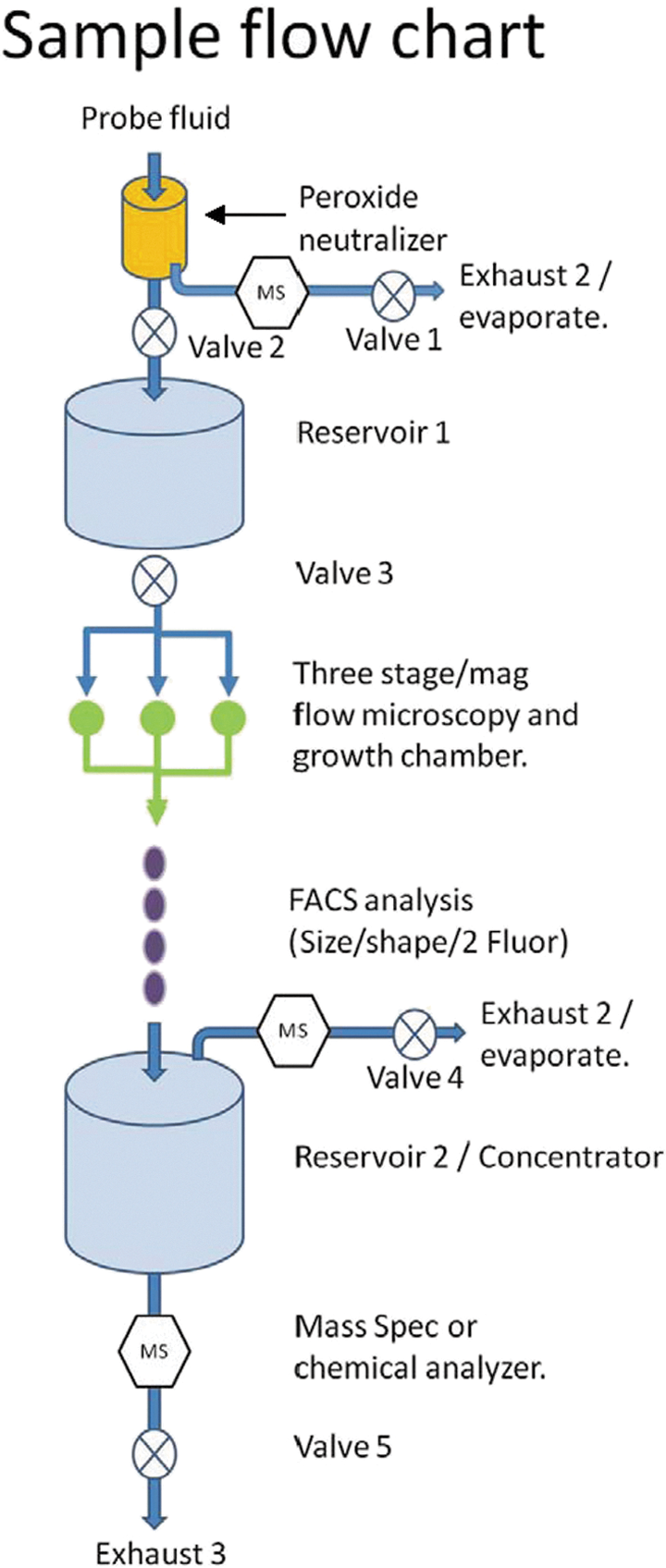
Schematic diagram of a sample flow mechanism through an analytical system contained in a putative Europa lander vessel. A system of valves and differential pressure reservoirs are used to regulate flow through the system. For example, during descent to the moon's surface, valves (V) 1, 2, and 4 are opened and closed to create vacuum in the reservoirs. This will later be used to pull the liquid through the system. Sample meltwater enters the system via the probe head; during this process, V1 is open and V2 is closed. During meltwater loading into the probe, a volume of gas could be generated due to the peroxide neutralizer reacting with peroxide in the meltwater. This gas can be analyzed by several simple metabolite detectors, which are chip-sized devices available in the molecular biology field. Once meltwater is loaded in the first reservoir, it can be propelled by residual gas production or a heater element that could boil a small amount of meltwater. In addition, vacuum that was loaded during the pod descent can be utilized if necessary. Likewise, pressure differential between the probe (or R1) and R2 (a) transports liquid through the flow microscope/growth chamber, which adheres microbes based on ionic charge, and (b) the flow continues through the particle counter/size detector. Finally, R2 acts as a concentrator for chemical analysis; opening V4 and applying heat will concentrate the liquid. The concentrate is then fed into the MS or other analytical device by opening V5. Conceivably, these components could be miniaturized to fit a 3 × 1 cubestat format.
The basic principal behind the fluidics system is to create a robust one-direction simple flow structure. In the current design, there are no pumps, which improves robustness because the liquid/mechanical interface is prone to stalling with particulates, and pumps are prone to failure after 4–5 years of non-operation. By using the low pressure of the local environment and gas production in meltwater, positive flow can be achieved with a series of valves, reservoirs, and heating elements to produce differential pressures and, hence, flow at specific points in the system. In addition, the process can be automated and follow a simple logic program for control. Figure 6 describes the schematic fluidics system in more detail. Methods of detecting microbes are varied, and the best approach will no doubt be determined by other groups in the future; possibilities include fluorescence, enzyme analysis, particle counts, and protein/DNA detection. In the immediate future, efforts will focus on maintaining microbial viability in samples that contain peroxides and improving the sample collecting potential at <173 K ice temperatures with 10−4 atm pressure.
4.1. Conclusions
We have developed a practical solution to sampling meltwater from the surface of icy moons. The design is biocompatible, energy efficient, small in size, and highly robust to low pressures and heterogeneous ice structures. It also allows separation of a highly oxidized layer that could destroy organic molecules. The next phase of this project is to improve the function of the probe assembly at lower temperatures and pressures that are in line with similar conditions on the surface of Europa. This is a key requirement that cannot be overlooked. We will be developing the mechanism that works to lower the probe with force for collection of meltwater, separation of an oxidized upper layer, and transit of the lower-layer meltwater to a growth chamber compatible with microscopic observation.
Footnotes
Acknowledgments
We thank the teams and funding partners of past and present Mars, Jupiter, and Saturn missions who inspired this research by supplying the images, chemistry, and physics that are necessary to create a vision for biological exploration. This research was supported entirely by Cytoskeleton, Inc. (Denver, CO), which provided the equipment and funds over the past several years. We also thank Dr. Kim Middleton and Dr. Royston Carter for their in-depth discussions during the probe's development and review of this manuscript.
Author Disclosure Statement
The author works for Cytoskeleton, Inc., which manufactures proteins and diagnostic kits. The designs described in this article are not the subjects of patents, and thus the author declares no competing financial interests exist.
Abbreviation Used
References
Supplementary Material
Please find the following supplemental material available below.
For Open Access articles published under a Creative Commons License, all supplemental material carries the same license as the article it is associated with.
For non-Open Access articles published, all supplemental material carries a non-exclusive license, and permission requests for re-use of supplemental material or any part of supplemental material shall be sent directly to the copyright owner as specified in the copyright notice associated with the article.