
Abstract
Antarctic subglacial lakes are often considered suitable analogues to extraterrestrial subglacial aqueous environments. Recently, an environmentally friendly RECoverable Autonomous Sonde (RECAS) was designed at the Polar Research Center of Jilin University (JLU) to sample the water of subglacial lakes without contamination. In this regard, the development of a fast-penetration thermal head is the key issue for RECAS. Two different prototypes were designed and tested at the JLU ice-well to determine the optimal design and operation parameters of the thermal heads. Practical top and bottom thermal heads were then designed based on one of the prototypes, which can penetrate ice at an average rate of 1.88 m/h. The test results for the RECAS thermal heads show that the rate of penetration (ROP) can be 1.80–1.95 m/h in −10°C ice, and the axial load on the thermal head only affects the ROP when it is lower than a specified threshold. The decrease of the ice temperature from −10°C to −30°C leads to a decrease of 17% in the ROP. The bottom thermal head can drill into dirty ice, and a simple collector positioned above the head can collect solid particles suspended in the melted ice. The top thermal head exhibited a long lifetime and stable heating performance after being powered in water for 2 weeks. In addition, the ice temperature near the borehole was monitored to evaluate the range of heat disturbance caused by the thermal head.
1. Introduction
The subsurface layers of Mars and icy satellites (such as Titan, Enceladus, and Europa) are of interest, because they host subglacial aqueous environments that are, in principle, “habitable.” This makes them of substantial astrobiological interest, and it has prompted the consideration of methods for accessing their interiors via drilling.
The idea of using hot points to access the subsurface layers of planetary ice sheets arose in connection with a proposal for a Mars mission suggested by Paige et al. (1993), which was, however, not selected by National Aeronautics and Space Administration at that time. Since then, at least seven different hot points have been developed for extraterrestrial investigations: Cryobot (Zimmerman et al., 2001), SIPR (Bentley et al., 2009), IceMole (Dachwald et al., 2014), VALKYRIE (Stone et al., 2014), SPINDLE (Stone et al., 2018), Ice Diver (Winebrenner et al., 2014), and IceShuttle Teredo (Wirtz and Hildebrandt, 2016). The use of thermal probes has also been suggested for the collection of biological samples from cryogenic ice at the surface of icy moons in the Solar System (Davis, 2017).
Some theoretical and experimental studies have been undertaken in an attempt to understand the behavior of such probes under extraterrestrial conditions—very low temperatures, vacuum, and low gravity (DiPippo et al., 1999; Biele et al., 2002; Kömle et al., 2002; Lorenz, 2012; Davis, 2017; Horne, 2018; Schüller and Kowalski, 2019). It is clear that each environment requires different technical solutions for melting probes. Dust content, salinity, temperature, and radiation vary considerably between Earth and extraterrestrial bodies. Although a heated probe deployed into an ice sheet on Earth always causes melting with subsequent refreezing, the behavior of such a probe in a low-pressure environment is quite different (Kaufmann et al., 2009; Kömle et al., 2018a). Nevertheless, it is useful to perform preliminary tests of the main components of thermal probes developed for extraterrestrial investigations in Earth's glaciers and ice sheets; for example, to study subglacial lakes in Antarctica.
The subglacial lakes of Antarctica were first discovered in the 1970s (Oswald and Robin, 1973; Robin et al., 1977). During the past 40 years, a tremendous aquatic system containing saturated sediments, rivers, streams, and lakes has been gradually unveiled by ice-penetrating radar and other geophysical measurements such as seismic sounding, satellite observation, and gravitational field mapping (Priscu et al., 2008; Wright and Siegert, 2012; Kyrke-Smith and Flowler, 2014). To date, >400 subglacial lakes have been identified, which account for ∼0.6% ± 0.2% of the Antarctic ice/bed interface (Goeller et al., 2016; Siegert et al., 2016). Subglacial lakes are considered the most promising places to find extreme life and paleoclimate information, because of their unique environment. Moreover, they are considered analogous to extraterrestrial subglacial aqueous environments.
I.A. Zotikov and A.P. Kapitsa first proposed the use of a subglacial autonomous thermal probe with a small nuclear power plant onboard in 1963, to study the Antarctic subglacial environment (Zotikov, 2006). The nuclear power plant was in a hermetically sealed container with a diameter of 0.9 m, which also included a variety of instruments and equipment. This project was never realized due to issues related to the classified status of the reactor.
We assume that only “freezing-in” thermal probes have the potential to access deep-buried subglacial lakes. The outstanding characteristic of these hot-point drills is that the wires used for the transmission of electrical power and the generated signals pay out of the advancing probe and become fixed in the refreezing meltwater above. All of the “freezing-in” thermal probes designed for in situ ice sheet detection can only drill down and never return to the surface (Aamot, 1968, 1970; Philberth, 1976; Kelty, 1995).
We proposed a more intelligent and recoverable thermal probe RECoverable Autonomous Sonde (RECAS) for subglacial lake exploration (Talalay et al., 2014). The RECAS has two thermal heads located in the top and bottom tips. The bottom thermal head can melt a hole such that melted ice refreezes behind the probe to isolate the subglacial lake from Earth's atmosphere. It is proposed that after sampling, measuring, and video recording in the subglacial reservoir, the top thermal head starts to melt the refrozen ice as it returns to the surface via the spooling of a cable in an internally stored winch.
The movement of the thermal probe is controlled by a thermal head. A fast-penetrating thermal head can deliver instruments quickly and avoid freezing in place by continuously moving. Most thermal heads can melt ice at a rate of <13 m/h, and the highest rate of penetration (ROP) up to 22 m/h was achieved by using an extremely high-power density input of ∼400 W/cm2 (Nizery, 1951). The lifetime of a thermal melting probe is highly reliant on the thermal head. For example, the deepest hole drilled by a thermal probe was stopped at 1005 m because of the failure of its thermal head in Greenland in 1968 (Philberth, 1976). Tephra layers embedded in ice sheets caused by volcanic eruption are widely distributed in Antarctica and Greenland (Mortensen et al., 2005; The IceCube Collaboration, 2013; Bourne et al., 2015; Narcisi et al., 2017). The thickest tephra layer (24 mm), which is composed of mineral particles, was found in the ice core at Dome Fuji (Kohno et al., 2004). Commonly, the mineral particles are a few tens of μm in size, and they can stop (or slow down) thermal head drilling. For a well-designed thermal head that can drill to the depth of subglacial lakes, a high ROP is required with low heat loss, a long lifetime, and the ability to drill in dirty ice.
Over the past 60 years, various thermal heads have been designed with different power, shapes, diameters, and types of heater. These factors result in substantially different drilling performance. In general, the power density of a glacial-permeating thermal head is in the range of 40–160 W/cm2. Mellor (1986) noted that according to practical experience, the maximum specific power for a long-life thermal head is <300 W/cm2. The diameter of thermal heads ranges from 18 to 250 mm (Gillet, 1975; Stone et al., 2014). Usually, the shape of the thermal head can be conical, cylindrical, spherical, or paraboloid. EnEx-IceMole utilized a complanate thermal head shape (Kowalski et al., 2016).
Previously published works contain numerous discussions on the influence of power, shape, and diameter on drilling performance. The theoretical relationship between ROP, cross-sectional area of the thermal head, ice temperature, and power was first expressed by the energy-balance equation, which was subsequently simplified by neglecting heat loss (Aamot, 1967; Ulamec et al., 2007). Many publications have discussed the appropriate choice of thermal head shape, but conflicting conclusions have been reported (Ward, 1961; Shreve, 1962; Pudovcin et al., 1988; Konstantinidis et al., 2017). Currently, there is no standard guidance for thermal head design, and many researchers rely on experimental methods to identify optimal thermal head designs or to observe drilling performance under different conditions (Treffer et al., 2006; Weiss et al., 2008). An important aspect that should be mentioned here is the strong (exponential) dependence on the environmental gas pressure. This was investigated by Kömle et al. (2018a).
In our study, two different thermal head prototypes were designed and tested in a laboratory environment to evaluate their drilling performance. Optimal and practical RECAS thermal heads were then identified, and preliminary drilling tests were performed under different conditions.
2. Materials and Methods
2.1. Power consumption of the RECAS thermal head
Talalay et al. (2014) established an estimation method for the calculation of thermal head power consumption. The specific energy consumption Q (kJ/m) is expressed as follows:
where k 1 is the coefficient that accounts for the borehole enlargement during thermal drilling; R is the diameter of the thermal probe; ρ is the density of ice; Lm is the latent heat of fusion of ice; CP is the specific heat of ice; Tm is the melting point of ice; T0 is the ice temperature; Cw is the specific heat of water; and Tf is the final temperature of the melted ice.
The total power required to thermally melt a hole is
where v (m/h) is the expected ROP; k
2 is the coefficient of thermal efficiency. For an effective design, k
1 ranges from 1.03 to 1.05 whereas k
2 is from 0.7 to 0.8. The real drilling efficiency of a thermal head is defined as
in which vr is the real measured ROP; vt is the theoretical ROP that can be derived from Eqs. 1 and 2 assuming k 1 = k 2 = 1.
The diameter of the RECAS was preliminarily determined to be 160 mm, because of constraints due to the installed inner winch and the measurement/sampling instruments. The calculated power consumption of the RECAS thermal head, based on the previously mentioned estimation method, is shown in Fig. 1. In our calculations, Tf was assumed to be 15°C, whereas T0 ranged from −60°C to −10°C. The other parameters used in the calculations were ρ = 917 kg/m3, Lm = 334 kJ/kg, Cw = 4.218 kJ/(kg·K), CP = 2.05 kJ/(kg·K), and Tm = 0°C (Cuffey and Paterson, 2010).

The relationship between power and ROP of RECAS thermal head. The dashed line indicating the expected ROP of RECAS is 1.5–2 m/h. RECAS, RECoverable Autonomous Sonde; ROP, rate of penetration. Color images are available online.
If the temperature of the ice changes from −60°C to −10°C with an expected ROP of 1.5–2 m/h, the total required power of the RECAS thermal head is 3.6–6.5 kW, and at least 4–6 months are needed to sample the water in subglacial lakes buried >2500 m beneath ice sheets. After considering different possibilities for a power supply system, the power for the RECAS thermal head was evaluated as 5 kW. Based on our estimations, it was determined that 5%–24% of the input power is used to increase the ice temperature from the initial temperature to the melting point. Further, 63%–80% is used for the phase change from ice to water, whereas 12%–15% is wasted in increasing the water temperature and, subsequently, being lost to the surrounding ice.
2.2. Design of the RECAS thermal heads
To find the optimal design of RECAS thermal heads, two different thermal head prototypes were designed with different shapes and materials, in addition to the type and distribution of the heaters. The thermal head prototypes were then tested in a Jilin University (JLU) ice-well, in which the ice temperature was adjustable from −5°C to −30°C (Wang et al., 2017). The test stand of RECAS thermal head prototypes was a simple mast with a computer-monitored instrumentation system that measured the ROP, axial load, and temperature (Talalay et al., 2019). Based on the experience from the design and testing of the prototypes, the practical top and bottom thermal heads of RECAS were designed.
2.2.1. Thermal head prototype with cable heaters casted using aluminum
As shown in Fig. 2, the first thermal head prototype used three cable heaters as heat sources. The cable heaters are common commercial available ones and they were bent into a spiral shape and fixed on a stainless-steel base. The stainless-steel base was then cast by using a 15-mm-thick aluminum (Al) layer for uniform heat distribution.

Thermal head prototype with cable heaters casted by using aluminum. The quarter-sectional view and end view of the prototypes show how the cable heater was wrapped around the stainless-steel base. Color images are available online.
The cable heater was 4 mm in diameter, 2.9 m in length, with a 0.35 m cold region near the wire connector. A nichrome wire was used as the heating element, and each cable heater operated at 220 V with a power of 2000 W. The type of the nichrome wire is Cr15Ni60, and it mainly contains nickel (55%–61%), chromium (15%–18%), and some other compositions. The diameter of the nichrome wire is 1 mm and its resistance is 1.11 ± 0.05 μΩ·m. Magnesium oxide (MgO) powder was used as an electrical insulation material in the cable heater to separate the nichrome wire from the thin-wall stainless-steel tube that served as the protective cover. When producing the cable heater, the MgO powder is used to fill the gap between the nichrome wire and the thin-wall stainless-steel tube; then, the tube is shrunk to the expected diameter. In the process of shrinking, the MgO powder becomes consolidated.
The stainless-steel base had a central hole to bend and fix the cable heaters. At room temperature, the thermal conductivity values for stainless steel 304 and Al are 16.2 and 237 W/(m·K), respectively. The Al hull can cause more heat to be conducted externally to melt the ice instead of being transferred internally to increase the temperature of the thermal head, because of the significant difference between the thermal conductivity values. An armored K-type thermocouple number WRNK-191 made by Hangzhou Yusheng Electric Instrument Co., Ltd. was installed in the stainless-steel base to measure its temperature. The thermocouple had a diameter of 3 mm and a length of 285 mm, with a measurement range of 0–1100°C. The thermal head prototypes had a long cone shape with a parabolic tip. The cone angle was 16°, and the length was ∼400 mm. In air, the thermal head prototype weighed ∼24.7 kg.
In the JLU ice-well, the thermal head prototype drilled a total of 2.3 m in −18°C ice. The preliminary drilling performance is summarized in Table 1. Unfortunately, the average ROP of this thermal head prototype was lower than the minimum expected rate, even when the power was 5.8 kW. It is practically impossible to distribute more heat to the tip because of the large bending radius of the cable heater and the small space in the bottom parabolic tip. As a result, there is a cold spot at the bottom of the thermal head prototype. Therefore, there is a low power density in the bottom region that led to low ROP; a high power density in the lateral region resulted in significant energy wastage in enlarging the hole instead of melting the ice.
Drilling Performance of Thermal Head Prototypes
ROP, rate of penetration.
2.2.2. Thermal head prototype with cartridge heaters inserted in holes of copper body
Another thermal head prototype used cartridge heaters as heat elements (Fig. 3). The prototype contained four main components: a stainless-steel base, 16 cartridge heaters, a copper body, and a stainless-steel cap. The thermal conductivity of copper is 397 W/(m·K), much bigger than stainless steel; so as previously indicated, the stainless-steel base and cap can prevent internal heat transfer. Two types of cartridge heaters with different lengths were inserted in the holes of the copper body. The heaters are made by Taizhou Tengyu Electric Heating Appliance Factory in China. Eight long heaters can be inserted to the bottom of the prototype, ensuring the tip achieves the maximum temperature, and eight short heaters were used to heat the upper region of the copper body. The long and short heaters had a staggered distribution, and they were close to the outer surface of the copper body. Main parameters of the cartridge heaters are tabulated in Table 2.
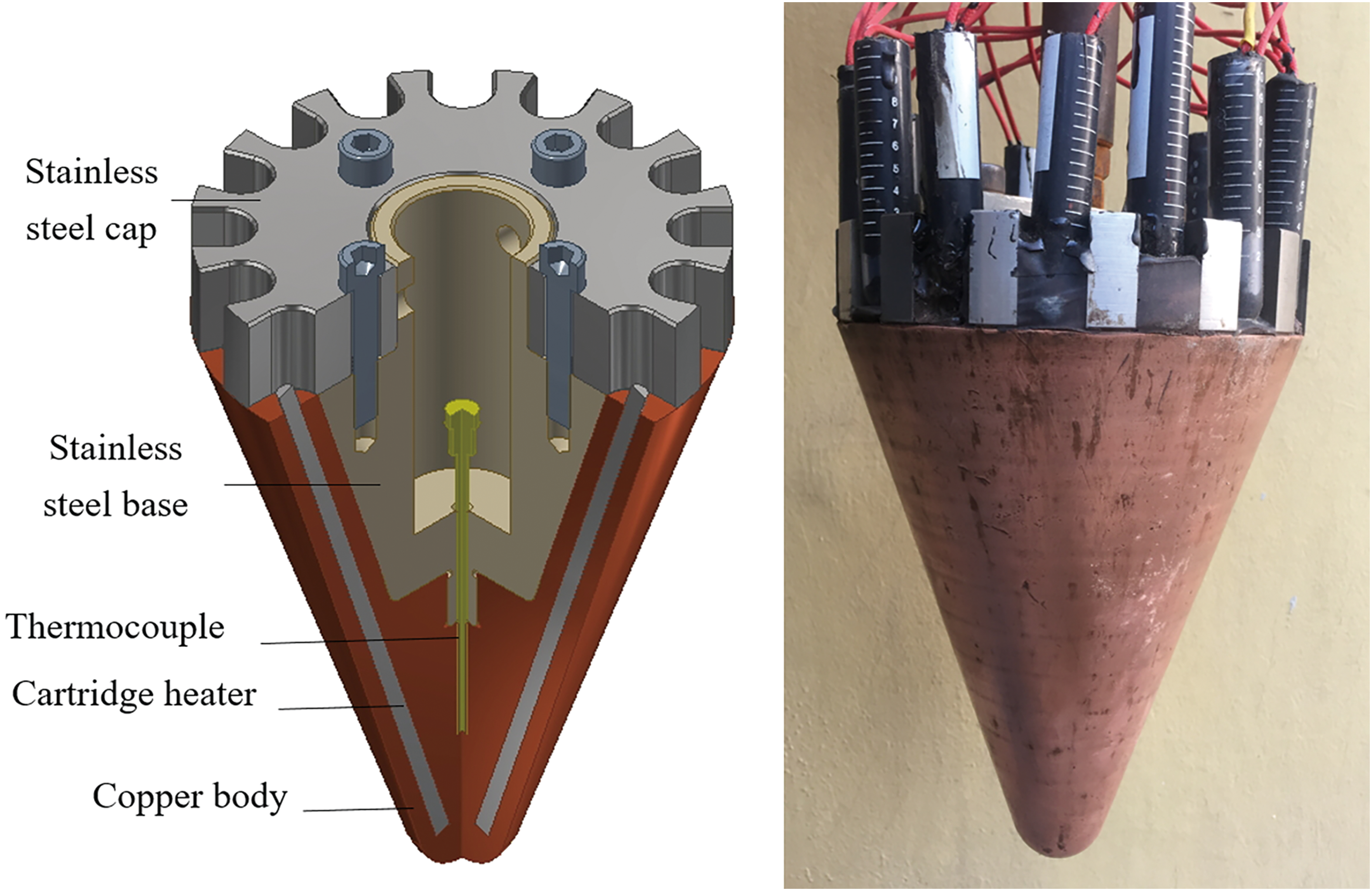
Thermal head prototype with cartridge heaters inserted in holes of copper body. Color images are available online.
Parameters of Cartridge Heaters
Represents good-quality cartridge heaters used by RECoverable Autonomous Sonde thermal heads.
The ends of both cartridge heater types had a 10–20-mm non-heating region. The holes associated with the cartridge heaters were slightly >6 mm in diameter to ensure good thermal contact between the copper body and the heaters. The holes were also 10 mm shorter than the cartridge heaters to facilitate improved end sealing with vulcanized rubber. The total nominal power of the prototype should have been 6320 W when the input voltage was 220 V. However, in practice, the power was ∼5000 W because of the poor production quality of the cartridge heaters. The copper body had a short cone shape with a hemispherical tip. The cone angle of the thermal head prototype was 38°, and the length was ∼200 mm. A thermocouple was installed in the central hole of the copper body to facilitate temperature control. The thermocouple was the same type as that previously used, but with a shorter length. The stainless-steel base was connected to the copper body by threading, whereas the cap was fixed to the stainless-steel base with bolts. Compared with the former prototype, this one was lighter with a mass of 15.8 kg.
Testing in −16.5°C ice yielded improved performance of the thermal head (Table 1). It exhibited a higher ROP, higher efficiency, lower power requirements, and lower weight. Although good drilling performance of this prototype was achieved, the cartridge heaters were occasionally short-circuited, which indicates that the watertight sealing of the cartridge heater must be improved.
2.2.3. RECAS thermal heads
After comparing the drilling performance of the two prototypes, it was evident that RECAS thermal heads should be designed based on the prototype with cartridge heaters. The prototype was improved by using a 15-mm-thick stainless-steel pressure chamber that is able to withstand 30 MPa of water pressure to protect the cartridge heaters from short-circuiting (Fig. 4). The pressure chamber was connected to the copper body with a large nut and a central rod. A total of five fluoro rubber O-rings were used to ensure that the external water did not enter.
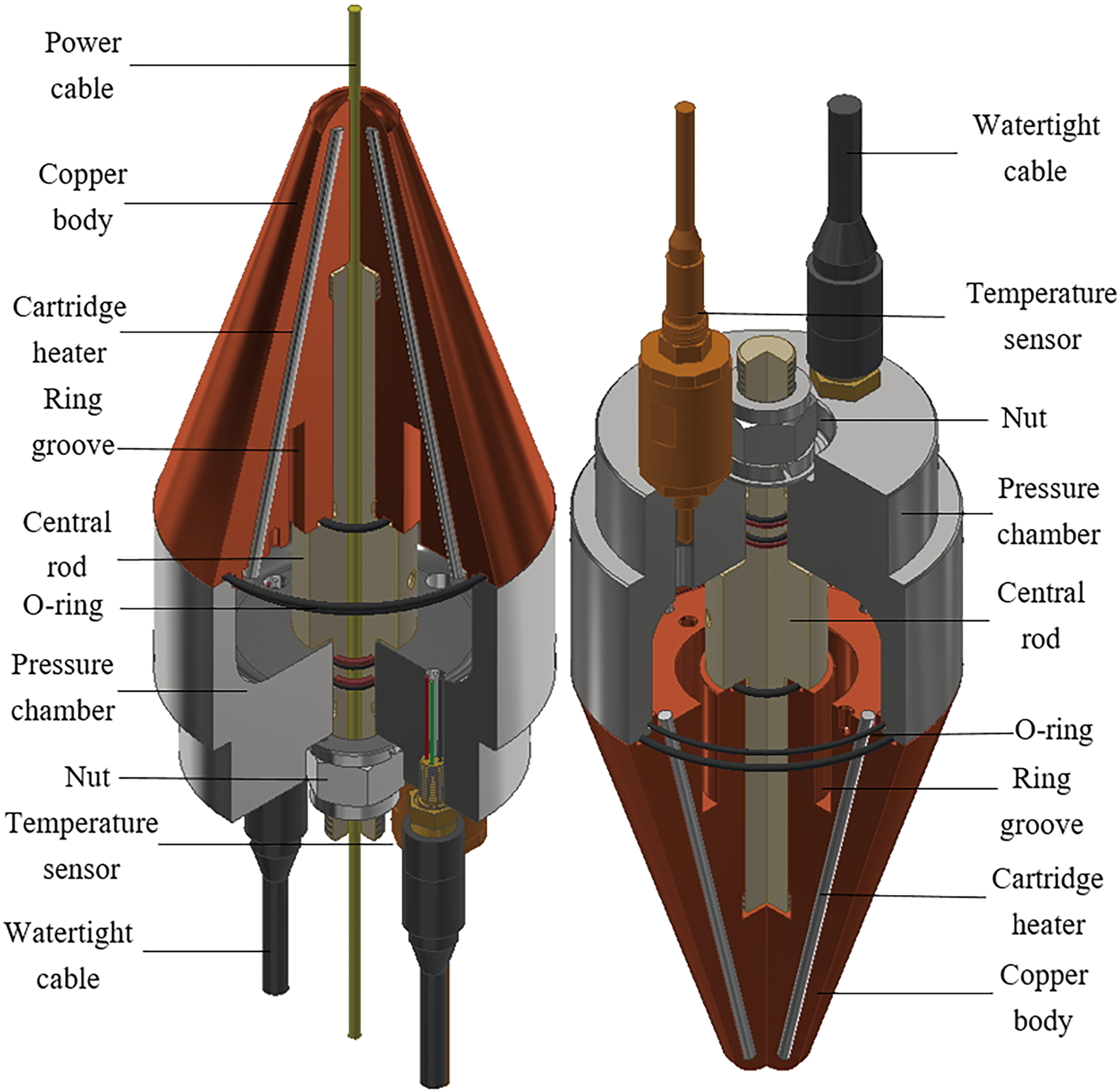
Thermal heads of RECAS: top thermal head (left); bottom thermal head (right). Both thermal heads are shown in working position. Color images are available online.
Initially, a common Pt100 temperature sensor was installed in a hole with a depth of 5 mm in the copper body to monitor the temperature during ice-drilling. It was then replaced by a more sophisticated temperature sensor to improve the temperature signal transmission and control. The Pt100 sensor was 3 mm in diameter, had a length of 10 mm, and can measure temperatures in the range of −50°C to 200°C. The newly used temperature sensor was installed on top of the pressure chamber, to measure temperature in the chamber instead of the copper body. The temperature sensor contains a small temperature probe and a pressure chamber, which can operate at a depth of 3000 m in water with a measurement range of −60°C to +300°C. The temperature probe can measure analog current signals in the range of 4–10 mA. A small circuit board in the pressure chamber of the temperature sensor can convert the measured analog current signals to digital signals and then transmit them to the central control system of RECAS.
The top thermal head uses two small watertight cables, whereas the bottom head uses one cable with a higher current-carrying capacity. High-quality cartridge heaters with power error values <5% produced ∼5 kW of heating at 220 V (Table 2). The customized high-quality cartridge heater is made by WATLOW company in the United States. The diameter and length of the heaters were kept the same size as earlier. In the copper body and the central rod of the top thermal head, there was a hole with a diameter of 7 mm for a strengthened cable that was used for suspending RECAS sonde. This cable supplied all the power required by the sonde. The thermal heads had a length of ∼320 mm, and the copper body was 200 mm long. On the copper body, a 55-mm-deep ring groove (Fig. 4) was designed to prevent the inward transfer of heat. Each thermal head weighed ∼26 kg in air and 19.4 kg in water.
2.3. Testing of the RECAS thermal heads
2.3.1. Testing in clean ice
Both the top and bottom thermal heads were tested in clean ice samples. The ice samples were frozen in a freezer with an adjustable temperature range of 0 to −30°C. Tap water was injected in a large cylindrical steel drum, which was 1 m in length and 45 cm in diameter. The water was then frozen in the freezer for several days until the desired ice temperature was reached. During testing, the simple Pt100 temperature sensor was used to monitor the temperature of the copper body. The top thermal head was tested for drilling downward instead of drilling upward.
To study the influence of the input power on the drilling performance, the RECAS thermal heads were tested in −10°C ice for different power settings. During the drilling process, the axial load was kept constant at 54 N, because it was determined that an increase of the axial load did not result in an increase of the ROP. This will be explained later in the article. The influence of the axial load on the drilling performance of the two thermal heads was also investigated in −10°C ice by using an input power of 5 kW. For thermal head, the ice temperature is also a key factor that influences drilling performance. To study this influence, the bottom thermal head was also tested for −20°C and −30°C ice by using a 5 kW power input.
2.3.2. Testing in dirty ice
During thermal melt drilling in dirty ice, the solid particles (or dust) trapped in the ice will be released to the water. After being suspended in water for some time, some of these particulates may descend to the bottom of the borehole and block the progress of drilling. Accordingly, a dust collector was designed above the thermal head to collect the suspended particles in the melted ice (Fig. 5). The collected particles provide information on the internal material of the ice sheet after the RECAS returns to the surface. The dust collector was a simple stainless-steel tube with four windows to collect solid particles. It had a length of 14 cm and was fixed above the pressure chamber of the bottom thermal head with bolts. Two semicircular covers supported by a hollow rod were designed to prevent solid particles from entering the RECAS sampling system, which was just above the dust collector. The design of the dust collector is similar to the nozzle cup of the BAS hot water drill (Makinson and Anker, 2014).
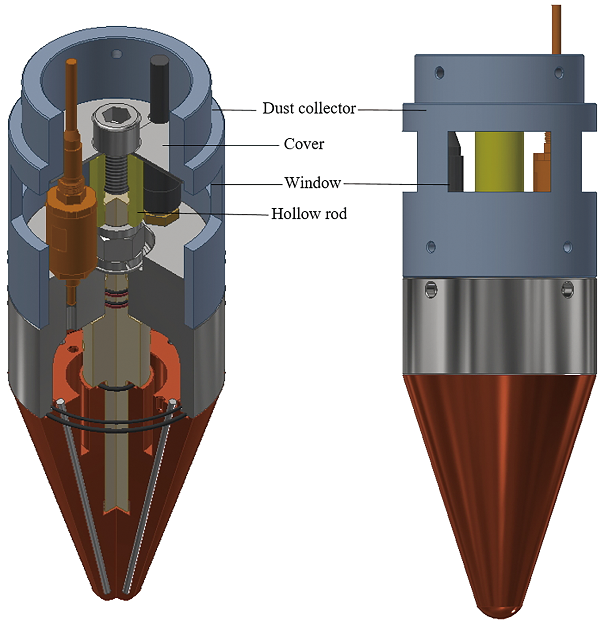
Dust collector above bottom thermal head. Color images are available online.
The bottom thermal head with a dust collector was tested in frozen dirty ice samples (Fig. 6a). The ice samples were made in four steps. First, tap water was added to a specific height in a steel drum, and it was frozen in a cold container. Second, after smoothing the surface of the ice, a pre-sifted fine sand mixed with ice chips was evenly distributed on the ice. Third, tap water was added to the mixture until a 10–25-mm dirty ice layer was formed (Fig. 6b). Finally, tap water was added to fill the steel drum and frozen at −30°C for ∼1 week. Two types of fine sand with different particle sizes were used for the ice samples. One type of fine sand had a particle size <0.2 mm, whereas the other type had particle sizes in the range of 0.2–0.4 mm. For a dirty ice layer, ∼1.5 kg fine sand was mixed with ice chips. The mixing ratio of sand/ice is about 1:2.
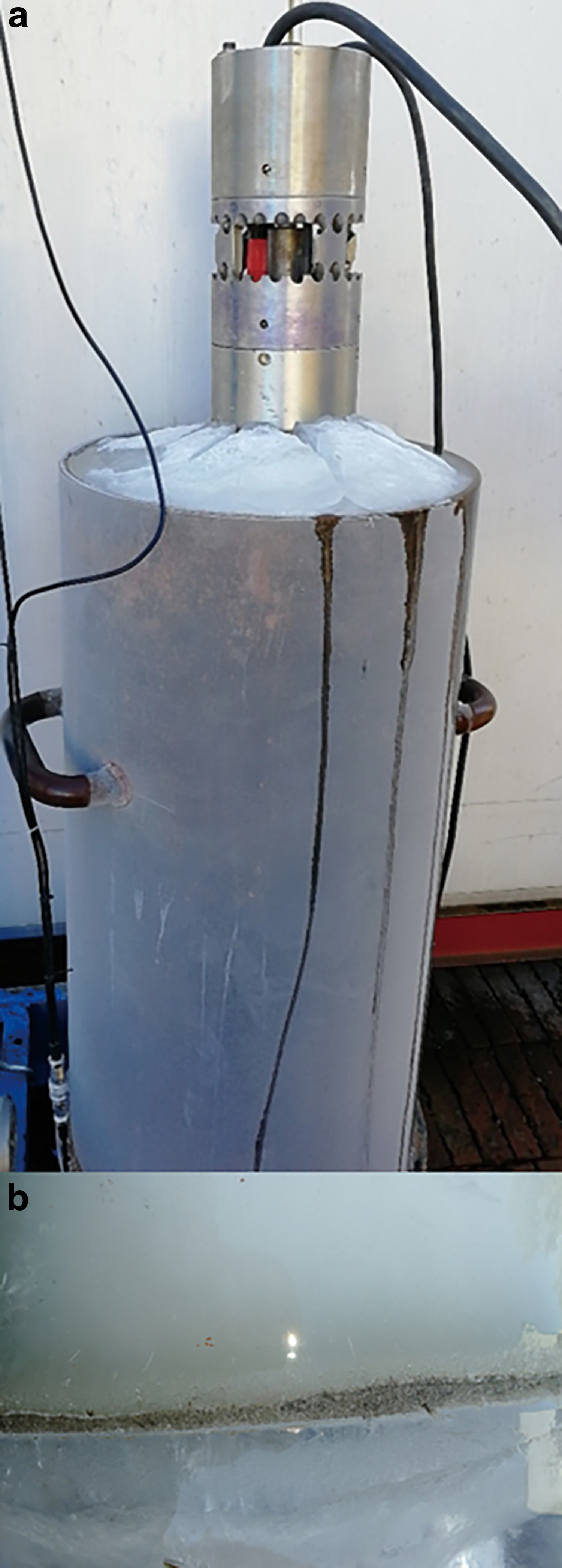
Testing of thermal head in dirty ice.
2.3.3. Lifetime test
To determine whether the RECAS thermal head can work continuously for several months, the top thermal head was powered at 5 kW in a simple water circulation system for 14 days (Fig. 7a). The circulation system contained a heat sink with an air-cooling fan, a UPS-8 centrifugal pump, a water tank, and a controller. The top thermal head was placed in a water tank that was full of cold water, and then a voltage of 220 V was applied by using a number TDGC2-10KVA type single-phase transformer, which had an adjustable output voltage from 0 to 250 V. The transformer is made by Delixi Electric Co., Ltd.
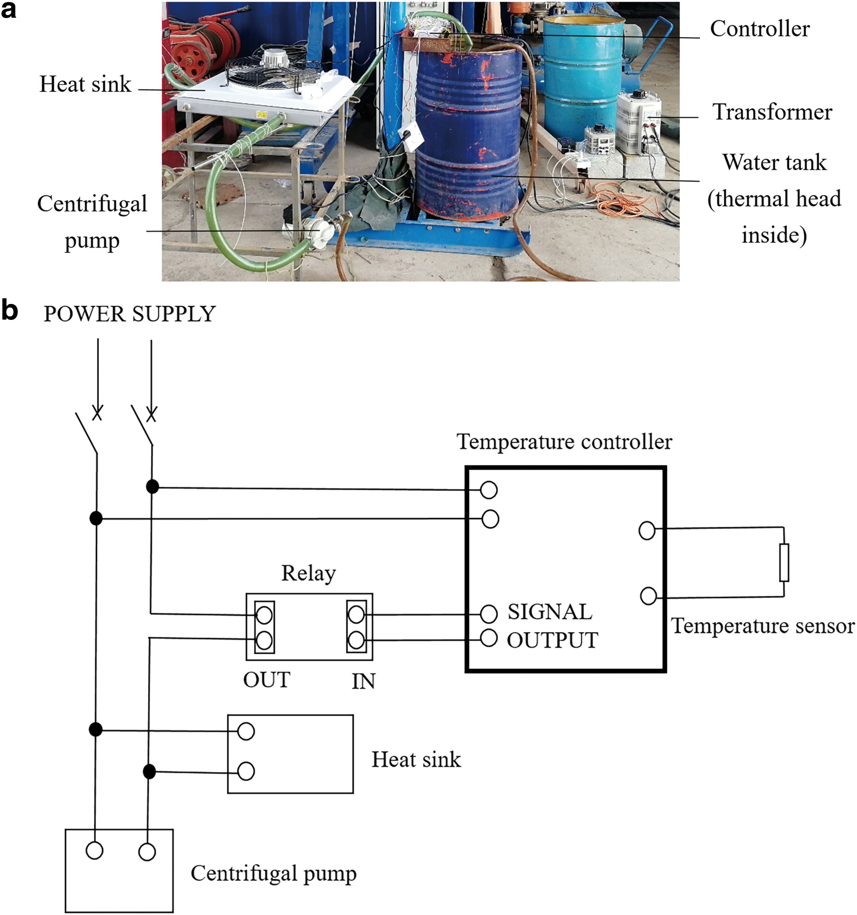
Lifetime test of top thermal head.
The heated water was pumped to a heat sink by using the centrifugal pump to facilitate air cooling before being returned to the water tank. The controller can regulate the start and turn off time points of the heat sink and centrifugal pump by using the Pt100 temperature sensor in the water tank. When the water temperature was >45°C, the heat sink was operated; when the water temperature was <25°C, it turned off automatically. The wiring schematic of the temperature controller is shown in Fig. 7b. The heat sink was made of Al and had dimensions of 600 × 700 × 50 mm. The air-cooling fan was driven by a 180 W AC motor. The centrifugal pump, which was driven by a 165 W motor, kept working to mix cold water and hot water in the water tank at a flow rate of 60 L/min. In the testing process, the resistance of the top thermal head was occasionally measured to check whether all the cartridge heaters worked well.
2.3.4. Temperature measurement of ice near the borehole
To estimate heat losses, it is essential to know how the temperature of ice near the borehole changes during and after drilling. As such, a −25°C clean ice sample and a set of twenty Pt100 temperature sensors were introduced to a steel drum. The temperature sensors were divided into two groups, and each group contained 10 devices. These were named as T01, T02…T20 and symmetrically distributed on the same horizontal plane, which was at a depth of 40 cm from the ice surface (Fig. 8). The central circular area where drilling by the thermal head was planned was free of temperature sensors. Based on the previous tests, the diameter of the circular area was set to be 17.5 cm, and the distance between two adjacent temperature sensors was 1.25 cm. During testing, the bottom thermal head was used for drilling with 5 kW of power.

Temperature sensor distribution in ice sample. The red dots are Pt100 temperature sensors. Color images are available online.
3. Results
3.1. Drilling performance in clean ice
In −10°C ice, the ROP increased linearly with power, and the bottom thermal head could drill faster than the top thermal head (Fig. 9a). This is because the top thermal head has an unheated central hole that slows down the ROP. However, this phenomenon may be eliminated when the top thermal head melts upward, because the hole contains electrical wires instead of ice when melting occurs in the upward direction. A power level of 5 kW ensured that there was a 1.95 m/h ROP to the bottom thermal head and 1.8 m/h ROP to the top thermal head. Therefore, both thermal heads met the design requirements for RECAS.

Influence of input power on:
It is evident that the efficiency of the bottom thermal head decreased from 95% to 78% with an increase in power from 2 to 6 kW (Fig. 9a). This is because more heat is lost as the bottom thermal head temperature is increased from 24°C to 56°C (Fig. 9b). With a 5 kW power input, the bottom thermal head achieved an efficiency of 80.3% and a copper body temperature of 47°C, whereas the top thermal head achieved an efficiency of only 74%, as the copper body temperature increased to 98°C. In general, a lower penetration rate of the top thermal head led to a reduced efficiency of 5%–7% and a self-temperature that was nearly two times higher.
During these tests, an extra Pt100 temperature sensor was fixed above the thermal head. This sensor revealed that the temperature of the melted ice ranged from 7.4°C to 11.4°C. After drilling, the diameter of the drilled hole was measured to be ∼170 to 180 mm.
As shown in Fig. 10a, the ROP increased with the axial load only when it was <20 to 40 N; thereafter, there was minimal change in the ROP. This means that increasing the axial load on the RECAS thermal head has no effect on the ROP. If the axial load is too small, the thermal head will experience poor thermal contact with the surrounding ice, and a significant amount of energy will be lost to heating the water and the thermal head. For example, the drilling efficiency decreased from 83% to 63% when the applied axial load on the bottom thermal head decreased from 33 to 4 N (Fig. 10a). As a result, the temperature of the thermal head increased from 48.4°C to 80.8°C (Fig. 10b).
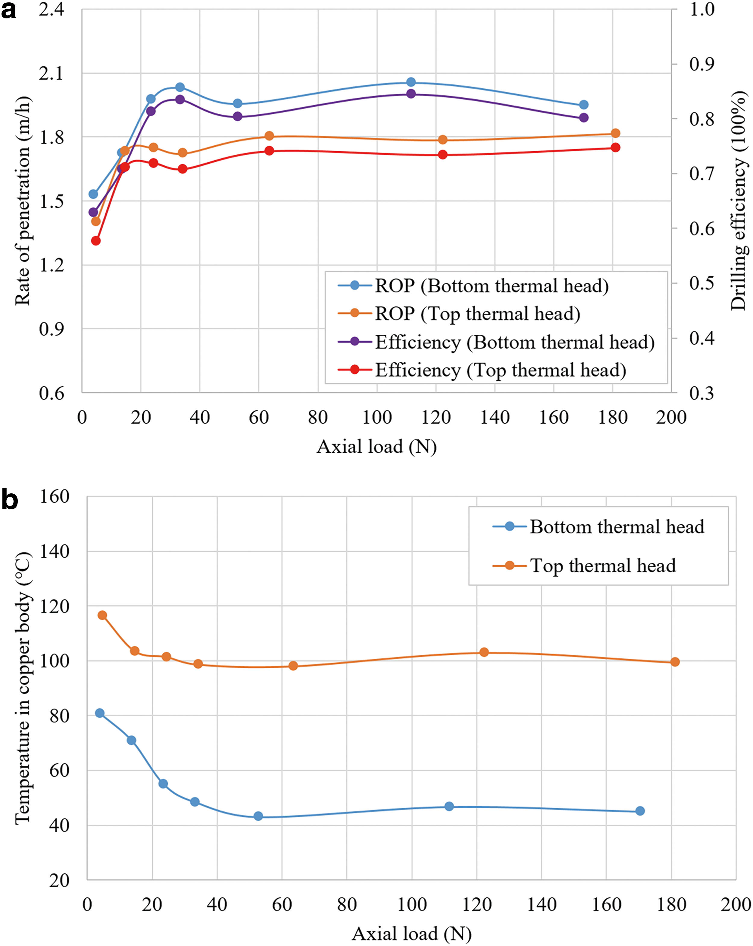
Influence of axial load on:
As shown in Fig. 11a, the influence of ice temperature on ROP was significant. When the temperature of the ice decreased from −10°C to −30°C, the ROP also decreased from 1.95 to 1.62 m/h. The minimum expected ROP of 1.5 m/h required an ice temperature of more than −37°C. Preliminary predictions revealed that the ROP for ice at −60°C was twice as small compared with ice at 0°C. In the Antarctic Ice Sheet, the temperature of ice usually increases from the surface to the bottom; therefore, RECAS will penetrate increasingly faster with an increase in depth. The slower penetration rate in the upper region of the ice sheet could be compensated for by the faster ROP in the lower region. The change law for the temperature of ice and the ROP also indicates that the temperature of the ice sheet can be approximately estimated based on the recorded ROP.
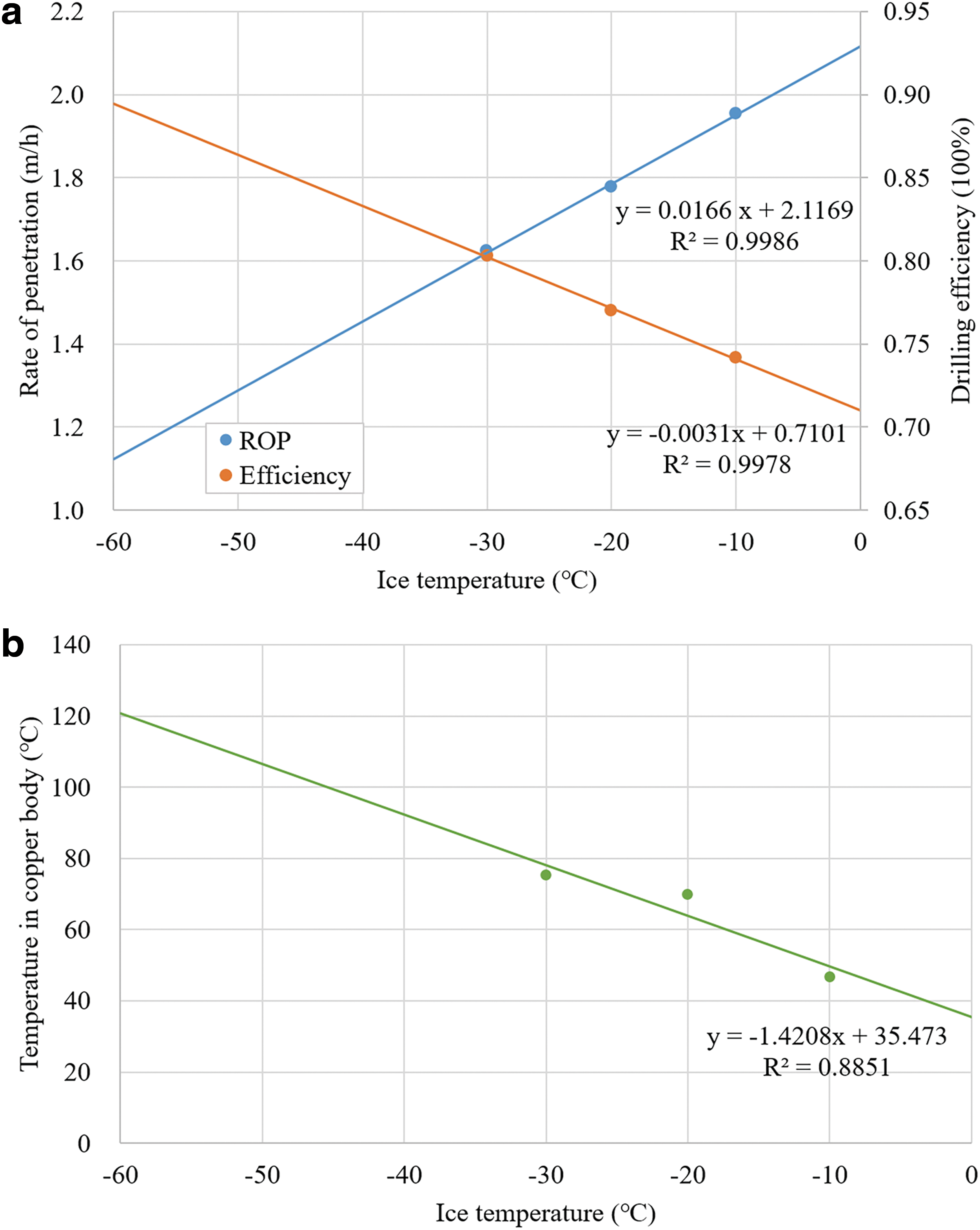
Influence of ice temperature on:
Contrary to the ROP, the efficiency decreased with an increase in the ice temperature. In −60°C ice, the efficiency was nearly 90%, whereas it was only 70% in 0°C ice (Fig. 11a). The ice temperature can also affect the copper body temperature. Increasing the ice temperature from −60°C to 0°C can lead to a decrease in the temperature of >80°C in the copper body of the bottom thermal head (Fig. 11b). To a certain extent, the thermal head temperature can be used to calibrate the ice temperature estimated by using the ROP data if the precise relationship between the ice temperature and the copper body temperature is known.
3.2. Drilling performance in dirty ice
During drilling into dirty ice, a significant quantity of released particles remained suspended in the melted ice, which caused the water to become dark (Fig. 12a). After drilling, although some particles were still suspended in the water, the dust collector successfully collected a thin layer of solid particles or dust (Fig. 12b). We expected that ∼30% of the dust would be collected. The drilled borehole wall was quite smooth, and some heavy particles were deposited at the bottom of the borehole (Fig. 12c).
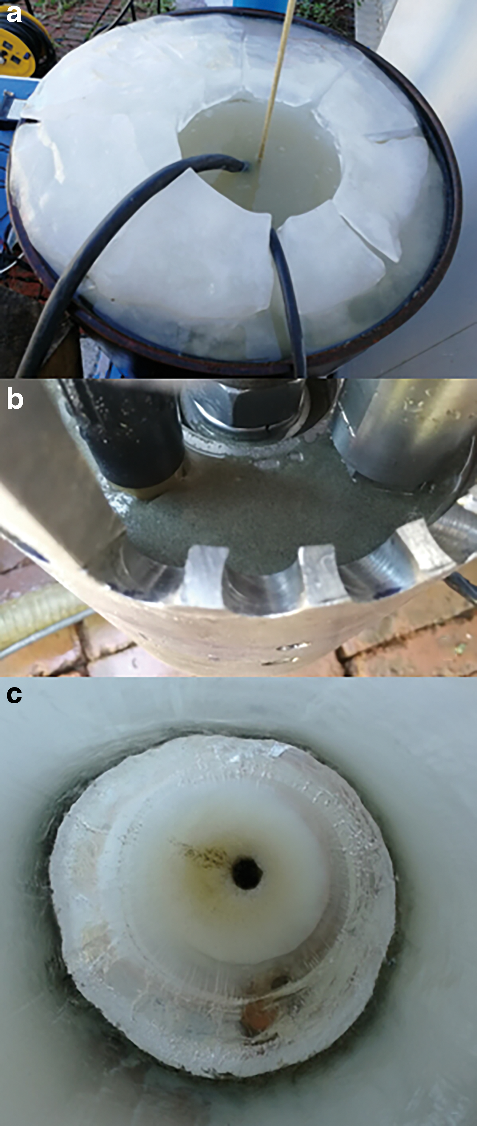
Drilling performance in dirty ice.
The ROP change during drilling for the two ice samples with different types of fine sand is shown in Fig. 13. In the dirty ice sample with the 0–0.2-mm fine sand, the bottom thermal head drilled at an average rate of 1.7 m/h at the beginning, and then the ROP suddenly decreased to 1.2–1.3 m/h when the dirty ice layer was encountered. After the entire thermal head passed through the layer, the ROP increased to 1.5–1.6 m/h, which was slightly lower than the rate for clean ice. This may be caused by the adhesion of the small particles to the outer surface of the thermal head. Drilling in the ice sample with 0.2–0.4 mm fine sand exhibited a similar trend in the ROP. The only difference was that after passing through the dirty layer, the ROP recovered to its original value. Compared with drilling in clean ice, the borehole diameter was 5–10 mm bigger when drilling in dirty ice. Overall, the test results showed that the RECAS thermal head can drill in dirty ice and the proposed dust collector operates effectively.
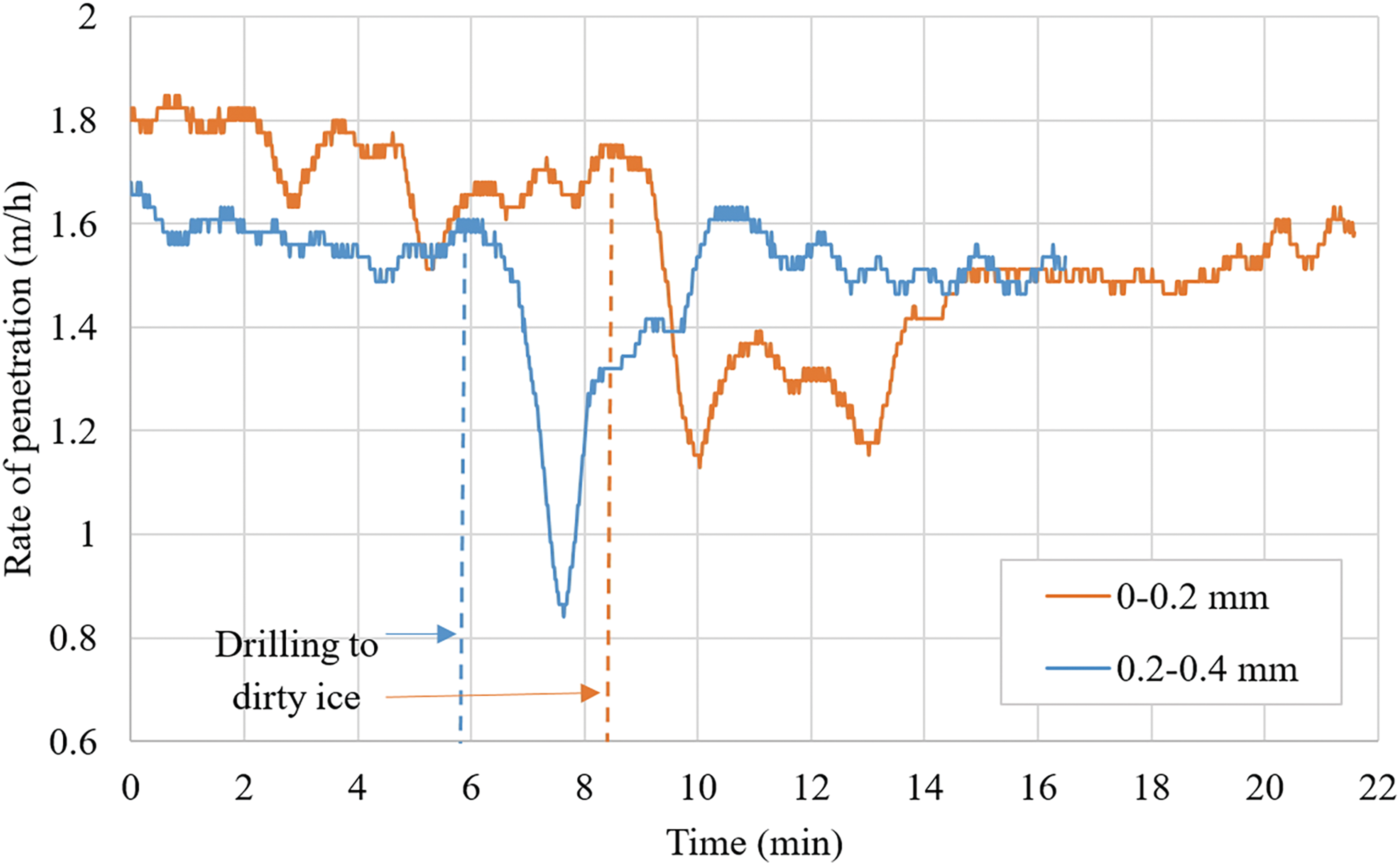
Change of ROP during drilling into dirty ice. The vertical dashed line shows the time that the bottom thermal head drilled into the dirty ice layer. Color images are available online.
3.3. Lifetime of RECAS thermal head
After 14 days of heating in water, none of the cartridge heaters were broken. But the outer surface of the top thermal head was oxidized, which was not ideal for the transfer of heat to the ice. Although the ice sheet does not have much oxygen compared with the circulated water, there is still a risk that oxidization of the thermal head may reduce the penetration rate. Nonetheless, 2 weeks of continuous work without cartridge heater failure or other problems is a good indicator that the RECAS thermal head can successfully drill into subglacial lakes.
3.4. Temperature distribution of ice near the borehole
The temperature change in the first group of temperature sensors (T01, T02…T10) is shown in Fig. 14a. At 11 min after the start of drilling, the bottom thermal head drilled to the plane where the temperature sensors were distributed, and the ice temperature close to the borehole wall increased rapidly. For example, temperature sensors T01 indicated a temperature increase of 15°C in 4 min. The greater the distance away from the borehole wall, the slower the temperature increased. After 20 min, drilling was stopped and the ice sample was returned to the freezer at a temperature of −25°C for another 36 min to observe the temperature change. In the freezer, the temperature of the ice closest to the borehole wall stopped increasing after 10 min and remained at −3°C. In other regions of the ice sample, the temperature continued to increase, even after 36 min in a cold container. T10 showed that the ice temperature increased by at least 6°C for the ice near the steel drum that was 12.5 cm away from the borehole wall (Fig. 14b).
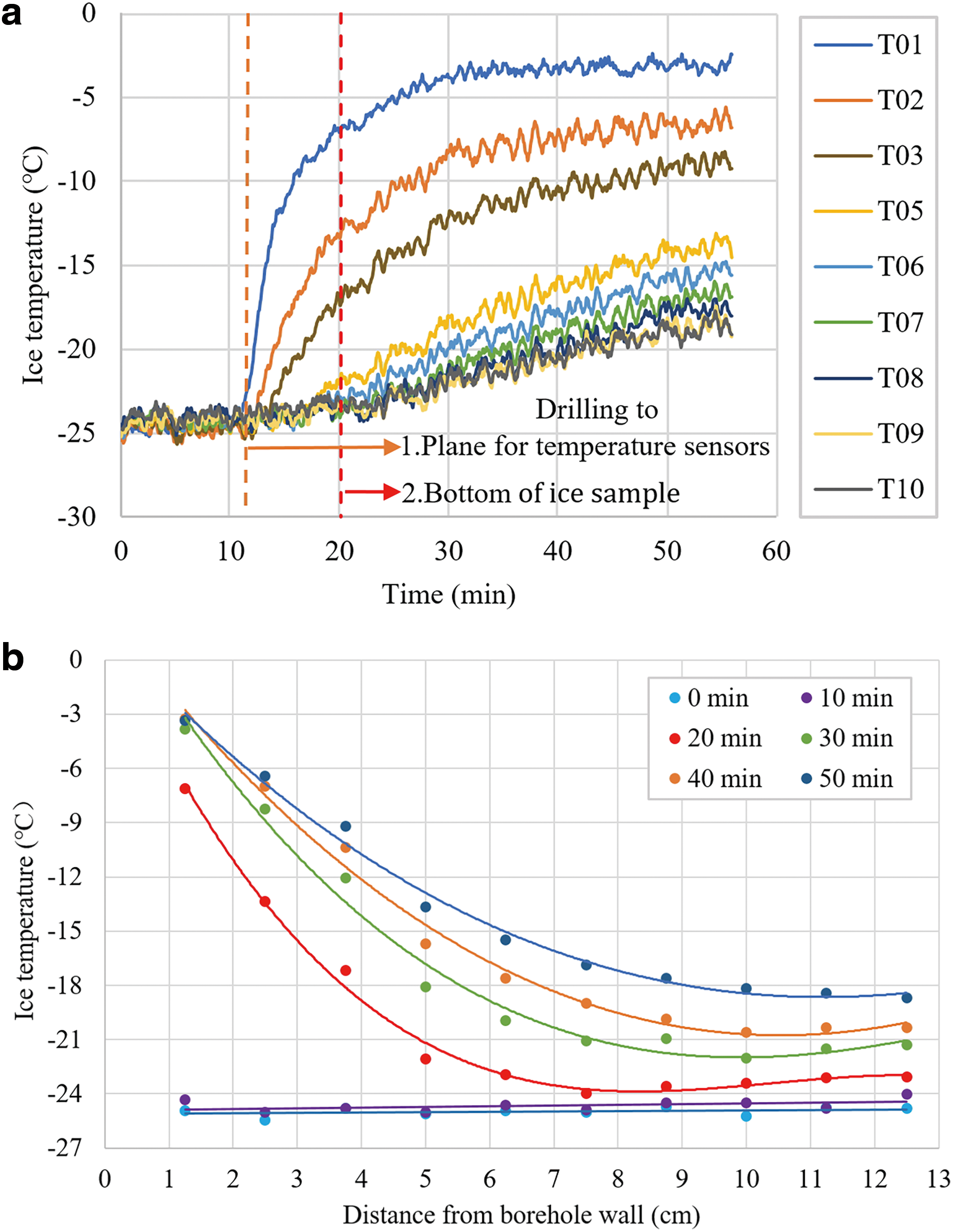
Change of ice temperature with:
It is evident that the influence of thermal head on the temperature of ice becomes smaller with an increase of the distance from the borehole wall. At a specific time, the temperature of the ice >9 cm way from the borehole wall was almost constant. The tests also revealed that at least ∼1 m of the RECAS body above the bottom thermal head will be free, even without the lateral heater in −25°C ice if the power of the drill head is maintained at 5 kW.
4. Discussion
The exploration of subsurface extraterrestrial ice environments on Mars, Europa, Enceladus, and Titan has gained increasing attention in recent years. The main finding from experimental studies was that the penetration performance of classical melting probes under low-pressure conditions can be much less favorable compared with Earth's atmospheric surface pressure. This is mainly due to the absence or intermittent presence of a liquid phase, which can cause poor thermal contact between the probe's hot tip and the surrounding ice. Nevertheless, interest in the scientific and engineering community with respect to the development of hot points for application to planetary missions is still high.
The RECAS thermal probe was designed for exploring subglacial lakes, and it is currently under development at JLU. It can be considered a prototype of a melting probe for planetary applications. The key components, including both the top and bottom thermal heads, were designed and tested. Preliminary lab testing revealed that the thermal heads are well designed and are ready for use in the exploration of subglacial lakes.
The efficiency of the thermal head is highly dependent on its design features, such as the distribution of the heaters, the shape, and the type of material used. The formulas used for the calculation of power consumption of the thermal head are based on an energy conservation equation that neglects the design features of the thermal head. However, theoretical estimates can easily lead to an underestimation of power consumption, because the efficiency coefficient is usually overestimated based on the assumption of a well-designed thermal head. For different designs, the actual efficiency coefficient can be quite different. For example, the efficiency of a thermal head prototype with cable heaters cast in Al is much less than that of a prototype with cartridge heaters inserted in holes. It should be noted that the efficiency of the thermal head can only be determined after testing.
For a well-designed thermal head, the heaters should be distributed as close as possible to its outer surface. The power density in the outer surface of the thermal head should be uniform to avoid cold spots, which can result in a significant waste of energy and enlargement of the borehole. The distribution of the heaters is related to the thermal head shape. Therefore, in the designing process, the distribution of heaters and the thermal head shape should be considered together. To drill subglacial lakes, good-quality heaters with low power errors and long lifetimes should be used. If cartridge heaters are used, the associated holes must be manufactured precisely.
The penetration rate of a thermal head is basically determined by the input power. For the RECAS thermal head, the ROP increased linearly with power, whereas the efficiency decreased linearly. A decrease of the efficiency leads to an increase in temperature in the thermal head and melted ice. The axial load on the thermal head has a very small influence on the ROP when it exceeds a specific threshold value. In our case, this was ∼30 N, or a corresponding pressure of 1.5 kPa. The increase of the axial load does not improve drilling performance. However, the ice temperature significantly affects the ROP of the thermal head. As expected, the ROP decreased with a reduction of the ice temperature.
Although a slight decrease in the ROP was observed when drilling in dirty ice, the thermal head can drill through tephra layers in the ice sheet. This was also recently confirmed by Kömle et al. (2018b). This is because the released solid particles or dust can be flushed out from the bottom of the thermal head by water convection. Our simple collector can partially collect the suspended solid particles during drilling. More attention should be focused on the oxidation of the thermal head that occurs during long-term operation in water. Covering the outer surface of the thermal head with materials that prevent oxidization and have high thermal conductivity may be a good solution. The heat disturbance range caused by the RECAS thermal head has no clear mathematical approximation, and more research must be conducted to better understand the relationship between ice temperature, input power, and heat disturbance range.
In this work, more attention was paid on feasibility of the thermal heads to melt ice and the top thermal head was only tested in forward direction. In the future, trajectory control of RECAS thermal probe must be considered when drilling downward and upward. In addition, it is very important that the top thermal head can melt back to the ice surface with a good inner winch system. Now, the prototype of the inner winch system has been manufactured and preliminary tests showed its excellent design. Soon, a complete RECAS thermal probe with all its parts connected together will be tested in a JLU ice well and then in the field.
Footnotes
Acknowledgments
The authors would like to thank undergraduate students Chang Liu, Taotao Cheng and the postgraduates of the Polar Research Center of Jilin University for their help in preparing the experiments.
Author Disclosure Statement
No competing financial interests exist.
Funding Information
This research is supported by the Ministry of Science and Technology of the People's Republic of China (Project No. 2016YFC1400300), the National Nature Science Foundation of China (Project No. 41706214), and the Program for Jilin University Science and Technology Innovative Research Team (Project No. 2017TD-24).
Associate Editor: Christopher McKay