
Abstract
Abstract
The topic of this article is the development of an open-source automated design framework for synthetic biology, specifically for the design of artificial gene regulatory networks based on a digital approach. In opposition to other tools, GeNeDA is an open-source online software based on existing tools used in microelectronics that have proven their efficiency over the last 30 years. The complete framework is composed of a computation core directly adapted from an Electronic Design Automation tool, input and output interfaces, a library of elementary parts that can be achieved with gene regulatory networks, and an interface with an electrical circuit simulator. Each of these modules is an extension of microelectronics tools and concepts: ODIN II, ABC, the Verilog language, SPICE simulator, and SystemC-AMS. GeNeDA is first validated on a benchmark of several combinatorial circuits. The results highlight the importance of the part library. Then, this framework is used for the design of a sequential circuit including a biological state machine.
1. Introduction
F
Up to now, the theoretical knowledge and technological know-how in this field led to the development of reprogrammed micro-organisms with only few artificial functions. The design process is mainly hand-made, and tools, techniques, and DNA parts are mostly developed in a specific context that limits their reusability. The needs for standardization to overcome this shortcoming arose at the end of last decade. Standardization involves several work packages (Canton et al., 2008). One is the development of a set of reusable artificial DNA strands, performing elementary biological functions uncoupled from each other and from their environment, which can be assembled as Lego® bricks in order to design a context-free complex function (Knight, 2003).
Aside from this more technology-oriented topic, standardization paves the way for the development of computer-aided workflows for the in silico design and prototyping of artificial GRN. Such a tool is often called Genetic Design Automation (GDA) (Hassoun, 2012; Lux et al., 2012; Myers et al., 2009) by comparison to Electronic Design Automation (EDA), which involves software, languages, and methodologies for the design of very large-scale integrated electronic circuits (Gerez, 1999; Wang et al., 2009). The comparison between GDA and EDA can even be extended beyond the principle of the tool. Indeed, it was demonstrated at the very end of the last century that functional analogies exist between GRN and electronic circuits, especially at the Boolean level of abstraction (Knight and Sussman, 1998; Weiss et al., 1998; 2002). Thus, several concepts used in EDAs for the automated design of digital circuits could be reengineered to be used in the GDA.
Several Computer-Aided Design (CAD) tools for artificial GRN have already been developed around the concept of reusable genetic parts (Knight, 2003). For instance, GenoCAD (Czar et al., 2009), BioJADE (Goler, 2004), or TinkerCell (Chandran et al., 2009) can be used to virtually assemble parts picked up in a library and simulate a complete GRN. Several aspects of the design process are semi-automated, such as the research of parts in the library according to some criterions (function, performances, or compatibility rules). In comparison, there are far fewer tools addressing the upstream issue (i.e., the automation of parts selection derived from a high-level specification).
Several successful breakthroughs, confined to the Boolean abstraction of GRN, deserve to be highlighted. TASBE, developed by the Massachusetts Institute of Technology and Boston University, is one of them (Beal et al., 2011b; 2012). It consists in a tool-suite (including several new or existing tools such as Proto, BioCompiler, MatchMaker, and BiOCAD) that starts from high-level specifications given in a specific language and leads to DNA assembly that meets the requirements. The upstream stages of TASBE include the high-level description and “Bio-compilation” (interpretation of the high-level description as a set of elementary biological functions) (Beal et al., 2011a; Bilitchenko et al., 2011; Densmore et al., 2010; Yaman et al., 2012). Another interesting approach, also based on Boolean abstraction of GRN, has been suggested by Marchisio and Stelling (2011).
The problematic design automation for GRN at the Boolean level of abstraction is very similar to the one tackled by design automation used in digital microelectronics (Wang et al., 2009). It is therefore reasonable to think of the opportunity to adapt electronic digital synthesizers (“digital synthesis” is the ad hoc term used in electronic context for the design automation of digital circuits) to the synthetic biology features rather than redeveloping new tools. This approach is developed in this article. The first section is an introduction to the main concepts of design automation for digital electronics. Then, the workflow of GeNeDA software is described. The next section is devoted to the results obtained on a workbench of combinatorial circuits as well as on a complex sequential system. Methods and Results are then discussed in the last section. Several terms from microelectronics jargon are used in this article. All of them are explained briefly in the plain text of the paper and with more details in a glossary given as Supporting Information.
2. Design Automation for Digital Electronics
The automation of the design of electronic circuits from a high-level specification has been a very active area of research since the very beginning of microelectronics history in the 1960's. From the outset, separated ways have been investigated for analog circuits and for digital circuits. Analog circuits are usually described by their transfer function, analytic equations, or a set of coupled ordinary differential equations. Despite some breakthroughs in the end of the 1990's, the development of a generic fully automated analog synthesis tool is still an open field of investigation (Ismail and Franca, 2012; Jerke and Lienig, 2009; Koza et al., 1997; Rutenbar, 1993). Until now, CAD tools in analog context are helpful for the designer but are not automated. On the other hand, design automation of digital circuits is a common practice since the early 1980’s (Brayton et al., 1996; Micheli, 1994; Rabaey et al., 2002). Nowadays, several design automation tools exist and are integrated to high-performance commercial software suites (e.g., RTL Encounter of Cadence© tool suite or Design Complier for Synopsis©), which can carry out the synthesis of circuits with hundreds of thousands of logic gates. In addition, several open-source tools developed by academics also exist.
Basically, design automation of digital circuits is a three-stage process that requires a formal description (high-level specification) of the system we would like to design and a toolbox (design kit) with the elementary functions (parts) that can be achieved with a given technology. The high-level specification is usually given through a description written in hardware description languages (HDL), such as VHDL (Ashenden, 2010) or Verilog (Thomas and Moorby, 2002). For example, the HDL description of a counter is a memory device that is incremented at each rising edge of a clock signal. At this level, the description can be purely behavioral and does not involves any clue about how it will be performed.
The first stage of the process is called digital synthesis. The high-level specification is interpreted and converted into an interconnection of Boolean functions (gate) and memories (registers). This level of description is called register transfer level (or RTL netlist). This step involves syntax analysis and Boolean computation. The design kit comes into play in the second step and contains all the Boolean functions that can be achieved with a given technology. A tool, namely the silicon compiler, finds the combination of parts from the design kit that is equivalent (from a Boolean viewpoint) to the RTL netlist while minimizing a user-defined cost function. After this step, the circuit is designed. For the third step, a complete model of the circuits, generated and fed with information from the design kit, is generated and simulated. The results are compared to the high-level specification in order to validate in silico the circuit before manufacturing. The complete design flow is summarized on Figure 1.
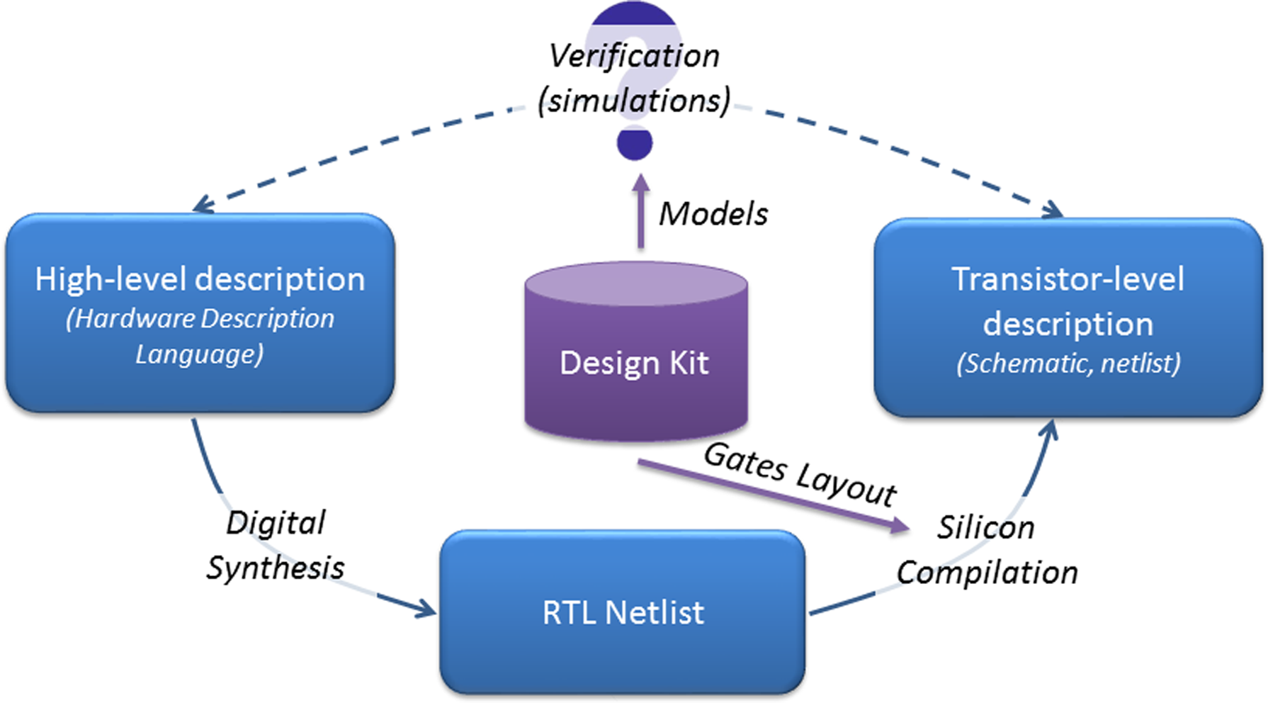
Automated workflow for the design of electronic digital circuits.
Among others, two open-source tools catch our interest because of their relative simplicity and accessibility: Odin II (Jamieson et al., 2010), which is a digital synthesizer developed by the University of Miami, and ABC (Mishchenko, 2015), which is a silicon compiler developed by the University of Berkeley for the configuration of field-programmable gate array (FPGA). In the following section, we will describe how these tools have been reused, adapted, and plugged into an automated design workflow for GRN.
3. Description of GeNeDA Workflow
The GeNeDA framework is described in Figure 2. It is composed of six parts: the input interface (1), the digital synthesizer ODIN II (2), and the GRN compiler ABC (3), a library of elementary mechanisms (parts) used in GRN (4), an output interface (5), and analog and mixed simulator features (6). These parts are described in more detail in the following section.
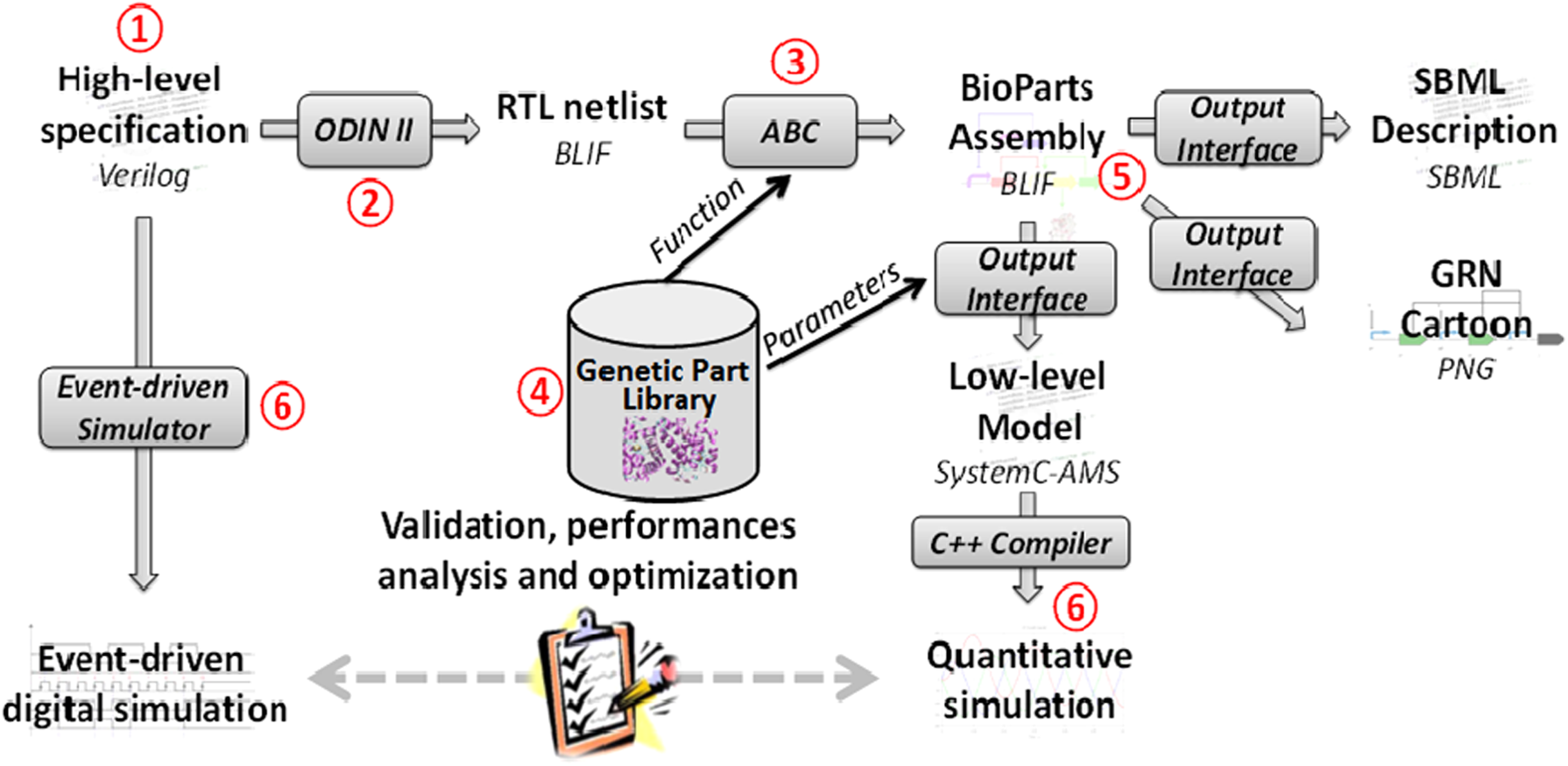
Description of the GRN synthesizer.
3.1. The input interface
ODIN II requires a high-level specification provided in Verilog (Thomas and Moorby, 2002) or Berkeley Logic Interchange Format (BLIF) languages. The input interface bridges the gap between those specific languages and most common ways to describe a combinatorial digital system, such as a truth table or a set of Boolean equations. An online PHP script converts the specification given through a graphical user interface into a single Verilog file.
3.2. The digital synthesizer (Odin II)
ODIN II converts the provided (or generated) Verilog file into a RTL netlist. As for microelectronics, this operation involves only syntax analysis and mathematical manipulations of Boolean equations. This operation does not depend on the technology (silicon or gene regulatory networks) used to perform the function. As a consequence, Odin II can be integrated directly to the framework without modification. Odin II provides the RTL netlist in a standard BLIF file.
3.3. The GRN compiler (ABC)
ABC maps the RTL netlist on a specific technology, GRN in this case. ABC uses a BLIF file provided by ODIN II and is strongly linked to a Genetic Part Library (GPL) described below. ABC computes a combination of GPL elements that achieves the targeted function in an optimal way. The two main performance criterions that are estimated are the cost of the system (computed as the sum of the cost for each instantiated part) and the delay of the critical path (longest time separating an input and output changes). The results are returned as a netlist giving the instantiated parts and their connections.
Several adaptations have been made on ABC in order to fit to biology requirements. One of the trickiest issues concerns the differentiation between activators and repressors, which does not exist in microelectronics. This is based on the assumption that a protein cannot carry out both the role of activator on one promoter and repressor on another one. ABC checks whether this case occurs on the suggested GRN and solves this problem by inserting a second gene (one coding for an activator and one for a repressor) on a construct for which the synthesized regulating protein has to play both roles. Should this occur on an input of the system, an additional buffer (inducible promoter without repressor) is implemented with two protein coding sequences, one for an activator and one for a repressor. This increases the complexity of the system and, as a consequence, should be taken into account in the cost of the construction.
The remaining adjustments of ABC to biological context have been made directly in the genetic part library.
3.4. The genetic part library (GPL)
The GPL includes all the genetic mechanisms that may be involved in a GRN. The library should be written according to a proprietary GENLIB format. The GENLIB file contains one entry per part and, for each of them, the cost of the part, its Boolean function, and a list of inputs. For each input, the following electrical parameters are provided: the phase (inverting or non-inverting), the input load, the max load, the rise and fall block delay, and the rise and fall block fan-out. GeNeDA involves a default library described below and a GENLIB generator allowing to define a subset of the default library.
3.4.1. Minimal library and default library
To be consistent and usable by ABC, a GPL has to contain, at least, a Universal Set of Boolean Operators (USBO) and a synchronous memory (Horowitz and Hill, 1989). In the GRN context, the smallest USBO is a construct with an inducible promoter that can be activated by a protein A or repressed by a protein R. This construct achieves the Boolean “inhibition” operator (A INH R = A AND NOT R). Indeed, by cascading several instances of such constructs, any combinatorial Boolean function can be achieved. However, it is also possible to enrich the GPL with more complex functions, for instance, as a promoter driven by more than one activator or more than one repressor (Fig. 3A), cascaded constructs achieving advanced Boolean functions (multiplexer, encoder …), or constructs involving alternative mechanisms (e.g., a binding reaction between transcription factors or mRNA) such as Moon's AND gate (Moon et al., 2012) depicted in Figure 3B.
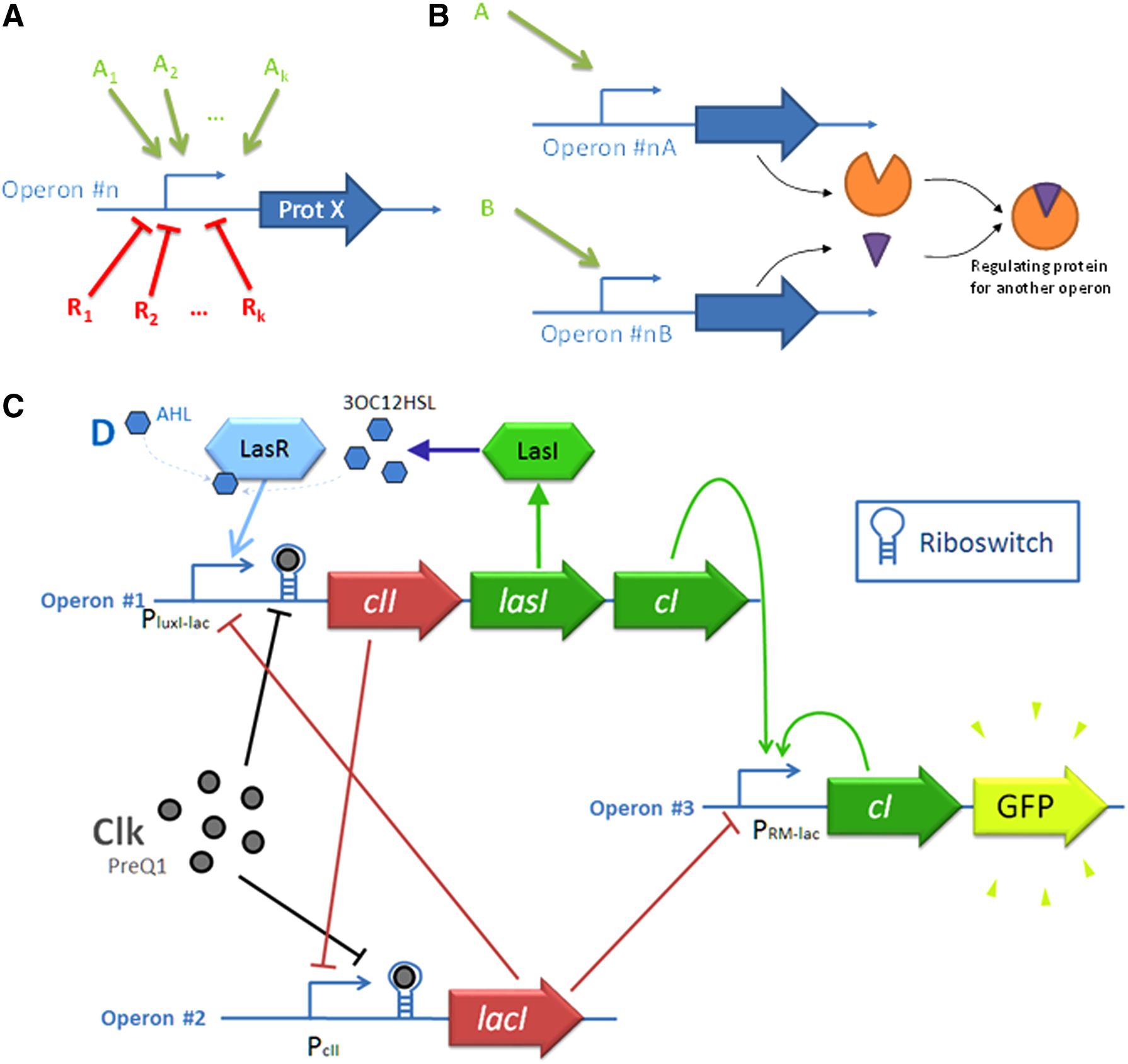
Description of the BPL, which contains the basic functions that can be realized with GRN:
The design of a biological memory is a tricky challenge. The first artificial biosystems exhibiting a non-combinatorial feature are oscillators that switch from a state to another at defined regular time steps (Elowitz and Leibler, 2000) and a toggle switch (Gardner et al., 2000). Alternative constructs have also been described, most of them being based on a positive feedback loop in order to maintain state without external stimulus (Becskei et al., 2001; Chang et al., 2010). All of these solutions are asynchronous (the memory can be updated at any time) and cannot be used in the GPL. Hoteit et al. (2012) suggested a GRN achieving a D-flip-flop behavior. The solution is very expensive (7 promoters and about 10 involved proteins). Recently, a more compact implementation using only 3 promoters and a competitive cross-repression has been proposed and validated in silico (Rosati et al., 2015). It is depicted in Figure 3C.
The default library of GeNeDA includes all the Boolean functions that can be achieved with a promoter regulated by a combination of up to four activators or repressors, the AND and NAND functions realized according to Moon's principle and the biological D-flipflop described above.
3.4.2. Cost of the part
The cost of a part reflects the difficulty to construct an actual system (promoter, regulatory sequence, protein coding sequence) that uses this part. In the default library, costs have been affected to Boolean functions according to the following assumptions:
• It is more complex to add the n + 1-th regulating protein on a promoter than adding the n-th. As a consequence, the relationship between the cost and the number of regulating proteins is a power law. • In general, for a given promoter, it is easier to find a repressor than an activator. As a consequence, for an equivalent number of regulating proteins, a Boolean function involving promoter activation should be penalized in comparison with a function involving promoter repression.
The mathematical law that has been used to take these two facts into account in the cost of each part is the following:
where A and R are, respectively, the number of activator and repressor.
3.4.3. Input and output parameters
The phase parameter is specific in electronics and is not used in biological context. Nevertheless, we use this entry to specify the sign of the regulation (activation or repression). This information is processed by an ABC add-on that we developed to tackle the problem of proteins that carry both the role of activator and repressor, as described in the previous section. Rise and fall delays are used both for timing consideration during simulation, as well as for the computation of the critical path of the system. Rise and fall delays can be defined by the same way in biology and in electronics. It should be noticed that, as opposed to electronics, constant time of the biological phenomena involved in rise (gene expression) and fall process (self or forced decay) may be very different.
Input load and fan out are also important characteristics of a digital gate for which an analogy can be found in biology. Let X be a regulating protein synthesized by the gene #0 and which represses (or activates) N other promoters. If N is too large, there might not be enough proteins to have an effective repression (or activation) of all the promoters. In this context, the input load can be seen as the number of proteins required to repress a promoter efficiently and the fan out as the maximum number of protein that a gene can synthesize. The GRN compiler ensures that, for each protein, the fan out is always greater than the sum of the input load of the promoter it regulates.
3.5. The output interface
The raw output of ABC tool is a C-structure that contains all the information about the circuit (input, output, part instances, connections…). Several add-ons have also been developed in order to provide descriptions that can be taken in charge by simulators. Until now, four formats are supported:
• a BLIF file (i.e., a text file giving the name of the instantiated part as well as the regulation between parts) • a graphical representation of the GRN in PNG format generated by the online design visualizer Pigeon CAD (Bhatia and Densmore, 2013) • an SBML model (standard for the description in system's biology (Hucka et al., 2003)) • SystemC-AMS files (Vachoux et al., 2003), an open source C++ library used for the description and the simulation of heterogeneous systems such as GRN (Pêcheux et al., 2010).
The two last outputs involve a model of the system based on the following five generic equations (Welch et al., 2009):
Equations (2) and (3) give the activation (resp. the repression) term of the promoter with N activators (resp. M repressors). It depends on two parameters per transcription factor:
Parameters as well as their default value for model generation are summarized in Table 1 (Alon, 2006).
3.6. Simulation
GeNeDA does not include embedded simulation features. Nevertheless, the input and output interfaces provide models that may be used with third-party tools. At one end of the workflow, the Verilog file obtained with the input interface can be used in event-driven simulators in order to check the consistency of the input specification. At the other end, the output interface provides a SBML model that can be simulated directly with COPASI (Hoops et al., 2006). An alternative simulation feature (powerful but unusual for the biology community) is SystemC-AMS. This feature manages several Models of Computation (MoC), namely nonconservative Timed Data Flow (TDF), or conservative Electrical Linear Networks (ELN). With this language, the model is written in C++ and, as such, it has been designed to interact freely with other MoCs (i.e., Discrete Event of SystemC) as well as common C++ libraries (Cublas, FFT, access to databases, etc) (Pêcheux et al., 2010).
4. Results
GeNeDA workflow has been illustrated and validated on several standard circuits used in digital microelectronics.
4.1. A benchmark of combinatorial functions
This first section describes the results obtained by GeNeDA over a benchmark of standard digital circuits used in microelectronics. Eight of them (namely a 2-input AND, 4-input AND, 4-input NOR, 2-input XOR, 4-input XOR, 1-bit half adder, 1-bit full adder, and 8-bit comparator) are used to make the emphasis on the importance of the GPL.
Five different GPLs have been investigated. The simplest (GPL0) contains only one inverter (INV) and one inhibition operator (INH). GPL1 is enriched with constitutive promoters that can be inhibited by two repressors (leading to a 2-input NOR behavior or NOR2) or a promoter that can be induced by two activators (2-input OR gate, or OR2). GPL2 is enriched with 2-input AND and NAND gates designed according to Moon's construct (Moon et al., 2012). GPL3 involves GPL1’s function, as well as promoters that can be regulated by three transcription factors: 3-input OR (3 activators, OR3), 3-input NOR (3 repressors, NOR3) but also Boolean function that corresponds to 2 activators and 1 repressor (INH2A1R), and 1 activator and 2 repressors (INH1A2R). Finally, GPL4 involves all the Boolean functions that can be achieved with a promoter regulated by four transcription factors: OR4, NOR3, INH3A1R, INH2A2R, and INH1A3R.
A deeper description of the libraries as well as the complete results are given in Supplementary Information (supplementary material is available online at www.liebertpub.com/cmb). In this part, focus is put on a 4-input AND gate. The GRN obtained for this gate with different libraries is depicted in Figure 4 and the instantiated parts and the GRN performances are shown in Table 2. In GPL0, the synthesizer uses only an inverter (INV), which is a constitutive promoter that can be repressed and an inhibition gate (INH).

Results of the synthesis of a 4-input AND gate with 4 different GPL.
The results involve six promoters and a delay of four (i.e., the critical path, D-n7-n8-n9-GFP, involves four promoters, each of them introducing a delay of one). In other words, when D switches from one state to another, the expression of four promoters have to change sequentially in order to observe the switch of GFP at the output. In GLP1, 2-activators and 2-repressors promoters are integrated. By this way, the critical path can be reduced by using an OR-gate instead of an INH-gate, despite of a 6% extra cost. With GPL3, a 1-activator 2-repressor promoter can be used instead of one OR and one INH. By this means, the system improves both characteristics: the delay is reduced to 2 and the cost to 8.5. Finally, the 4-input NOR gate of GPL4 makes the system less expensive. This last solution corresponds to the one that can be obtained theoretically by applying de Morgan's theorem: A and B and C and D = not( not(A) or not(B) or not(C) or not(D) ).
The main conclusions on this study on combinatorial circuits that deserve to be highlighted are the following:
• As expected, the complex (and thus expensive) parts added into library GPL3 and GPL4 are used sparingly in the designs. • The AND gate designed by Moon's construct is never used by the synthesizer. This is explained by the cost affected to this construct (4.0), which is too high in comparison with other constructs. • For the very simple Boolean function, the use of complex parts on the same promoter does not bring remarkable improvement with respect to the cost or the circuit delay. • For more complex functions, GPL3 and GPL4 leads to important cost or delay reductions. For instance, 25% of cost and delay reduction for the 8-bit comparator between BioLib1 and BioLib4.
Complete synthesis results are given in Supplementary Information.
4.2. Advanced synchronous circuit
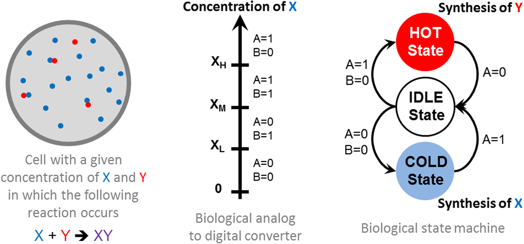
Now, let us consider a more complex circuit involving a sequential subsystem. For this part, we will take and adapt a conventional digital electronic exercise, namely a 3-states regulation problem, to the biological context. Regardless of the field, a regulation problem (thermal regulation, in vivo chemical regulation, as for instance insulin or cortisol) can be tackled with two approaches. One, called analog regulation, consists of a continuous measurement of a species concentration and the continuous control of a flux of this species through a feed-back loop. The other, called digital, is an on/off control of species flux source if the concentration is above or below a threshold. A more subtle digital regulation consists of using a finite state machine (FSM, or automata or sequencer). This FSM could switch between three states and is sensitive to the concentration of an input protein X according to three thresholds: XH, XM, and XL.
Two Boolean inputs A and B are used to identify the right concentration interval (Fig. 5A). After initialization, the system is in the idle state. It switches to the hot state when X > XH and returns to idle state when X < XM. Similarly, it switches to cold state when X < XL and switches back to idle state when X > XM. In cold state, there is not enough of species X and a synthesis mechanism is turned on. In hot state, there is too much X in the cell, another protein Y that consumes X is synthesized. The system is depicted in Figure 4. In this example, only the digital part (i.e., the biological Finite State Machine (BioFSM)) will be considered.
Specification of the BioFSM for the regulation of a given protein. The behavioral description of the system is a state graph describing the state machine.
The starting point of the process, at the input interface, is a Verilog description of this BioFSM (given in Supplementary Information). The description corresponds to the state graph of Figure 5 and is composed of two main parts: one giving the conditions of the transition between states according to the value of A and B, and one giving the expression of the gene synthesizing X and Y as a function of this state. This description is called “behavioral” insofar as it includes conditional statements instead of Boolean equations. Then, the digital synthesizer converts the Verilog description into a BLIF description. By this means, the conditional statements involved in the Verilog file are transformed into a set of Boolean statements (59) and the synchronous part of the system is implemented through register (2).
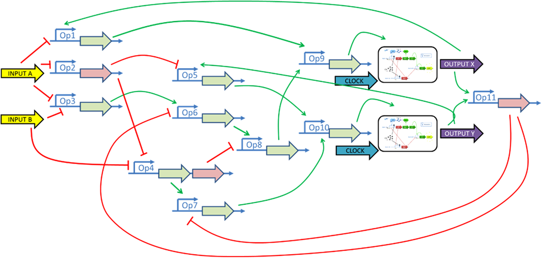
The GNR compiler and the associated GPL optimize the rough implementation of the Verilog description given by the digital synthesizer and find a way to produce the Boolean functions with parts picked up from the GPL. For this example, the GPL1 library is used. The 59 Boolean statements can be implemented with only 11 parts (1 NOR, 7 INH, 3 OR) picked up from the library. In addition, two biological D-flip-flops are implemented to map the two registers. The diagram of the equivalent gene regulatory network is given in Figure 6. The combinatorial part (excluding the D flip-flop) is composed with 11 BioParts and 14 genes. The cost of the combinatorial part system is 23.1 and its delay is 5. The output interface is then used to generate the System-C AMS model of the suggested GRN.
Synthesized GRN of the BiOFSM including eleven BioParts and two biological flip-flops.
Simulation of the GRN is achieved at two stages. First, the BLIF file generated by the GRN is simulated on an event-driven simulator (digital simulator), to validate the circuits at a Boolean level. Then, an ODE-based solver involved in the System-C AMS model is used in order to simulate the GRN in a given context. Results are given in Figure 7. The test scenario used for the simulation corresponds to three injections of X at 2500, 4200, and 7000 seconds, and two peaks of consumption at 5700 and 8000 seconds. For all parts, default biological parameters given in Table 2 are used.
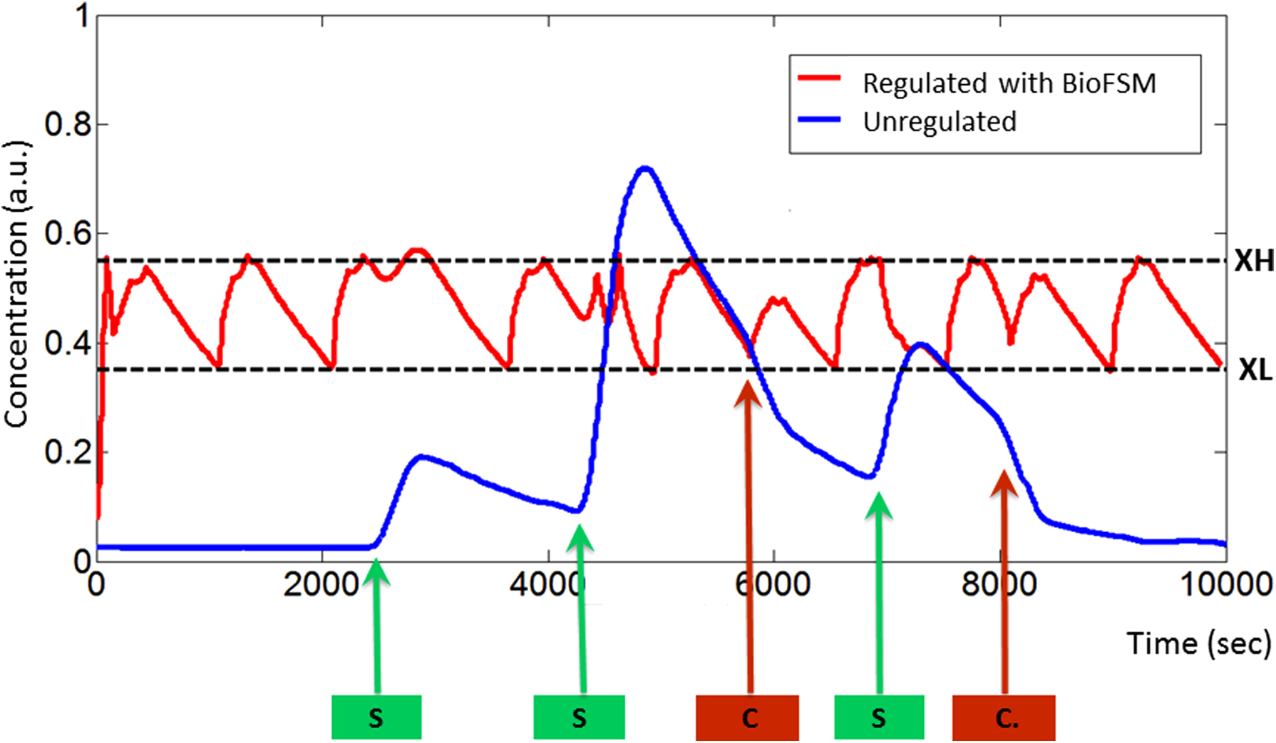
Simulation results obtained with the SystemC-AMS model. As stimuli, protein under regulation is synthesized at 2500 sec, 4200 sec, and 7000 sec, and is consumed at 5700 sec and 8000 sec.
5. Discussion and Conclusion
The framework described in this article shows the feasibility of the extension of CAD tools from electronics to synthetic biology, and more specifically in the context of the design of genetic regulatory networks based on a digital approach. It has been demonstrated on several digital circuits, including a small sequencer corresponding to a biological regulation system. The computation is almost instantaneous. It has also been tested on large-scale circuits (even if they are not yet achievable with current biological technology) as, for instance, a small 6-bits microprocessor composed with more than 500 BioParts. The computation time for the full workflow is less than 10 seconds on a standard computer.
This work is only the very first step toward the development of a complete GDA for GRNs. A high-level specification is turned into a GRN by giving the activation and repression links between genes and promoters. Nevertheless, this study is based on a number of assumptions that are questionable today within the scientific community (Lux et al., 2012). The most important is the ability to have biological parts that are decoupled from their environment [i.e., they do not significantly alter neither the natural behavior of the cell, nor the other implemented parts (as is the case in electronic when the conditions on the input and output impedances are met)].
The correspondence between the constructions suggested by GeNeDA and actual implementation of these functions is not straightforward. The design of Boolean gates in biology have already been achieved in several ways (Miyamoto et al., 2013), as for example, enzyme- and protein-based logic systems (Zhou et al., 2009), the use of standard genetic constructs (Guet et al., 2002), zinc-finger proteins (Laity et al., 2001), the use of transcription activator-like effectors (TALE) in mammalian cells (Lebar et al., 2014), multicellular constructs (Tamsir et al., 2011), micro RNA (Hemphill and Deiters, 2013; Rinaudo et al., 2007; Xie et al., 2011), riboswitches (Topp and Gallivan, 2010), deoxyribizyme (Stojanovic et al., 2002), immobilized DNA (Frezza et al., 2007). In this example, only standard constructs have been explored.
However, the software is generic enough to be suitable for alternative technology by adapting the GPL. Mapping Boolean abstracted functions and actual biological parts implies having, at first, a complete database of these parts with, for each of them, the digital function, the biological parameters (promotor strength, affinity of regulating proteins, transcription, and translation rate …) and assembly rules, as suggested by Canton and Endy (2008). Such a database might be built on an existing part repository such as JBEI (Ham et al., 2012) or the Virtual Part Repository (Cooling et a.l, 2010). Moreover, algorithms could be developed in order to turn directly the abstracted GRN suggested by GeNeDA into an actual GRN using parts from these repositories.
To perform this operation, one can take advantage of the extensible structure of SystemC-AMS. It is possible to actually build a dedicated algorithm that is able to run GeNeDA, gather the SystemC-AMS model, link abstracted parts to actual ones, replace default parameters with actual parameters in the model, simulate, and evaluate the solution. Moreover, it is possible to develop any design loop involving global and local optimizations and allowing for a higher modeling efficiency and faster simulations by several orders of magnitude. This point is still under investigation. Up to now, one way to perform this operation is to connect our tool to existing ones, such as GenoCAD or Tinkercell.
For over 40 years, the engineers and researchers in the field of microelectronic circuit design had developed a large number of software dedicated to the automation of circuit design. Considering that the ability to describe biological systems with HDL that can be understood by electronic tools has already been shown (Gendrault et al., 2014), we are sitting on a gold mine for the development of GDA tools without re-inventing the wheel. ABC and ODIN II are examples that pave the way to new avenues to build a complete digital synthesizer.
Footnotes
Acknowledgments
The authors would like to acknowledge Loic Bauer (engineer from Telecom Physique Strasbourg, France) for his valuable contribution on this work during his master thesis, and Aurélien Brooke (student at Telecom Physique Strasbourg) who was in charge of the design of the website. GeNeDA is available online: ![]()
Author Disclosure Statement
No competing financial interests exist.
References
Supplementary Material
Please find the following supplemental material available below.
For Open Access articles published under a Creative Commons License, all supplemental material carries the same license as the article it is associated with.
For non-Open Access articles published, all supplemental material carries a non-exclusive license, and permission requests for re-use of supplemental material or any part of supplemental material shall be sent directly to the copyright owner as specified in the copyright notice associated with the article.